

Page 1

Owner's Manual
ELECTRIC START
42" MOWER
6 SPEED TRANSAXLE
LAWN TRACTOR
Model No.
917.271532
• Safety
• Assembly
• Operation
• Maintenance
• Repair Parts
CAUTION:
Read and follow all Safety
Rules and Instructions before
operating this equipment.
Sears, Roebuck and Co., Hoffman Estates, II 60179
Visit our Craftsman website:www.sears.conYcraftsman
For answers to yourquestions
about this product,Call:
1-800-659-59t7
Sears Craftsman Help Line
5 am - 5prn, Mon - Sat
Page 2
Warranty...............................................2
SafetyRules.........................................3
ProductSpecifications..........................6
Assembly..............................................8
Operation............................................11
MaintenanceSchedule......................17
LIMITED TWO YEAR WARRANTY ON CRAFTSMAN RIDING EQUIPMENT PARTS
For two (2) years from the date of purchase, if this Craftsman Riding Equipment is
maintained, lubricated and tuned up according to the instructions in the owner's
manual, Sears will repair or replace, free of charge, any parts found to be defective in
material or workmanship. Warranty service is available free of charge by returning your
Craftsman riding equipmentto your nearest Sears Service Center. In-home warranty
service is available but a trip charge will apply. This warranty applies only while this
product is in the United States.
This Warranty does not cover:
• Expendable items which become worn during normal use, such as blades, spark
plugs, air cleaners, belts and oil tilters.
• Tire replacement or repair caused by punctures from outside objects, such as nails,
thorns, stumps, or glass.
• Repairs necessary because of operator abuse, including but not limited to, damage
caused by towing objects beyond the capability of the riding equipment, impacting
objects that bend the frame or crankshaft, or over speeding the engine.
• Repairs necessary because of operator negligence, including but not limited to,
electrical and mechanical damage caused by improper storage, failure to use the
proper grade and amount of engine oil, failure to keep the deck clear of flammable
debns, or the failure to maintain the equipment according to the instructions con-
tained in the owner's manual.
• Engine (fuel system) cleaning or repairs caused by fuel determined to be contami-
nated or oxidized (stale). in general, fuel should be used within thirty (30) days of its
purchase date.
• Riding equipment used for commercial or rental purposes. A product is "used for
commercial purpose" if is used for any purpose other than single family household
dwellings or in usage where profit is made.
Maintenance ....................................... 17
Service and Adjustments .................... 21
Storage ............................................... 27
Troubleshooting ................................. 28
Repair Parts ........................................ 32
Parts Ordedng ..................... Back Cover
LIMITED 90 DAY WARRANTY ON BATTERY
For ninety (90) days from date of purchase, if any battery included with this dding
equipment proves defective in material or workmanship and our testing determines the
battery will not hold a charge, Sears will replace the battery at no charge. Warranty
service is available free of charge by returning your Craftsman riding equipment to
your nearest Sears Service Center. In-home warranty service is available but a trip
charge will apply. This warranty applies only while this product is in the United States.
TO LOCATE THE NEAREST SEARS SERVICE CENTER ORTO SCHEDULE IN-HOME
WARRANTY SERVICE, SIMPLY CONTACT SEARS AT 1-800-4-MY-HOME
This Warranty gives you specific legal rights, and you may also have other rights which
may vary from state to state.
Sears, Roebuck and Co., D/817 WA, Hofiman Estates, IL 60179
Page 3
MPORTAN'r: This cuttingmachine is capable of amputating hands and feet and
throwingobjects. Failure to observe the following safety instructionscould resut in
seriousinjury or death.
I.GENERAL OPERATION
• Read, understand,and follow all
instructionsin the manual and on the
machinebeforestarting.
• Only allow responsibleadults,who are
familiar withthe instructians,to operate
the machine.
• Clear the area of objectssuchas rocks,
toys,wire, etc., whichcouldbe picked
upand thrownby the blade.
• Be sure the area is clear of otherpeople
beforemowing, Stop machineif anyone
entersthe area.
• Never carry passengers.
• Do not mow in reverse unlessabsolutely
necessary. Always lookdown and
behind before and while backing.
• Be aware ofthe mower discharge
directionand do not point it at anyone,
Do not operatethe mower without either
the entiregrass catcher or the guard in
place.
• Slow down beforeturning.
• Never leave a runningmachine
unattended. Always turn off blades, set
parkingbrake, stop engine, and remove
keys before dismounting.
• Turn off blades when not mowing.
• Stop engine before removing grass
catcheror uncloggingchute.
• Mow only in daylight or good artificial
light.
• Do not operate the machine while under
the influenceof alcoholor drugs.
• Watch for trafficwhen operatingnear or
crossingroadways.
• Use extra care when loadingor unload-
ingthe machine intoa traileror truck.
• Data indicatesthatoperators, age 60
years and above, are involvedin a large
percentageof riding mower-related
injuries.These operators should
evaluate their abilityto operate the riding
mowersafely enoughto protect them-
selves and othersfrom serious injury.
• Keep machinefree of grass, leaves or
other debrisbuild-upwhich can touch
hotexhaust/ engine parts and burn. Do
not allow the mower deck to plow leaves
or other debris whichcan cause build-
upto occur.Clean anyoil orfuel
spillagebefore operatingor storingthe
machine. Allow machine to coolbefore
storage.
II. SLOPE OPERATION
Slopesare a majorfactor related to loss-of-
controland tipoveraccidents,whichcan re-
suit in severe injury or death. All slopes
require extra caution. Ifyou cannotback up
the slope or if you feel uneasy on it, do not
mow it.
DO:
• Mow up and down slopes, not across.
• Remove obstacles such as rocks,tree
limbs, etc.
Watch for holes, ruts, or bumps. Uneven
terrain couldovedum the machine. Tall
grass can hide obstacles.
Use slow speed. Choose a lowgear so
that you will not have to stop or shift
while on the slope.
Follow the manufacturer's recommenda-
tions for wheel weights or counter-
weights to improvestability.
Use extra care withgrass catchers or
other attachments. These can change
the stabiJityof the machine.
Keep all movement on the slopes slow
and gradual. Do not make sudden
changes in speed or direction.
Avoid starting or stopping on a slope, if
tires bosetraction, disengage the blades
and proceed slowly straight down the
slope.
DO NOT:
• Do not turn on slopes unless necessary,
and then, tam slowly and gradually
downhill, if possible.
• Do not mow near drep-offs, dftches, or
embankments. The mower could
suddenly tam over if a wheel is over the
edge of a cliff or ditch, or if an edge
caves in.
• Do not mow on wet grass. Reduced
traction couldcause sliding.
• Do not try to stabilize the machine by
putting your foot on the ground.
• Do notuse grasscatcher on steep
slopes.
3
Page 4
Ill. CHILDREN
Tragic accidentscan occurif the operator
is not alert to the presence of children.
Children are often attracted to the
machine and the mowing activity. Never
assume that children will remain where
you last saw them.
• Keep children out of the mowing area
and under the watchful care of another
responsible adult.
• Be alert and turn machine off if children
enter the area.
• Before and when backing, look behind
and down for small children.
• Never carry children. They may fall off
and be seriously injured or interfere
with safe machine operation.
• Never allow children to operate the
machine.
• Use extra care when approaching blind
corners, shrubs, trees, or other objects
that may obscurevision.
IV. SERVICE
• Use extra care in handling gasoline
and other fuels. They are flammable
and vapors are explosive.
-Use only an approved container.
-Never remove gas cap or add fuel
with the engine running. Allow
engine to cool before refueling. Do
not smoke.
-Never refuel the machine indoors.
-Never store the machine or fuel
container inside where there is an
open flame, such as a water heater.
• Never run a machine inside a closed
a.rea.
• Keep nuts and bolts, especially blade
attachment bolts, tight and keep
equipment in good condition.
• Never tamperwith safety devices.
Check their proper operation regularly.
• Keep machine free of grass, leaves, or
other debris build-up. Clean oil or fuel
spillage. Allow machineto cool before
storing.
• Stop and inspectthe equipment ifyou
strike an object. Repair, if necessary,
before restarting.
• Never make adjustments or repairs
with the engine running.
• Grass catcher components are subject
to wear, damage, and deterioration,
which could expose moving parts or
allow objects to be thrown. Frequently
check components and replace with
manufacturer's recommended parts,
when necessary.
• Mower blades are sharp and can cut.
Wrap the blade(s) or wear gloves, and
use extra caution when servicing them.
• Check brake operation frequently.
Adjust and service as required.
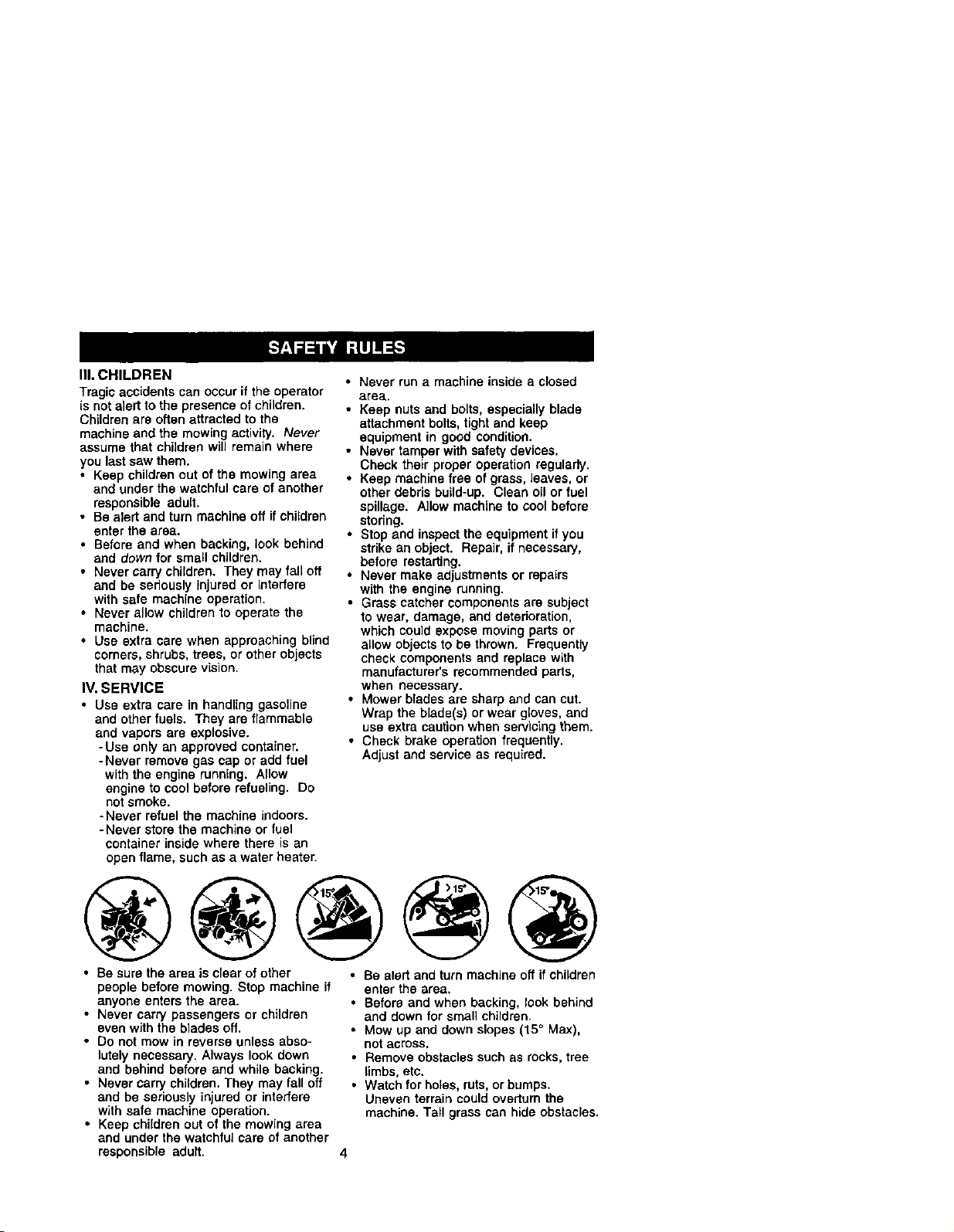
@@@@@
• Be sure the area is clear of other
people before mowing. Stop machine if
anyone enters the area.
• Never carry passengers or children
even with the blades off.
• Do not mow inreverse unless abso-
lutely necessary. Always look down
and behind before and while backing.
• Never carry children. They may fall off
and be seriously injured or interfere
with safe machine operation.
• Keep children out of the mowing area
and under the watchful care of another
responsible adult.
• Be alert and turn machine off if children
enter the area.
• Before and when backing, look behind
and down for small children.
• Mow up and down slopes (15° Max),
not across.
• Remove obstacles such as rocks, tree
limbs,etc.
• Watch for holes,ruts, or bumps.
Uneven terrain could overturn the
machine. Tall grass can hide obstacles.
Page 5
• Useslowspeed.Choosealowgearso
thatyouwill nothave to stop or shift
while on the slope.
• Avoid starting or stopping on a slope. If
tires lose traction, disengage the
blades and proceed slowly straight
down the slope.
• If machine stops while going uphill,
disengage blades, shift into reverse
and back down slowly.
• Do not turn on slopes unless neces-
sary, and then, turn slowly and gradu-
ally downhill, if possible.
_{_Look for this symbol to point out
important safety precautions. It means
CAUTIONIE[ BECOMEALERTI!! YOUR
SAFETY ISINVOLVED.
_,CAUTION: In order to prevent acci-
dental starting when setting up, transport-
ing, adjusting or making repairs, always
disconnect spark plug wire and place
wire where it cannot contact spark plug.
_,CAUTION: Do not coast down a hill in
neutral, you may lose control of the
tractor.
_CAUTION: Tow onlythe attachments
that are recommendedby and comply
with specifications of the manufacturer of
your tractor. Use common sense when
towing. Operate only at the lowest
possible speed when on a slope. Too
heavy of a load, while on a slope, is
dangerous. ]ires can lose traction with
the ground and cause you to lose control
of your tractor.
_WARNING: Engineexhaus some of
its constituents, and certain ve'hicle
components contain or emit chemicals
known to the State of California to cause
cancer and birth defecLs or other repro-
ductive harm.
_I,WARNING: Battery posts terminals
and related accessones conta nead and
lead compounds, chemicals known to the
State of California to cause cancer and
birth defects or other reproductive harm.
Wash hands after handling,
5
Page 6
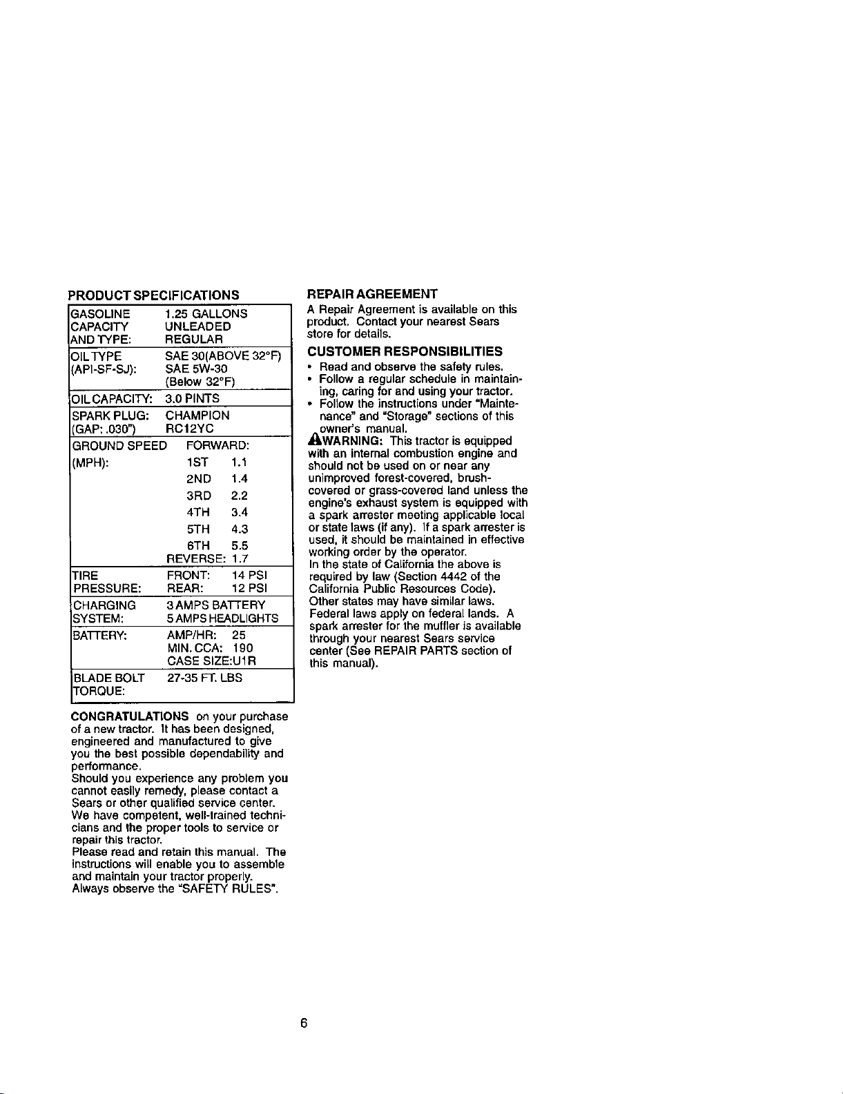
PRODUCT SPECIFICATIONS
GASOUN r= 1.25 GALLONS
CAPACITY UNLEADED
_ND TYPE: REGULAR
OILTYPE SAE 30(ABOVE 32°F)
_,PI-SF-SJ): SAE 5W-30
(Below 32°F)
OIL CAPACITY: 3.0 PINTS
SPARK PLUG: CHAMPION
GAP: .030") RCt2YC
GROUND SPEED FORWARD:
(MPH): 1ST 1.1
2ND 1.4
3RD 2.2
4TH 3.4
5TH 4.3
6TH 5.5
REVERSE: 1.7
TIRE FRONT: 14 PSI
PRESSURE: REAR: 12 PSI
CHARGING 3 AMPS BATTERY
SYSTEM: 5 AMPSHEADLIGHTS
BATTERY: AMP/HR: 25
MIN. CCA: 190
CASE SIZE:U1R
3LADE BOLT 27-35 FT. LBS
FORQUE:
REPAIR AGREEMENT
A Repair Agreement is available on this
product. Contactyour nearest Sears
store for details.
CUSTOMER RESPONSIBILITIES
• Read and observe the safety rules.
• Follow a regular schedule in maintain-
ing, caring for and using your tractor.
• Follow the instructions under "Mainte-
nance" and "Storage" sections of this
owner's manual.
_WARNING: This tractor is equipped
with an internal combustion engine and
should not be used on or near any
unimproved forest-covered, brush-
covered or grass-covered land unless the
engine's exhaust system is equipped with
a spark arrester meeting applicable local
or state laws (if any). if a spark arrester is
used, it should be maintained in effective
working order by the operator.
In the state of California the above is
required by law (Section 4442 of the
California Public Resources Code).
Other states may have similar laws.
Federal laws apply on federal lands. A
spark arrester for the muffler is available
through your nearest Sears service
center (See REPAIR PARTS section of
this manual).
CONGRATULATIONS on your purchase
of a new tractor. It has been designed,
engineered and manufactured to give
you the best possible dependability and
performance.
Should you experience any problem you
cannot easily remedy, please contact a
Sears or other qualifiedservice center.
We have competent, well-trainod techni-
cians and the proper tools to service or
repair thistractor.
Please read and retain this manual. The
instructionswill enable you to assemble
and maintainyour tractor properly.
Alwaysobserve the =SAFETY RULES".
6
Page 7
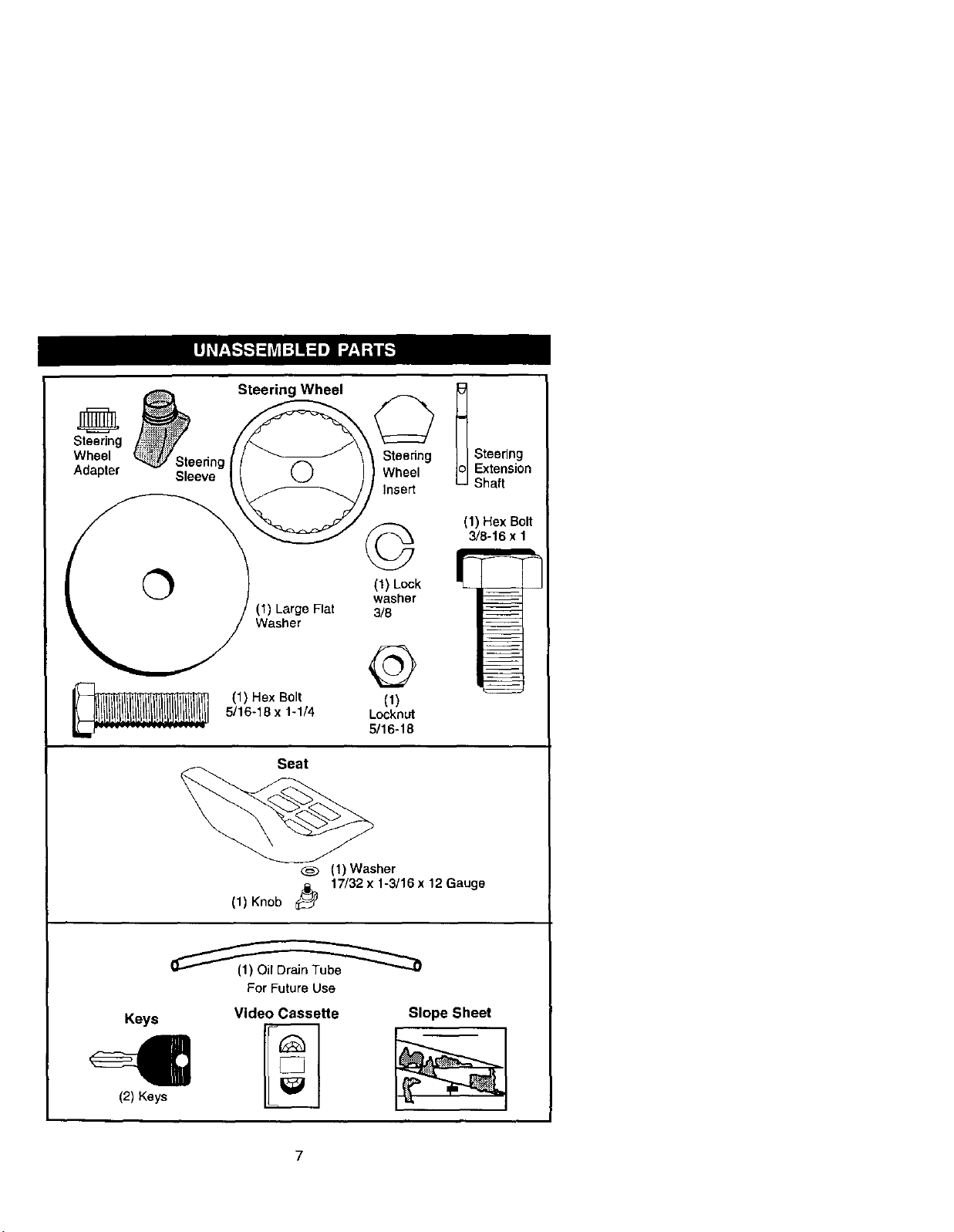
Steering Wheel
Steering
Wheel
Adapter
Steering
Wheel
Insert
3/8
@
5/16-18 x 1-1/4 Locknut
(1) Hex Bolt (1)
Seat
Knob
11)
5/16-18
(1) Washer
17/32 x 1-3/16 x 12 Gauge
t Steedng
Extension
Shaft
(1) Hex Bolt
3/8-16 x 1
Keys
(2) Keys
For Future Use
Video Cassette
7
Slope Sheet
Page 8
Your new tractor has been assembled at the factory with exception of those parts left
unassembled for shipping purposes. To ensure safe and proper operation of your
tractor all parts and hardware you assemble must be tightened securely. Use the
correct tools as necessary to insure proper tightness. Review the video cassette before
you begin.
TOOLS REQUIRED FOR
ASSEMBLY
A socket wrench set will make assembly
easier. Standard wrench sizes you need
are listed below.
(1) 9/16"wrench (1) Pliers
(1) 1/2"wrench (1) Utilityknife
(1) 33rapressure gauge
When right or left hand is mentioned in
this manuel, it means, from your point of
view, when you are in the operating
position (seated behind the steering
wheel).
TO REMOVE TRACTOR FROM
CARTON
UNPACK CARTON
1. Remove all accessible loose parts
and parts cartons from carton.
2. Cut, from top to bottom, along lines
on all four comers of carton, and lay
panels flat.
3. Check for any additional loose parts
or cartons and remove.
BEFORE REMOVING TRACTOR
FROM SKID
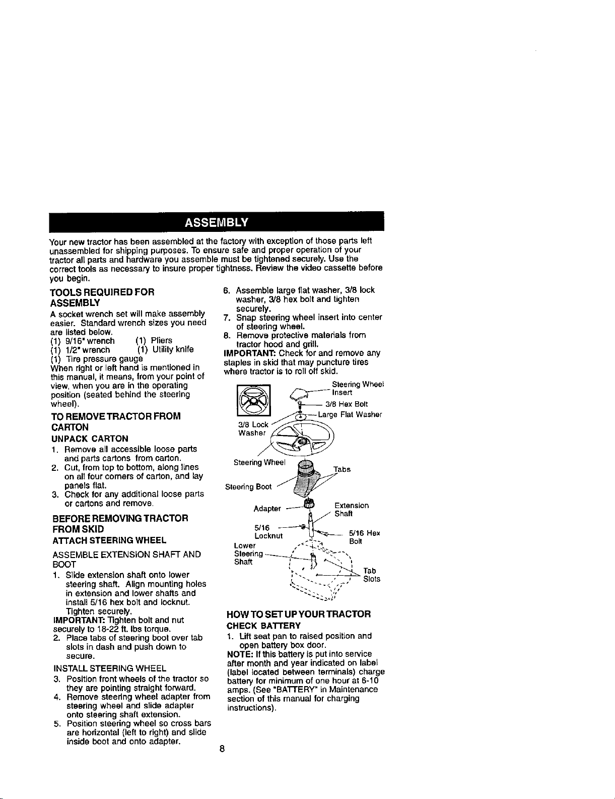
ATTACH STEERING WHEEL
ASSEMBLE EXTENSION SHAFT AND
BOOT
1. Slide extension shaft onto lower
steering shaft. Align mounting holes
in extension and lower shafts and
install 5/16 hex bolt and Iocknut.
Tighten securely.
IMPORTANT: Tighten bolt and nut
securely to 18-22 ft. Ibs torque.
2. Place tabs of steering boot over tab
slots in dash and push down to
secure.
INSTALL STEERING WHEEL
3. Position front wheels of the tractorso
they are pointing straight forward.
4. Remove steering wheel adapter from
steering wheel and slide adapter
onto steering shaft extension.
5. Position steedng wheel so cross bars
are horizontal (left to right) and slide
inside boot and onto adapter.
6. Assemble large flat washer, 3/8 lock
washer, 3/8 hex bolt and tighten
securely.
7. Snap steering wheel insert into center
of steering wheel.
8. Remove protective materials from
tractor hood and grill.
IMPORTANT:. Check for and remove any
staples in skid that may puncture tires
where tractor is to roll off skid.
SteeringWheel
_ Inse_
_ La_8 H,eaxt_i_;sher
3/8 Lockf_
Wash_
Steering Whee_ab s
SteeringBoot f _"
Adapter_ Extension
v , _j Shaft
I
D'kou to"o"
Lower ," "'_-L.-.
Steering_ ,_ "'::" "-
sha. _ ", ",,
' "" _ Slots
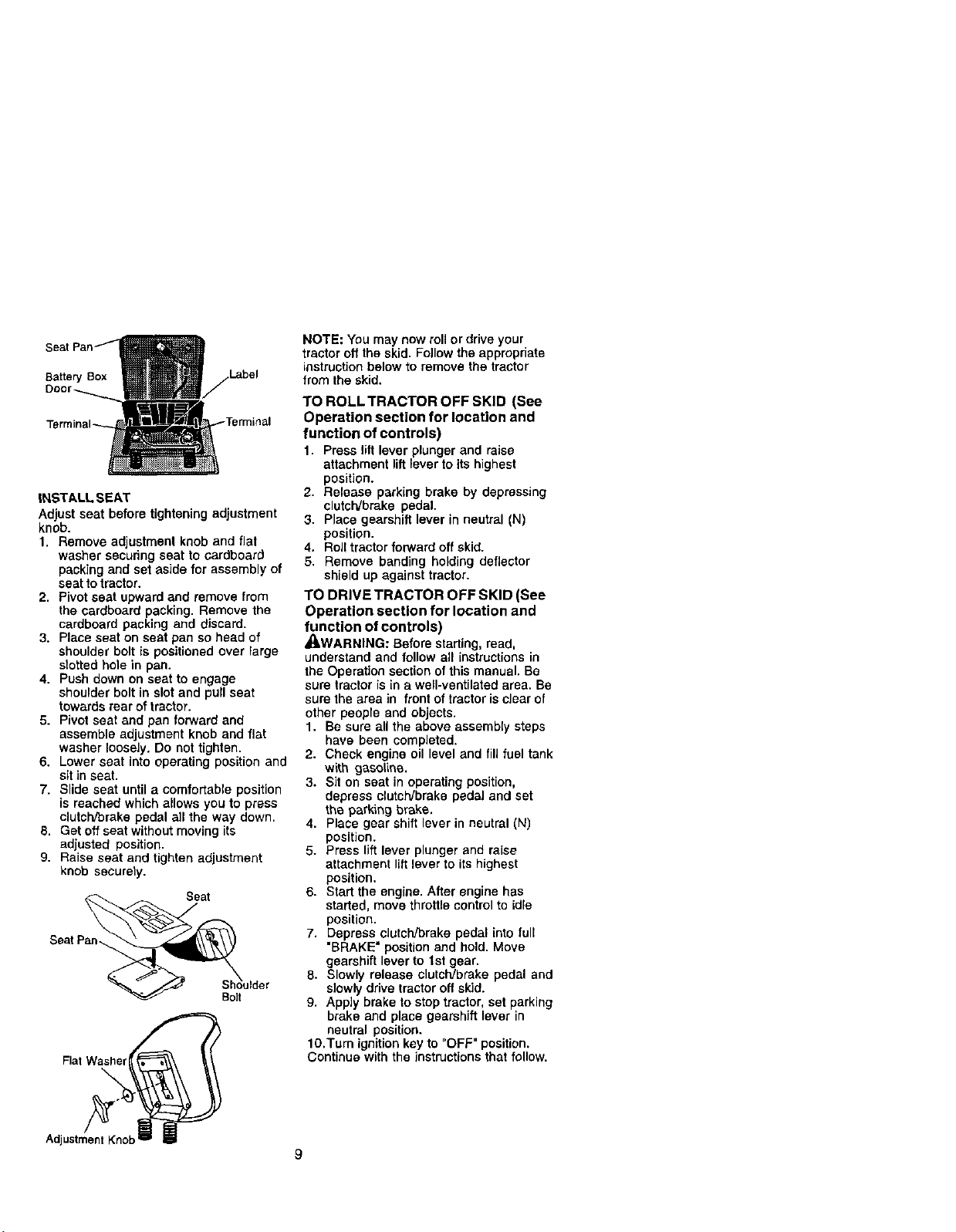
HOW TO SET UP YOUR TRACTOR
CHECK BATTERY
t. Lift seat pan to raised positionand
open battery box door.
NOTE: Ifthis battery is put into service
after month and year indicated on label
(label located between terminals) charge
battery for minimum of one hour at 6-10
amps. (See =BA'rrERY" in Maintenance
section of this manual for charging
instructions).
8
Page 9
_rminal
INSTALL SEAT
Adjust seat before tighteningadjustment
knob.
1. Remove adjustment knob and flat
washer securing seat to cardboard
packingand set aside for assembly of
seat to tractor,
2. Pivotseat upwardand remove from
the cardboard packing, Remove the
cardboard packing and discard.
3. Place seat on seat pan sohead of
shoulderbolt is positioned over large
stotted hole in pan.
4. Push down on seat to engage
shoulderbolt in slot and pull seat
towardsrear of tractor.
5. Pivot seat and pan forward and
assemble adjustment knob and flat
washer loosely. Do nottighten.
6, Lower seat into operating positionand
sit in seat.
7. Slide seat until a comfortable position
is reached which allows you to press
clutch/brake pedal all the way down.
8. Get off seat without moving its
adjusted position.
9. Raise seat and tighten adjustment
knob securely.
Seat
Bo]t
FiatWasher
NOTE: You may now roll or drive your
tractor off the skid. Follow the appropriate
instruction below to remove the tractor
from the skid.
TO ROLL TRACTOR OFF SKID (See
Operation section for location and
function of controls)
1. Press lift lever plunger and raise
attachment lift lever to its highest
position.
2. Release parking brake by depressing
clutclVbrake pedal.
3. Place gearshift lever in neutral (N)
position.
4. Roll tractor forward off skid.
5. Remove banding holding deflector
shield up against tractor.
TO DRIVE TRACTOR OFF SKID (See
Operation section for location and
function of controls)
_I,WARNING: Before starting, read,
understand and follow all instructions in
the Operation section of this manual. Be
sure tractor is in a well-ventilated area. Be
sure the area in front of tractor is clear of
other people and objects.
1. Be sure all the above assembly steps
have been completed.
2. Check engine oillevel and fill fuel tank
with gasolina.
3. Sit on seat in operating position,
depress clutch/brake pedal and set
the parking brake.
4. Place gear shift lever in neutral (N)
position.
5. Press lift lever plunger and raise
attachment lift lever to its highest
position.
6. Start the engine. After engine has
started, move throttle control to idle
position.
7. Depress clutch/brake pedal into lull
"BRAKE" position and hold. Move
gearshift lever to tst gear.
8. Slowly release clutch/brake pedal and
s]owly drive tractoroff skid.
9. Apply brake to stop tractor, set parking
brake and place gearshift lever in
neutral position.
lO.Tum ignition key to "OFF" position.
Continue with the instructions that follow.
AdjustmentKnob=p B
Page 10

CHECK TIRE PRESSURE
The tiros on your tractor were ovednflated
at the fadory for shipping purposes.
Correct tire pressure is important for best
cutting performance.
• Reduce tire pressure to PSI shown in
"PRODUCT SPECIFICATIONS" section
of this manual.
CHECK DECK LEVELNESS
For best cuttingresults, mower housing
should be propedy leveled. See "TO
LEVEL MOWER HOUSING" in the
Service and Adjustments section of this
manual.
CHECK FOR PROPER POSITION OF
ALL BELTS
See the figures that are shown for
rep_ecieg motion and mower blade drive
belts in the Service and Adjustments
section of this manual. Verify that the
belts are routedcorrectly.
CHECK BRAKE SYSTEM
After you learn how to operate your
tractor,check to see that the brake is
properly adjusted. See "TO ADJUST
BRAKE" in the Service and Adjustments
section of this manual.
V"CHECKLIST
Before you operate and enjoy your new
tractor,we wish to assure that you receive
the best performance and satisfaction
fromthis Quality Product,
Please review the followingchecklist:
,,'All assembly instructions have been
completed.
./No remaining loose parts in carton.
./Battery is properlyprepared and
charged. (Minimum 1 hour at 6 amps).
./Seat is adjusted comfortablyand
tightened securely.
.//'Alltires are properlyinflated. (For
shipping purposes, the tires were
overlnfiatedat the factory).
./Be sure mower deck is properly leveled
side-to-side/front-to-rearfor best cutting
results. (Tires must be properly inflated
for leveling).
./Check mower and drive belts. Be sure
they are routed properly around pulleys
and inside all belt keepers.
./Check wiring. See that all connections
are still secure and wires are properly
clamped.
While learning how to use your tractor,
pay extra attention to the following
important items:
./Engine oil is at proper level.
./'Fuel tank is filled with fresh, clean,
regular unleaded gasoline.
./Become familiar with all controls - their
location and function. Operate them
before you start the engine.
./Be sure brake system is in safe
operating condition.
10
Page 11
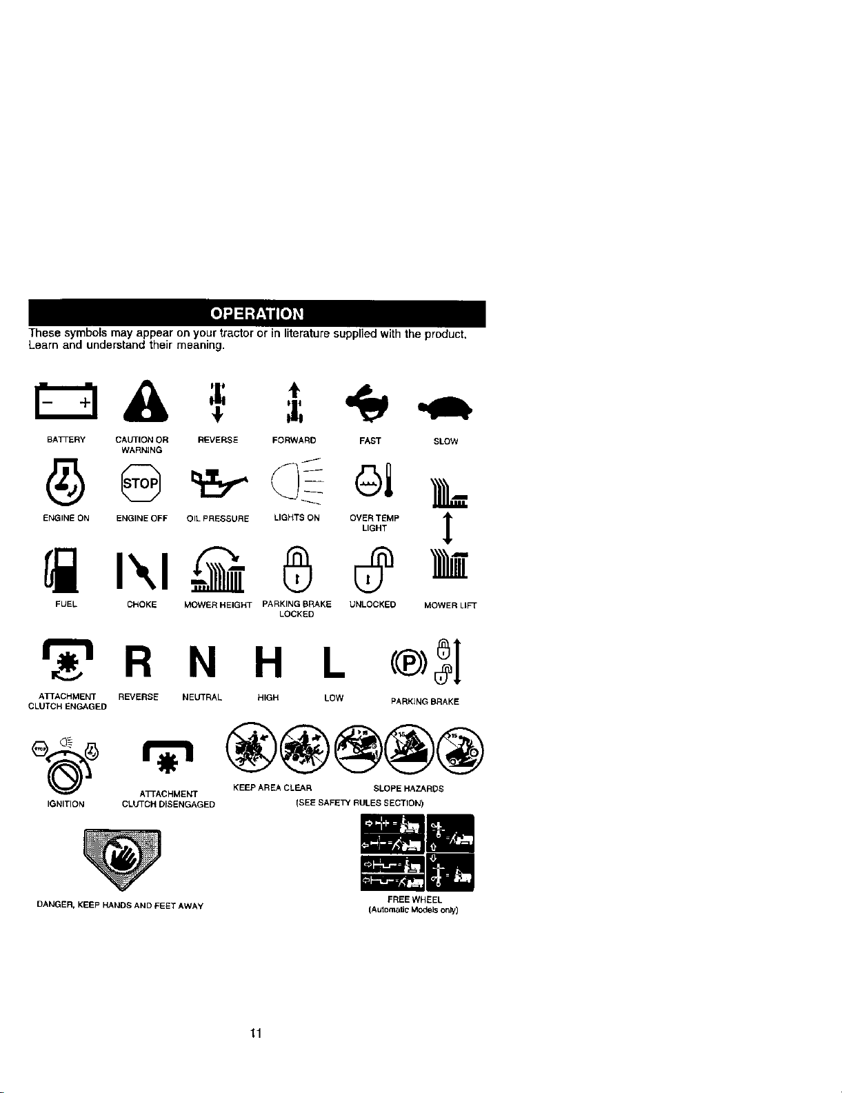
These symbolsmay appear on your tractor or in literaturesupplied with the product.
Learn and understand their meaning.
BA3-i-E Ry CAUTION OR REVERSE FORWARD FAST SLOW
WARN]NG
ENG,.SO.e.G,NSOSFO,LPRSSSORSL,O.TEONO%_.IMPT
FUEL CNOKE MOWER HEIGHT PARKING BRAKE UNLOCKED
_r_R N H L
ATTACHMENT REVERSE NELrTRAL HIGH LOW
CLUTCH ENGAGED
LOCKED
®3]
PARKING BRAKE
®@@@@
KEEP AREA CLEAR SLOPE HAZARDS
(SEE SAFETY RULES SECTION)
IGNITION
A_ACHMENT
CLUTCH DISENGAGED
4,
MOWER LIFT
DANGER, KEEP HANDS AND FEET AWAY
11
FREE WHEEL
(Automatic Models onty)
Page 12
KNOWYOUR TRACTOR
READ THIS OWNER'S MANUAL AND SAFETY RULES BEFORE OPERATING
YOUR TRACTOR
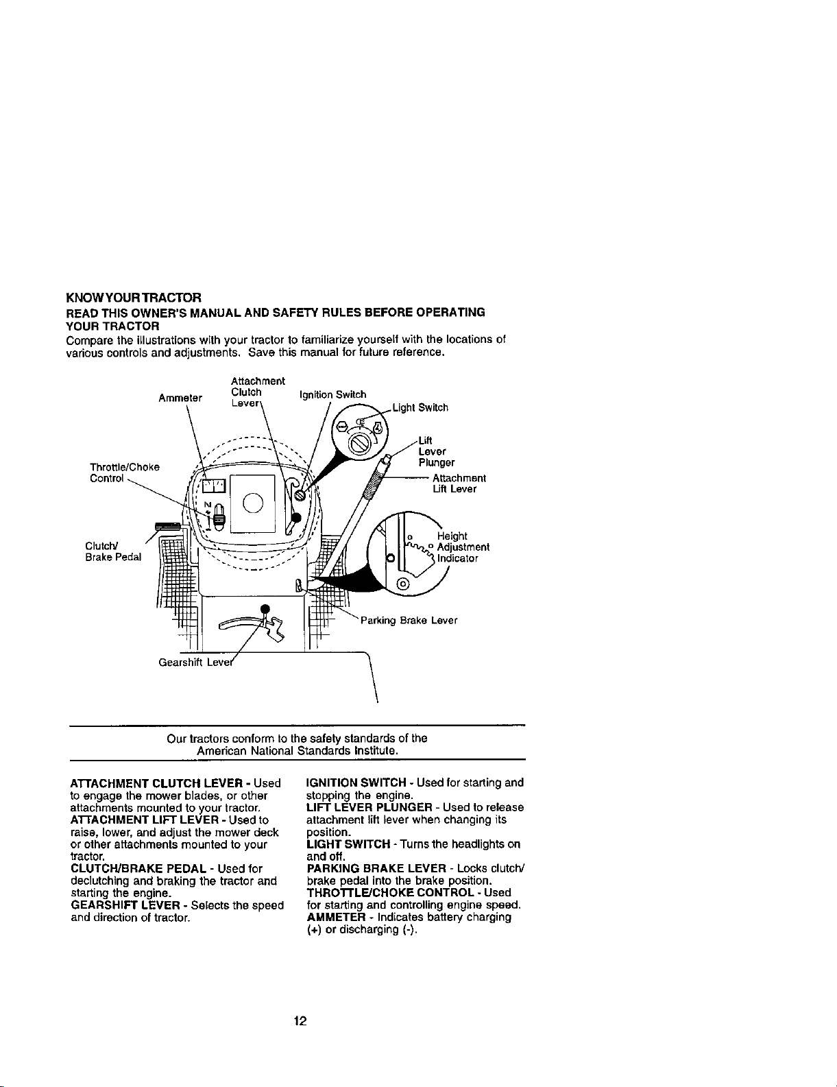
Compare the igustrationswith your tractor to familiarize yourself with the locations of
various controls and adjustments. Save this manual for future reference.
Attachment
Ammeter Clutch Ignition Switch
Throttle/Choke
Control
Switch
Lever
Plunger
LiftLever
Clutch/ _Adjustment
Brake Pedal Indicator
_Brake Lever
Gearshift
Height
\
Our tractorsconformto the safety standardsof the
Amedcan National Standards Institute.
ATrACHMENT CLUTCH LEVER - Used
to engage the mower blades, or other
attachmentsmounted toyour tractor,
ATI'ACHMENT LIFT LEVER - Used to
raise, lower, and adjust the mower deck
or other attachments mounted to your
tractor.
CLUTCH/BRAKE PEDAL - Used for
declutchingand braking the tractor and
starting the engine.
GEARSHIFT LEVER - Selects the speed
and directionof tractor.
IGNITION SWITCH - Usedfor starting and
stoppingthe engine.
LIFT LEVER PLUNGER - Used torelease
attachment lilt leverwhen changing its
position.
LIGHT SWITCH - Turns the headlightson
and off.
PARKING BRAKE LEVER - Locks clutch/
brake pedal into the brake position.
THRO'rFLE/CHOKE CONTROL - Used
for startingand controllingengine speed,
AMMETER - Indicatesbattery charging
(+) or discharging (-).
12
Page 13

The operation of any tractor can result in foreign objects thrown into the
eyes which can result in severe eye damage. Always wear safety
glasses or eye shields while operating your tractor or performing any
_adjustments or repairs. We recommend a wide vision safety mask over
spectaoles or standard safety glasses.
HOW TO USE YOUR TRACTOR
TO SET PARKING BRAKE
Your tractor is equipped with an operator
presence sensing switch. When engine
is running,any attempt by the operator to
leave the seat without firstsetting the
parkingbrake will shut off the engine.
1. Depress clutch/brake pedal into full
"BRAKE" position and hold.
2. Place parkingbrake lever in "EN-
GAGED" position and release
pressure from clutch/brake pedal.
Pedal should remain in "DRAKE"
position. Make sure parking brake will
hold tractor secure.
Attachment Clutch Lever
Throttle/Choke
F'osition
ignitionKey
/
Clutch
Broke
pedal
Brake
"Engaged"
Position
Gearshift
=Brake"
Position "Disengage 6_"
STOPPING
Position
MOWER BLADES -
• TO stop mower blades,move attach-
ment clutch lever to =DISENGAGED"
position.
GROUND DRIVE -
• To stop ground drive, depress clutch/
brake pedal into full "BRAKE" position.
• Move gearshift lever to neutral (N)
position.
ENGINE -
• Move throttle control to slow position.
NOTE: Failure to move throttlecontrol to
slow position and allowing engine to idle
before stopping may cause engine to
=backfire".
Lever
• Turn ignition key to "OFF" position and
remove key. Always remove key when
leaving tractor to prevent unauthorized
use.
• Never use choke to stop engine.
IMPORTANT: Leaving the ignition switch
in any positionother than "OFF" will
cause the battery to be discharged,
(dead).
NOTE: Under certain conditions when
tractor is standing idle with the engine
running, hot engine exhaust gases may
cause "browning" of grass. To eliminate
this possibility, always stop engine when
stopping tractor on grass areas.
_kCAUTION: Always stop tractor
completely,as described above, before
leavingthe operator's position;to empty
grass catcher,etc.
TO USE THROTTLE CONTROL
Always operate engine at full throttle.
• Operating engine at less than full
throttlereduces the battery charging
rate.
• Full throttle offers the best bagging and
mower performance.
TO MOVE FORWARD AND BACK-
WARD
The directionand speed of movement is
controlledby the gearshift lever.
1. Start tractor with clutch/brakepedal
depressed and gearshift lever in
neutral (N) position.
2. Move gearshift lever to desired
position.
3. Slowly release cJutch/brakepedal to
start movement.
IMPORTANT: Bring tractorto a complete
stop before shiftingor changing gears,
Failure todo so will shorten the useful life
of your transaxle.
TO ADJUST MOWER CU'I-rlNG HEIGHT
The positionof the attachment lift lever
determines the cutting height.
• Grasp liftlever.
• Press plunger with thumb and move
lever to desired position,
13
Page 14
The cutting height range is approxi-
mately 1-1/2 to 4". The heights are
measured from the ground to the blade
tip with the engine not running. These
heights are approximate and may vary
depending upon soil conditions, height of
grass and types of grass being mowed.
• The average lawn shoaid be cut to
approximately 2-1/2 inches during the
cool season and to over 3 inches
during hot months. For healthier and
better looking lawns, mow often and
after moderate growth.
• For best cuttingperformance, grass
over 6 inches in height should be
mowedtwice. Make the first cut
relativelyhigh; the second to desired
height.
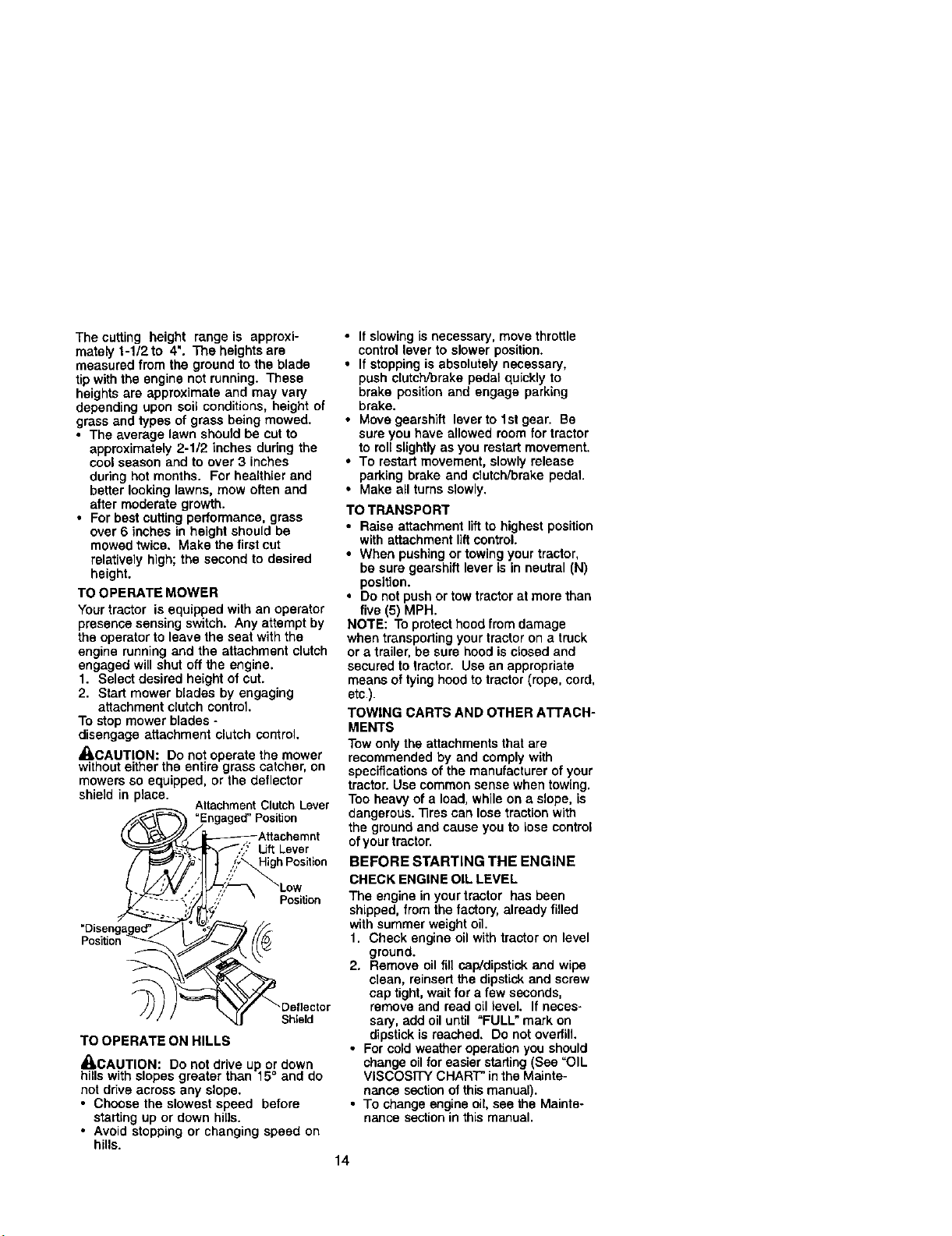
TO OPERATE MOWER
Your tractor is equipped with an operator
presence sensing switch. Any attempt by
the operator to leave the seat with the
engine running and the attachment clutch
engaged will shut off the engine.
1. Select desired height of cut.
2. Start mower blades by engaging
attachmentclutch control.
To stop mower blades -
disengage attachment clutch control.
_CAUTION: Do not operate the mower
withouteither the entire grass catcher, on
mowers so equipped, or the deflector
shield in place.
AttachmentClutchLever
Lift Lever
High Position
Position
Position _
Shield
TO OPERATE ON HILLS
_CAUTION: Do notdrive up or down
hills with slopes greater than 15° and do
not ddve across any slope.
• Choose the slowest speed before
starting up or down hills.
• Avoid stopping or changing speed on
hills.
• If slowingis necessary, move throttle
controllever to slower position.
• If stoppingis absolutelynecessary,
push clutchYorakepedal quickly to
brake position and engage parking
brake.
• Move gearshift lever to 1stgear. Be
sure you have allowed room for tractor
to rotislightlyas you restartmovement.
• To restart movement, slowlyrelease
parking brake and clutchForekepedal
• Make all turnsslowly.
TO TRANSPORT
• Raise attachment liftto highestposition
with attachment liftcontrol.
• When pushing or towingyour tractor,
be sure gearshiftlever is in neutral (N)
position.
• Do notpush or towtractor at more than
five(5) MPH.
NOTE: To protecthood fromdamage
when transporting your tractor on a truck
or a trailer, be sure hood is closed and
secured totractor. Use an appropriate
means of tying hood to tractor (rope, cord,
etc).
TOWING CARTS AND OTHER ATTACH-
MENTS
Tow only the attachmentsthat are
recommended by and comply with
specificationsof the manufacturerof your
tractor.Use common sense whentowing.
Too heavy of a load, while ona slope, is
dangerous. "13rescan lose tractionwith
the ground and cause you to lose control
of your tractor.
BEFORE STARTING THE ENGINE
CHECK ENGINE OIL LEVEL
The engine in your tractor has been
shipped,from the factory, already filled
with summer weight oil.
1. Check engine oil with tractor on level
ground.
2. Remove oil fill cap/dipstickand wipe
clean, reinsert the dipstick and screw
cap tight, wait for a few seconds,
remove and read oil level. If neces-
sary, add oil until "FULL" mark on
dipstickis reached. Do not overfill.
• For cold weather operation you should
change oil for easier starling(See "OIL
VISCOSITY CHART" in the Mainte-
nanca section of this manual).
• To change engine oil, see the Mainte-
nance sectionin thismanual.
14
Page 15
ADD GASOLINE
• Fill fuel tank. Use fresh, clean, regular
unleaded gasolinewith a minimumof
87 octane. (Use of leaded gasoline
will increase carbon and lead oxide
deposits and reduce valve life). Do not
mix oil withgasoline. Purchase fuel in
quantities that can be used within30
days to assure fuel freshness.
IMPORTANT: When operatingin
temperatures below 32°F(0°C), use fresh,
clean winter grade gasoline to help
insure good cold weather starting.
WARNING: Experience indicatesthat
alcohol blended fuels (called gasohol or
using ethanol or methanol)can attract
moisturawhich leads to separation and
formation of acids during storage. Acidic
gas can damage the fuel system of an
engine while in storage. To avoid engine
problems, the fuel system should be
emptied before storage of 30 days or
longer. Drain the gas tank, start the
engine and let it run until the fuel lines
and carburetor are empty. Use fresh fuel
nextseason. See Storage Instructions for
additional information. Never use engine
or carburetor cleaner products in the fuel
tank or permanent damage may occur.
_1_CAUTION: Fill to bottom of gas tank
filler neck. Do not ovediU. Wipe off any
spilled oil or fuel. Do not store, spill or
use gasoline near an open flame.
TO START ENGINE
When starting the engine for the first time
or if the engine has run out of fuel, it will
take extra cranking time to move fuel from
the tank to the engine.
1. Sit on seat in operating position,
depress clutch/Drake pedal and set
parking brake.
2. Place gear shift lever in neutral (N)
position.
3. Move attachment clutch to "DISEN-
GAGED" position.
4. Move throttle control to choke position.
NOTE; Before starting, read the warm
and cold starting procedures below.
5. Insert key into ignitionand turn key
clockwiseto "START" position and
release key as soon as engine starts.
Do not run starter continuously for
more than fifteen seconds per minute.
If the engine does not start after
several attempts, move throttle control
to fast position, wait a few minutes and
try again. If engine still does not start,
move the throttle control back to the
choke position and retry.
WARM WEATHER STARTING (50" F and
above)
6. When engine starts, move the throttle
controltothe fast position.
• The attachments and ground ddve can
now be used. if the engine does not
accept the load, restart the engine and
allow itto warm up for one minute
usingthe choke as described above.
COLD WEATHER STARTING ( 50° F and
below)
6. When engine starts, allow engine to
runwith the throttlecontrolin the
choke position until the engine runs
roughly,then move throttlecontrol to
fast position. This may require an
engine warm-up period from several
seconds to several minutes, depend-
ing on the temperature.
• The attachments can also be used
during the engine warm-up period.
NOTE: If at a high altitude (above 3000
feet) or in cold temperatures (below 32 F)
the carburetor fuel mixture may need to
be adjusted for best engine performance.
See "TO ADJUST CARBURETOR" in the
Service and Adjustments section of this
manual.
15
Page 16
MOWING TIPS
• Mower should be propedy leveled for
best mowingperformance. See "TO
LEVEL MOWER HOUSING" in the
Service and Adjustments section of this
manual.
• The left hand side of mower should be
used for trimming.
• Drive so that clippings are discharged
onto the area that has been cut. Have
the cutarea to the rightofthe tractor.
This will resultin a more even distribu-
tion of clippingsand more uniform
cutting.
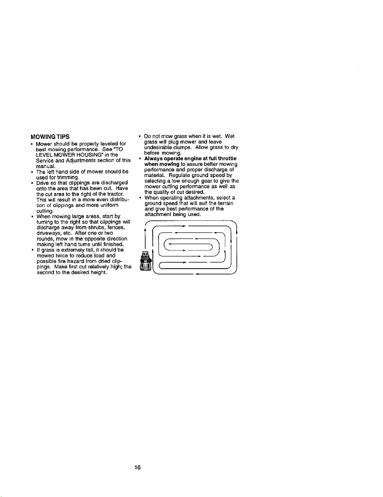
• When mowing large areas, start by
turningto the rightso that clippingswill
dischargeaway from shrubs, fences,
driveways, etc. After one or two
rounds,mow in the oppositedirection
making [eft hand turns until finished.
• If grass isextremely tall, itshouldbe
mowedtwice to reduce load and
possiblefire hazard from dried clip-
pings. Make first cut relativelyhigh;the
secondto the desired height.
• Do not mow grass when it is wet. Wet
grass will plug mower and leave
undesirable clumps. Allow grass to dry
before mowing.
• Always operate engine at full throttle
when mowing to assure bettermowing
performance and proper discharge of
material. Regulate ground speed by
selecting a low enough gear to give the
mower cutting performance as well as
the quality of cut desired.
• When operating attachments, select a
ground speed that will suit the terrain
and give best performance of the
attachment being used.
F
16
Page 17
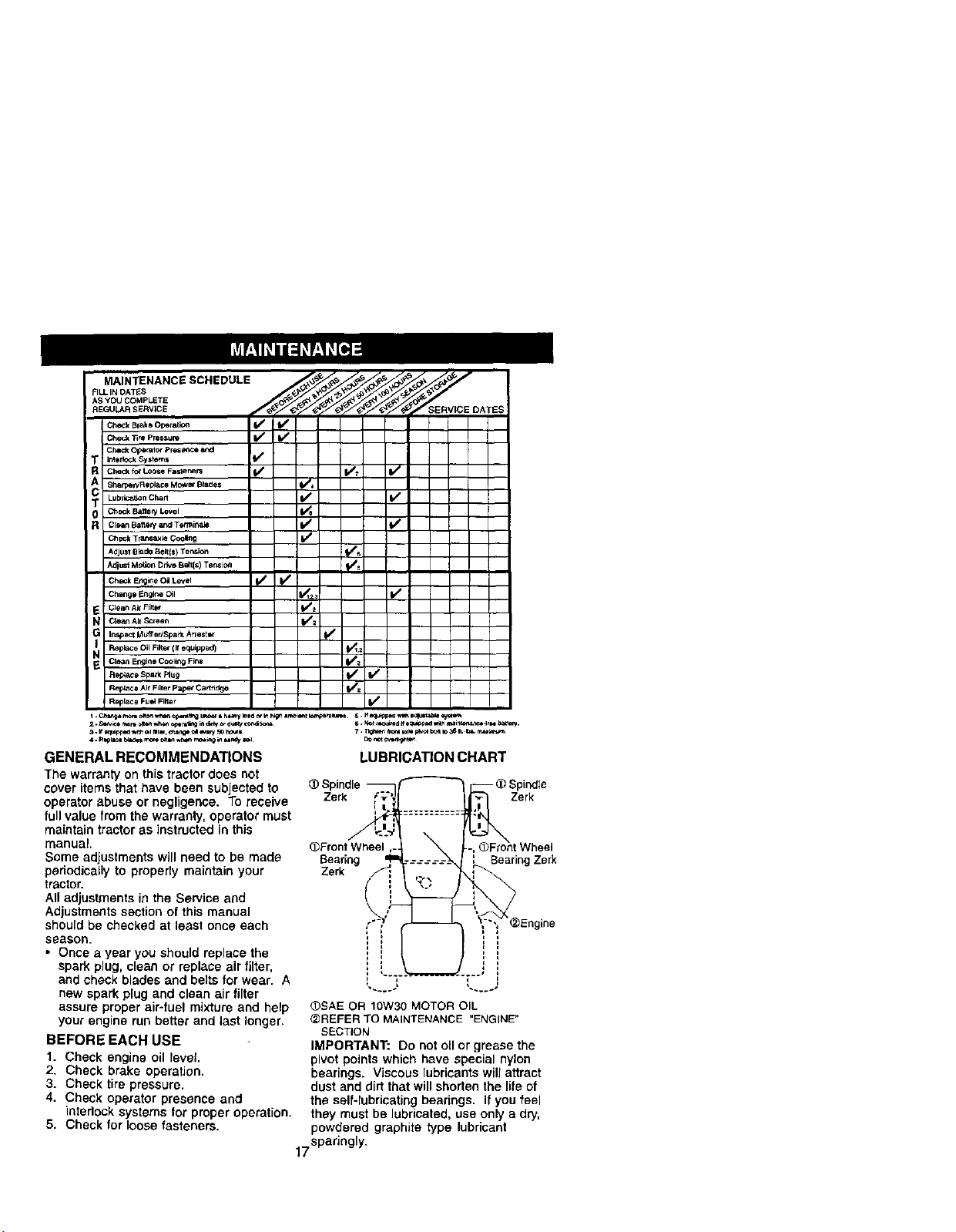
MAINTENANCESCHEDULE
_S YOU COMPLETE
REGUL_,R SERVICE _ERV;CE DATES
Che¢_ Blake Oporation _
Che_ "_ pmssure V' I/
CheCk _ralof prese,_;e a,,,:d
]r_erk_ Systerr_ k/
Check for Loose Fastenem _ _T If
Sl_rpelVReplace MoWS# Blade_ I_11_
Lu_rk;a_onchart If If
Ch_k Battery Level Vii
Clean Batte_ and Tetminab I1/
(_eck Trar,saxm Cooing I//
AdjUst 8lade _ell{$) Ten_ I_' s
AdjustMOtionDrk,eBali[s) Tension _
Check Engir_e O= Level _ V S
Clean Air Filter I11=
Clean Air Screen V/=
Replace Oil Filler ( ff equipped)
(_ean Engine COOling Firm _e
Re_e Air Filler paper Cao_l_e
Re_ce SPark Ptug _z If
Replace FIJ_ Fiber if
I. C_arlje mon_ _4teq w_ o_g U_ * h_Z_y _ltd o_ _ h_ &r_mt b*r,_ml. 5. ff equtpp_m ,t_h B_ _**'1_
2. ,_c_ m,o_eclte__,,ha_oper=_Tngin dmy _- dU_4y_
6. kLot =eq_d _ e_ad wilh tlmin_.lt =e _.
GENERAL RECOMMENDATIONS
The warrantyon this tractor does not
cover itemsthat have been subjected to
operatorabuse or negligence. To receive
full value fromthe warranty, operator must
maintain tractoras instructed in this
manual,
Some adjustmentswill need to be made
periodicallyto properly maintain your
tractor.
All adjustments in the Service and
Adjustments section of this manual
should be checked at least once each
seasoe.
• Once a year you should replace the
spark plug, clean or replace air filter,
and check blades and belts for wear. A
new spark plug and clean air filter
assure proper air-fuel mixture and help
your engine run better and last longer.
BEFORE EACH USE
1. Check engine oil level
2. Check brake operation.
3. Check tire pressure.
4. Check operator presence and
interlock systems for properoperation.
5. Check for loose fasteners.
LUBRICATION CHART
Spindle
Zerk Zerk
(_Front Wheel
Bearing Bearing Zerk
Zerk
(_SAE OR 10W30 MOTOR OIL
@REFER TO MAINTENANCE "ENGINE"
SECTION
IMPORTANT: Do not oil or grease the
pivot points which have special nylon
bearings. Viscous lubricants will attract
dust and dirt that will shorten the lile of
the self-lubricating bearings. If you feel
they must be lubricated, use only a dry,
powdered graphite type lubricant
17sparingly-
'_Engine
Page 18
TRACTOR
Always observe safety rules when
performing any maintenance.
BRAKE OPERATION
If tractor requires more than six (6) feet
stopping distance at high speed in
highest gear, then brake must be ad-
justed. (See "TO ADJUST BRAKE" in the
Service and Adjustments section of this
manual).
TIRES
• Maintain proper air pressure in all tires
(See =PRODUCT SPECIFICATIONS"
section of this manual).
• Keep tires free of gasoline, oil, or insect
control chemicals which can harm
rubber.
• Avoid stumps, stones, deep ruts, sharp
objects and other hazards that may
cause tire damage.
NOTE; Toseal tire punctures and prevent
flat tires due to slow leaks, tire sealant
may be purchased from your local parts
dealer. _re sealant also prevents tire dry
rot and corrosion.
OPERATOR PRESENCE SYSTEM
Be sure operator presence and interlock
systems are working properly. Ifyour
tractor does not function as described,
repair the problem immediately.
• The engine should not start unless the
clutcWbrakepedal is fully depressed
and attachement clutch controlis in the
disengaged position.
• When the engine is running,any
attempt by the operator to leave the
seat withoutfirst setting the parking
brake shouldshut off the engine.
• When the engine is running and the
attachment clutch is engaged, any
attempt by the operator to leave the
seat shouldshut off the engine.
• The attachment clutch should never
operate unless the operator is in the
seat.
BLADE CARE
Forbest results mower blades must be
kept sharp, Replace bent or damaged
blades.
BLADE REMOVAL
1. Raise mower to highest positionto
allow access to blades.
2. Remove hex bolt, lock washer and fiat
washer securing blade.
3. Installnew or resharpened blade with
trailing edge up towards deck as
shown. 18
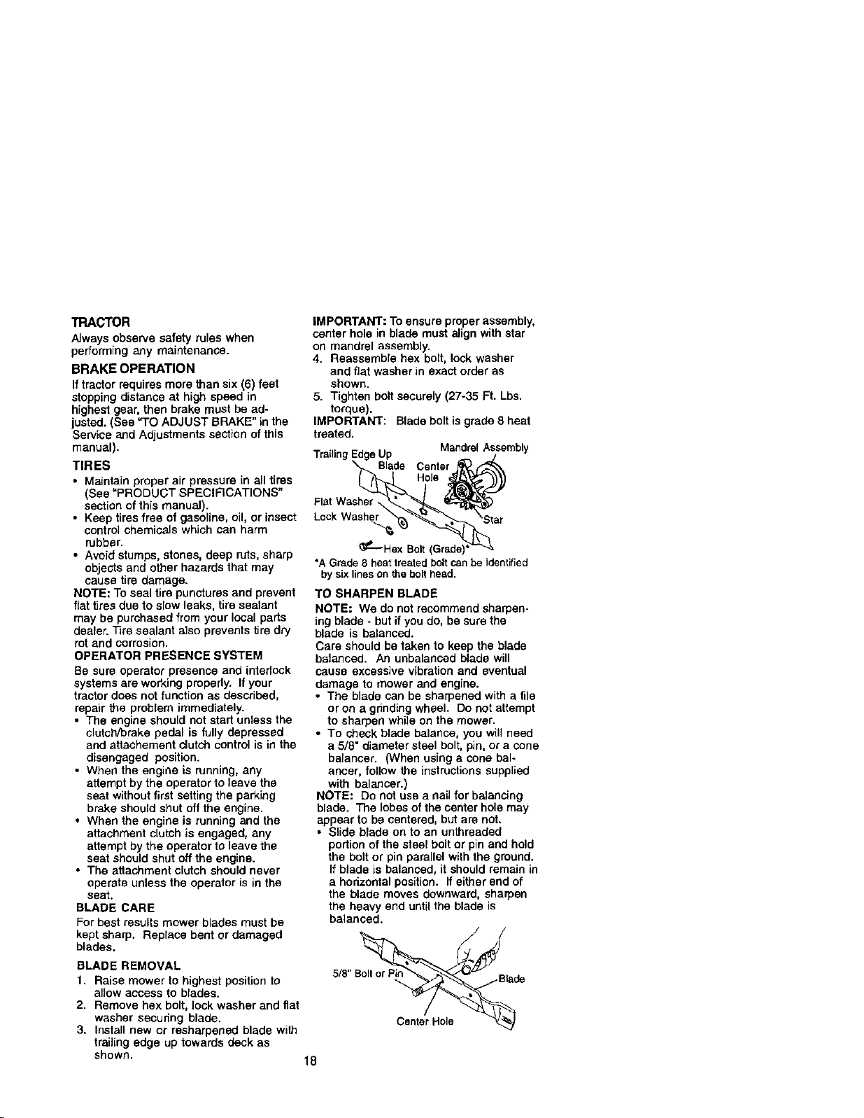
IMPORTANT: Toensure proper assembly,
center hole in blade mustalign with star
on mandrel assembly.
4. Reassemble hex bolt, lock washer
and fiat washer in exact order as
shown.
5. Tighten bolt securely (27-35 Ft. Lbs.
torque).
IMPORTANT: Blade bolt isgrade 8 heat
treated.
Trailing EdgeUp j
Blade Cenler j_('_
MandrelAssembly
_--Hex Bolt (Grade)*';'L'-'_-_"
*AGrade8 heattreatedboltcanbe identified
bysixlinesonthebolthead.
TO SHARPEN BLADE
NOTE: We do notrecommendsharpen-
ing blade - but if you do, be sure the
blade is balanced.
Care should betaken to keep the blade
balanced. An unbalanced blade will
cause excessive vibration and eventual
damage to mower and engine.
• The blade can be sharpened with a tile
oron a grindingwheel. Do not attempt
to sharpen while on the mower.
• To check blade balance, you will need
a 5/8" diameter steel bolt, pin,or a cone
balancer. (When usinga cone bal-
ancer, follow the instructions supplied
with balancer.)
NOTE: Do not use a nailfor balancing
blade. The lobes ofthe center hole may
appear to be centered, but are not.
• Slide blade on to an unthreaded
portionof the steel bolt or pinand hold
the bolt or pin parallel with the ground.
If blade is balanced, itshould remain in
a horizontalposition. If either end of
the blade moves downward, sharpen
the heavy end until the blade is
balanced.
Canter Hole
Page 19

BATTERY
Your tractorhas a batterychargingsystem
which is sufficientfor normaluse, How-
ever, periodiccharging ofthe batterywith
an automotive charger wiUextend its life.
• Keep battery and terminals clean.
• Keep batteryboltstight.
• Keep small vent holes open.
• Recharge at 6-10 amperes for 1 hour.
NOTE: The originalequipment battery on
your tractoris maintenancefree. Do not
attemptto open or remove caps orcovers.
Addingor checking level of electrolyte is
not necessary.
TO CLEAN BATTERY AND TERMINALS
Corrosion and dirt on the batteryand
terminalscan cause the battery to "leak"
power.
1. Open battery box door.
2. Disconnect BLACK battery cable first
then RED battery cable and remove
battery from tractor.
3. Rinse the battery with plain water and
dry.
4. Clean terminals and battery cable
endswith wire brush until bright.
5. Coat terminals with grease or petro-
leum jelly.
6. Reinstall battery (See "REPLACING
BATFERY" in the SERVICE AND
ADJUSTMENTS section of this
manual).
V-BELTS
Check V-belts for deterioration and wear
after 100 hours of operation and replace
if necessary. The belts are not adjustable.
Replace belts if they begin to slip from
wear.
TRANSAXLE COOLING
Keep transaxle free from build-up of dirt
and chaff which can restrict cooling.
ENGINE
LUBRICATION
Only use high quality detergent oil rated
withAPI service classificationSF-SJ
Selectthe oil'sSAE viscositygrade
according to your expected operating
temperature.
SAE V_SCO$1TY GF_OES
NOTE: Although multi-viscosity oils
(5W30, lOW30 etc.) improve starting in
cold weather, these multi-viscosity oils
will result in increased oi_consumption
when used above 32°E Check your
engine oil level more frequently to avoid
possible engine damage from running
low on oil.
Change the oil after every 25 hours of
operation or at least once a year if the
tractor is not used for 25 hours in one
year.
Check the crankcase oil level before
starting the engine and after each eight
(8) hours of operation. 37ghtan oilfill cap/
dipsticksecurely each time you check the
oil level
TO CHANGE ENGINE OIL
Determine temperature range expected
beforeoilchange. All oil must meet API
service classificationSF-SJ.
• Be sure tractor is on level surface.
• Oil will drain more freely when warm.
• Catch oil in a suitable container.
1. Remove oil fill cap/dipstick. Be careful
not to allow dirt to enter the engine
when changing oil.
2. Remove yellow cap from end of drain
valve and install the drain tube onto
the fitting.
OilDrainValve
Closed and
Position Drain
Tube
Yell
Cap_
3. Unlockdrain valve by pushinginward
slightly and turning counterclockwise.
4. To open, pull out on the drainvalve.
5. After oil has drained completely, close
and lockthe drain valve by pushing
inward and turning c_ockwiseuntil the
pin is in the locked position as shown.
6. Remove the drain tube and replace
the cap onto to the end of the drain
valve.
7. Refill engine with oil through oil fill
dipstick tube. Pour slowly. Do not
overfill. For approximate capacity see
"PRODUCT SPECIFICATIONS"
section of this manual.
8. Use gauge on oil fill cap/dipstickfor
checkinglevel. Be sure dipstickcap is
tightenedsecurely for accurate
reading. Keep oil at "FULL" line on
dipstick.
19
Page 20

CLEAN AIR SCREEN
Air screen must be kept free of dirtand
chaff to prevent engine damage from
overheating. Clean with a wire brush or
compressedair to remove dirt and
stubborndried gum fibers.
ENGINE COOLING FINS
Remove any dust,dirt or oil from engine
coolingfins to prevent engine damage
from overheating.
1. Remove screws from blower housing
and lift housingand dipstick tube
assembly off engine.
2. Cover oil fill opening to prevent entry
ofdirt.
3. Use compressed air or stiff bristle
brushto thoroughly clean engine
coolingfins.
4. To reassemble, reverse above
procedure.
Scre_ower Housing Screws
EngineCoolingFins Pu_rk
AIR FILTER
Your engine will not run propedy usinga
dirtyair filter. Clean the foam pre-cleaner
after every 25 hours of operation or every
season. Service paper cadridge every
100 hoursof operation or every season,
whichever occurs first.
Service air cleaner more often under
dusty conditions.
1. Remove knob(s) and cover.
TO SERVICE PRE-CLEANER
2. Slide foam pre-cleaner off cartridge.
3. Wash it in liquid detergent and water.
4. Squeeze it dry in a clean cloth.
5. Saturate it in engine oil. Wrap it in
clean, absorbent cloth and squeeze to
remove excess oil.
NOTE: Ifvery dirty or damaged, replace
pre-cleaner.
6. Reinstall pre-cleaner over cartridge.
7. Reinstallcover and secure with
knob(s).
TO SERVICE CARTRIDGE
1. Remove cartridge nut.
2. Carefully remove cartridge to prevent
debris from entedng carburetor.
Clean base carefully to prevent debris
from entering carburetor.
3. Clean cartridge by tapping gently on
fiat surface,
NOTE: ifvery dirty or damaged, replace
cartridge.
4. Reinstall cartridge, nut, precleaner,
cover and secure with knob(s).
IMPORTANT: Petroleumsolvents,suchas
kerosene,are notto be usedtocleanthe
cartridge.Theymaycausedeteriorationofthe
cartridge.DOnotoilcartridge.DOnotuse
pressurizedairto clean ordrycartridge.
Cover Knob _'_J_ Cover
B----..._Cartridge
Pre-Cleaner
Foam _ut
Cartridge
P_Lper
Base
MUFFLER
Inspect and replace corroded muffler and
spark arrester (if equipped) as it could
create a fire hazard and/or damage.
SPARK PLUGS
Replace spark plugs at the beginning of
each mowing season or after every 100
hours of operation, whichever occurs first.
Spark plug type and gap setting are
shown in "PRODUCT SPECIFICATIONS"
section of this manual.
IN-LINE FUEL FILTER
The fuel filter should be replaced once
each season. If fuelfilter becomes
clogged, obstructingfuel flow to carbure-
tor, replacement is required.
1. With engine cool, remove filter and
plug fuel line sections.
2. Place new fuel filter in positionin fuel
line with arrow pointingtowards
carburetor.
3. Be sure there are no fuel line leaks
and clamps are properly positioned.
4. Immediately wipe up any spilled
gasoline. Clamp
Clamp
FuelFil_
20
Page 21

CLEANING
• CEeanengine, battery, seat, finish,etc.
ofall foreignmatter.
• Keep finished surfaces and wheels free
ofall gasoline, oil, etc,
• Protect painted surfaces with automo-
We do not recommend using a garden
hose to clean your tractor unless the
electrical system, muffler, air filter and
carburetor are covered to keep water out.
Water in engine can result in a shortened
engine life,
thtetype wax.
CAUTION: BEFORE PERFORMING ANY SERVICE OR ADJUSTMENTS:
A
1. Depress clutch/brake pedal fully and set parking brake.
2. Place gearshift lever in neutral (N) position,
3. Place attachment clutch in"DISENGAGED" position.
4. Turn ignitionkey "OFF" and remove key.
5, Make sure the blades and all moving parts have completely stopped.
6. Disconnect spark plug wire from spark plug and place wire where it cannot
come in contactwith plug,
TRACTOR
TO REMOVE MOWER
Mower will be easier to remove from the
rightside of tractor.
1. Place attachment clutch in "DISEN-
GAGED" positim'_.
2. Move attachment lift lever forward to
lower mower to its lowest position.
3. Roll belt off engine pulley.
4, Remove small retainer spring, and lift
clutch spring off pulley bolt.
5. Remove large retainer spring, slide
collar off and push housing guide out
of bracket.
6. Disconnect anti-swayber from chassis
bracket by removing retainer spring.
7. Disconnect suspension arms from
rear deck brackets by removing
retainer springs.
8. Disconnect front links from deck by
9. Raise lift lever to raise suspension
arms. Slide mower out from under
tractor.
IMPORTANT: If an attachment other than
the mower deck is to be mounted on the
tractor, remove the front links and hook
the clutch spring Into square hole in
frame.
TO INSTALL MOWER
1. Raise attachment lift lever to its
highest position.
2. Slide mower under tractor with
deflector shield to rightside of tractor,
3. Lower lift leverto its lowestposition.
4. Install mower in reverse order of
removal instructions.
-r'_.
removing retainer spdngs.
Retainer !
Anti-Sway
Collar
Housing Guide
Large Retainer Spring
Small
Clutch Spri
Suspension Arms *-_
21
-""" ".""<''"_ SquareHole
Retainer Springs
(Both Sides)
Page 22

TO LEVEL MOWER HOUSING
Adjustthe mower while tractor is parked
on level groundor driveway. Make sure
tires are properly inflated (See "PROD-
UCT SPECIFICATIONS" section ofthis
manual). Iftires are over or
underinflated,you will not properly adjust
your mower.
SIDE-TO-SIDE ADJUSTMENT
• Raise mower to its highest position.
• At the midpoint of both sides of mower,
measure height from bottom edge of
mower to ground. Distance =A"on
both sides of mower should be the
same or within 1/4" of each other.
• If adjustment is necessary, make
adjustment on one e_deof mower only.
• To raise one side of mower, tighten lift
link adjustment nut on that side.
• To lower one side of mower, loosen lift
link adjustment nut on that side.
NOTE: Each full turn of adjustment nut
will change mower height about 1/8".
Recheck measurements after adjust-
ing.
Bottomedge of Bonomedge of
mowerto ground mowerto ground
Check adjustment on rightside of tractor.
Measure distance "D" directlyintrent and
behind the mandrel at bottom edge of
mower housing as shown.
• Before making any necessary adjust-
ments, check that both front linksare
equal in length.
• If links are not equal in length, adjust
one link to same length as other link.
• To lower front of mower Ioosan nut "E"
on both front links an equal number of
turns.
• When distance "D" is 1/8" to 1/2" lower
at front than rear, tightennuts =F'
against trunnion on both front links.
• To raise front of mower, loosen nut "F"
from trunnion on both front links,
Tighten nut "E" on both front links an
equal number of turns.
• When distance "D" is 1/8" to 1/2" lower
at front than rear, tighten nut "F" against
trunnionon both front links.
• Recheck side-to-side adjustment.
andrel
BothFrontLinksShouldbeEqualin Length
rm
FRONT-TO-BACK ADJUSTMENT
IMPORTANT; Deck must be level side-to
side. If the following front-to-back adjust-
ment is necessary, be sure to adiust both
front links equallyso mower will stay level
side-to-side.
Toobtain the best cutting results,the
mower housing should be adiusted so
that the front is approximately 1/8" to 1/2"
lower than the rear when the mower is in
its highest position.
Nut"F"_ut =E"
Trunnion
22
Page 23

TO REPLACE MOWER BLADE DRIVE
BELT
The mower blade drive belt may be
replaced withouttools. Park the tractor on
level surface. Engage parking brake.
BELT REMOVAL -
1. Remove mower from tractor (See "TO
REMOVE MOWER" in this section of
this manual).
2. Work belt off both mandrel pulleys and
idler pulleys.
3. Pull belt away from mower.
BELT INSTALLATION -
4. Install new belt in reverse order of
removal.
5. Make sure belt is in all pulley grooves
and inside all belt guides.
6. Install mower in reverse order of
removal instructions.
Mandrel
Pulley Idler
Pulley
TO ADJUST BRAKE
Your tractor isequipped with an adjust-
able brake system whichis mounted on
the rightside ofthe transaxle.
If tractorrequires more than six(6) feet
stoppingdistance at high speed in
highestgear on a level dry concrete or
paved surface, then brake must be
adjusted.
1. Depress clutch/brake pedal and
engage parking brake.
2. Measure distance between brake
operatingarm and nut "A"on brake
rod.
3. If distanceis other than 1-t/2",loosen
jam nut and turn nut"A"until distance
becomes 1-1/2". Retightenjam nut
against nut "A".
4. Road test tractor for proper stopping
distanceas stated above. Readjust if
necessary. If stopping distance is still
greater than six (6) feet in highest
gear, further maintenance is neces-
sen/. Contact a Sears or other
qualified service center.
With ParkingBrake "Engaged"
\ Nut"A"
_ _ Nut
Operating
TO REPLACE MOTION DRIVE BELT
Park the tractoron level surface. Engage
parking brake. For assistance, there isa
belt installationguide decal on bottom
side of leftfootrest.
1. Remove mower (See "TO REMOVE
MOWER" in this section of this
manual.)
2. Remove belt from stationary idler and
clutching idler.
3. Pull belt slack toward rear of tractor.
Remove belt upwards from transaxle
pulley by dellecting belt keepers.
4. Pull belt toward front of tractor and
remove downwards from around
engine pulley.
5. Install new belt by reversing above
procedure,
Engine Pulle
Clutchin{
Stationary Idler
Transaxle
23
Page 24

TO ADJUST STEERING WHEEL ALIGN-
MENT
If steedng wheel crossbam are not
horizontal(left to dght) when wheels are
positionedstraight forward, remove
steedng wheel and reassemble per
instructionsin the Assembly section of
this manual.
FRONT WH EEL TOE-IN/CAMB ER
The front wheel toe-in and camber are
notadjustableon yourtractor. If damage
has occurredto affect the front wheel toe-
inor camber, contact a Sears or other
qualified service center.
TO REMOVE WHEEL FOR REPAIRS
1. Slack up axle securely.
2. Remove axle cover, retaining ring and
washers to allow wheel removal (rear
wheel contains a square key- Do not
lose).
3. Repair tire and reassemble.
NOTE: On rear wheels only: align
grooves in rear wheel hub and axle.
Insertsquare key.
4. Replace washers and snap retaining
ring securely in axle groove.
5. Replace axle cover.
NOTE: Toseal tire punctures and prevent
flat tires dueto slowleaks, tire sealant
may be purchased from your local parts
deaEer.Tire sealant also prevents tire dry
rot and corrosion.
Washers
Retainin
Ring
Axle
Cover
TO START ENGINE WITH A WEAK
BATTERY
_CAUTION: Lead-acidbattadesgenerate
explosivegases. Keepsparks,flameand
smokingmaterialsaway from batteries.
Always weareyeprotectionwhen around
batteries.
Ifyour batteryistooweak tostarttheengine,it
shouldbe recharged.(See "BATTERY"inthe
MAINTENANCEsect_n ofthismanual).
If"jumper cables"areusedfor emergency
starting,follow thisprocedure:
IMPORTANT: Yourtractoris equipped witha
12voltnegativegroundedsystem.The other
vehlealmustalsobe a 12volt negative
groundedsystem.Donotuseyourtractor
batteryto startothervehicles.
TO ATTACHJUMPER CABLES -
1. Connect each end of the RED cable to
the POSITIVE (+) terminal of each
battery, taking care notto short
against chassis.
2. Connect one end of the BLACK cable
to the NEGATIVE (-) terminal of fully
charged battery.
3. Connect the other end of the BLACK
cable to good CHASSIS GROUND,
away from fuel tank and battery.
TO REMOVECABLES, REVERSE ORDER-
1. BLACK cable first from chassis and
then from the fully charged battery.
2. RED cable last from both batteries.
Positive Terminal Negative Terminal
Square Key
(RearWheel Only)
24
Terminal
Battery
ative
Terminal
Page 25

REPLACING BATTERY
J_I,CAUTION: DOnot short battery
terminalsby allowinga wrench or any
otherobject tocontact both terminals at
the same time. Before connectingbattery,
remove metal bracelets, wristwatch
bands, rings, etc.
Positiveterminal must be connected first
to prevent sparking from accidental
grounding.
1. Lift seat pan to raisedpositionand
open battery box door.
2. Disconnect BLACK battery cable first
then RED battery cable and carefully
remove batteryfrom tractor.
3. Install new battery with terminals in
same positionas old battery.
4. Firstconnect RED battery cable to
positive (+) terminal with hex bolt and
keps nut as shown. Tighten securely.
5. Connect BLACK grounding cable to
negative(-) terminal with remaining
hexbolt and keps nut. Tighten
securely.
6. Close battery box door.
Battery
Box
INTERLOCKS AND RELAYS
Looseor damagedwidngmay cause your
tractorto run poody,stoprunning, or
prevent it fromstarting.
• Check wiring. See electrical widng
diagram in the Repair Parts section.
TO REPLACE FUSE
Replace with 20 amp automotive-type
plug-in fuse. The fuse holder is located
behind the dash.
TO REMOVE HOOD AND GRILL AS-
SEMBLY
1. Raise hood.
2. Unsnap headlightwire connector.
3. Stand infront oftractor. Grasp hood at
sides, tilttoward engine and liftoff of
tractor.
4. To replace, reverse above procedure.
Heandn[iegchttoWire
_ Hood
Posi'dve Negative
(Red) Cable (Black) Cable
TO REPLACE HEADUGHT BULB
1. Raise hood.
2. Pull bulb holder out of the hole in the
backside of the grill.
3. Replace bulb in holder and push bulb
holder securely back into the hole in
the backside of the gd]l.
4. Close hood.
ENGINE
Maintenance, repair, or replacement of
the emission controldevices and sys-
tems, which are beingdone at the
customers expense, may be performed
by any non-road engine repair establish-
olt
ment or individual. Warranty repairs must
be performed by an authorized engine
manufacturer's service outlet.
TO ADJUST THROTTLE CONTROL
CABLE
The throttlecontrolhasbeen presetat the
factoryand adjuslment shouldnotbe
necessary. Checkadjustment asdeschbed
belowbefore looseningcable. If adjustment
isnecessary,proceedas follows:
t. With engine notrunning,move throttle
control lever from slow to choke position.
Slowly movelever from choke tofast
position.
25
Page 26

2. Check that holes "A" in governor control
lever and hole in governor plate line-up.
If holes "A" are not aligced, loosen clamp
screw and move throttle cable until holes
are aligned. T_ghten clamp screw
sscurely.
Governor Control Lever Control Plate
Governor
\
Holes
=A"
TO ADJUST CARBURETOR
NOTE: The carburetoronthis engineis low
emission. It is equippedwith anidlefuel
adjustingneedle witha limifer cap, which
allows some adjustmentwithinthe limits
allowedbythe cap. Donotattemptto remove
the limitercap. "me limitercap cannot be
removed without breaking the adjusting
needle.
The carburetor has been presetatthe factory
andedjus'_mentshould not be necessary.
However,minor a_ustmentmay be required
tocompensatefordifferencesinfuel,
temperature,eltRudeor load. Ifthe carburetor
doesneed adjustment, proceed as follows:
In general,tuming idle mixturevalve in
(clockwise)decreases the supply of fuel to
the enginegiving a leaner fuel/air mixture.
Turningthe idlemixturevalveout (counter-
clockwise)increasesthesupply of fuel to the
engine giving a richer fuel/air mixture.
IMPORTANT: Damage to the needle valve
andthe seatin carburetormay result ifscrew
istomed in too tight.
PRELIMINARYSETTING -
1. Aircleaneressembly must be assembled
tothe carburetor when making carburetor
a_nstrnents.
2. Be sure the throttle control cable is
adjusted properly (see above).
Clamp Screw hrottle
Cable
FINALSETTING-
1. Start engine andallowto warm forfive
minutes. Makefinala_ustments with
engine runningand shifl/roctJoncontrol
leverin neutral(N) pesition.
2. Movethretleonntrd leverto slow
pesi_on.W_ finger, rotate endhold
throttle lever against idlespeed screw.
Turn _ speed screwto attain 1750
RPM.
3. While still holdingthrottle lever against
idle speed screw,tom idlemixturevalve
full travel deskwisethencounterdeck-
wise un'dlengineruns rough. "rum valve
to a point m_dwaybetween thosetwo
pnsi_ons. Releasethrottlelever.
ACCELERATIONTEST -
4. Movethrotlte contrellever from slowto
fast position. If engine hesitatesordies,
tum idle mixture valve out (caunterdock-
wise) fi8tum. Repeattest and conlnue
to adjust, if necessary,untilengine
accelerates smoothly.
Highspeed stop isfactoryadjusted. Do not
ac_ust- damage may result.
IMPORTANT: Nevertamper withthe engine
governor,which isfactorysetfor proper
engine speed. Overspeedingthe engine
above the factoryhighspeed setting can be
dangerous,ff you think_ engine_ovemed
high speed needsa_usting, contact a
Sears or other qualified service center,
which has proper equipment and experience
to make any necessary adjustments.
Idle!
Lever
IdleMixture
Ire with
26
Page 27

Immediately prepare your tractor for
storage at the endof the season or if the
tractor will not be used for 30 days or
more.
_CAUTION: Never storethe tractor with
gasoline in the tank inside a building
where fumes may reach an open flame or
spark. Allow the engine to cool before
storing in any enclosure.
TRACTOR
Remove mower from tractor for winter
storage. When mower is to be stored for
a period of time, clean it thoroughly,
remove all dirt, grease, leaves, etc. Store
in a clean, dry area.
t. Clean entiretractor (See =CLEANING"
in the Maintenance sectionof this
manual).
2. Inspect and replace belts, if necessary
(See belt replacement instructions in
the Service and Adjustments section
of this manual),
3. Lubricate as shown in the Mainte-
nance section of this manual.
4. Be sure that all nuts, bolts and screws
are securely fastened. Inspect moving
parts for damage, breakage and wear.
Replace if necessary.
5. Touch up all rusted or chipped paint
surfaces; sand lightly before painting.
BATrERY
• Fully charge the batteryfor storage.
• After a period of time in storage,battery
may require recharging.
• To help prevent corrosionand power
leakage during long periods of storage,
batterycabtes should be disconnected
and battery cleaned thoroughly (see
"TO CLEAN BATTERY AND TERMI-
NALS"in the Maintenance sectionof
this manual).
• After cleaning, leave cables discon-
nected and place cables where they
cannot come in contact with battery
terminals.
• If batteryis removedfromtractorfor
storage, do not store batterydirectlyon
concrete or damp surfaces.
ENGINE
FUEL SYSTEM
IMPORTANT: It is important to prevent
gum depositas from forming in essential
fuel system parts such as carburetor,fuel
hose, or tank during storage. Also,
experiance indicates that alcohol
blended fuels (called gasohol or using
ethanol or methanol) can attract moisture
which leads to separation and formation
of acids dudng storage. Acidic gas can
damage the fuel system of and engine
while in storage.
1. Drain the fuel tank.
2. Start the engine and let it run until the
fuel lines and carburetor are empty.
• Never use engine or carburetor cleaner
products in the fuel tank or permanent
damage may occur.
• Use fresh fuel next season.
NOTE: Fuel stabilizer is an acceptable
alternative in minimizing the formation of
fuel gum deposits during storage. Add
stabilizer to gasoline in fuel tank or
storage container. Always follow the mix
ratio found on stabilizer container. Run
engine at least 10 minutes after adding
stabilizer to allow the stabilizer to reach
the carburetor, Do not drain the gas tank
and carburetor if using fuel stabilizer.
ENGINE OIL
Drain oil (with engine warm) and replace
with clean engine oil. (See "ENGINE" in
the Maintenance section of this manual).
CYUNDER(S)
1. Remove spark plug(s).
2. Pour one ounce of oil through spark
plug hole(s) into cylinder(s).
3. Turn ignitionkey to =START" position
for a few seconds todistributeoil.
4. Rep]ace with new spark plug(s).
OTHER
• Do not store gasoline from one season
to another.
• Replace your gasoline can if your can
starts to rust. Rust and/or dirt in your
gasoline will cause problems.
• If possible, store your tractor indoors
and cover it to give protectionfrom dust
and dirt.
• Cover your tractor with a suitable
protective cover that does not retain
moisture. Do not use plastic. Plastic
cannot breathe which allows conden-
sation to form and will cause your
tractor to rust.
IMPORTANT: Never cover tractor while
engine and exhaust areas are still warm.
27
Page 28

TROUBLESHOOTING CHART
PROBLEM CAUSE CORRECTION
Will not start
Hard to start
1. Out of fuel.
2. Engine not "CHOKED"
properly.
13. Engine flooded.
4. Bad spark plug.
5, Dirty airfilter.
6. Dirty fuel filter,
7 Waterin fuel,
8. Looseor damaged wiring.
9. Carburetor outof adjustment
10, Engine valves outof
adjustment.
1. Dirty air filter.
2. Bad spark plug.
3. Weak or dead battery.
4, Dirty fuel filter.
5. Stale ordidyfuel.
6, Loose or damaged wiring,
7. Carburetor out of adjustment.
8. Engine valves out of
adjustment.
1. Fill fuel tank.
2. See "3"0 START ENGINE"
in Operation secltoo,
3. Wait several minutes
before attempting to stad,
4. Replace spark plug.
5, Clean/replace air filter.
6. Replace fuel filter.
7. Drain fuel tank and
carburetor, refill tank with
fresh gasoline and replace
fuel filter.
8, Check all wiring.
9, See "To Adjust Carburetor"
in Service Adjustments
section.
1O.Contact a Sears or other
qualified service center.
1, Clean/replace air filter,
2. Replace spark plug.
3. Recharge or replace
battery,
4. Replace fuel filter.
5. Drain fuel tank and refill
with fresh gasoline.
6. Check all wiring.
7. See "To Adjust Carburetor"
in Service Adjustments
section.
8. Contact a Sears or other
qualified service center,
Enginewill not
turn over
Engine clicks but
will not start
1. Brake peda_ not depressed.
2. Attachment dutch is
engaged,
3. Weak or dead battery.
4. Blown fuse.
5. Corroded battery terminals.
6. Loose or damaged wiring.
7. Faulty ignition switch.
8. Faulty solenoid or starlet.
9. Faulty operator presence
switch(es).
1. Weak or dead battery.
2. Corroded battery terminals.
3. Loose or damaged wiring.
4, Faultysolenoid or starter,
28
1. Depress brake pedal.
2. Disengage attachment
clutch.
3, Recharge or replace
battery.
4. Replace fuse.
5. Clean battery terminals.
6. Check all wiring.
7, Check/replace ignition
switch,
8. Check/replace solenoid or
starter,
9. Contact a Sears or other
qualified service center.
1. Recharge or replace battery.
2. Clean battery terminals.
3. Check all wiring.
4. Check/replace solenoid or
starter.
Page 29

TROUBLESHOOTING CHART
PROBLEM CAUSE CORREC_ON
Lossofpower 1. Cu_ingtoo muchg_s_oo
fast.
2. Throttle in "CHOKE"
1. Set in "Higher Cut" position/
reduce speed.
2. Adjust throttle control.
position.
3. Build-up of grass, leaves
and trash under mower.
4. Dirty air filter.
5. Low oil level/dirty oil.
6. Faulty spark plug.
3. Clean underside of mower
housing.
4. Clean/replace air filter.
5. Check oil level/change oil.
6. Clean and regap or change
spark plug.
7. Dirty fuel filter.
8. Stale ordirty fuel.
7. Replace fuel fi]ter.
8. Drain fuel tank and refill with
fresh gasoline.
9. Water in fuel.
g. Drain fuel tank and carbure-
tor, refill tank with fresh
gasoline and replace fuel
filter.
10.Spark plug wire loose.
10.Connect and tighten spark
plug wire.
11.Dirty engine air screen/fins.
12.Dirty/clogged muffler.
13. Loose or damaged wiring.
14.Carburetor out of
adjustment.
11.Clean engine air screen/fins.
12.Clean/replace muffler.
13.Check all widng.
14.See "To Adjust Carburetor"
in Service Adjustments
section.
15.Contact a Sears or other
qualified service center.
1. Replace blade.
Tighten blade bolt.
2. Replace blade mandrel.
3. Tighten loose part(s).
Excessive
vibraUon
15.Engine valves out of
adjustment.
1. Worn, bent or loose blade.
2. Bent blade mandrel.
3. Loose/damaged part(s).
Replace damaged parts.
Engine continues
to run
when operator
leaves seat with
with attachment
clutch engaged
Poorcut-uneven
1. Faulty operator-safety
presence control system.
1. Worn, bent or loose blade.
2. Mower deck not level.
3. Buildup of grass, leaves,
and trash under mower.
4. Bent blade mandrel.
5. Clogged mower deck vent
holes from buildup of
grass, leaves, and trash
around mandrels.
29
1. Check wiring, switches and
connections. If not
contact a Sears or other
qualified service center.
1. Replace blade. Tighten
blade bolt.
2. Level mower deck.
3. Clean underside of mower
housing.
4. Replace blade mandrel.
5. Clean around mandrels to
open vent holes.
Page 30

TROUBLESHOOTING CHART
PROBLEM CAUSE CORRECTION
Mowerbladeswill 1. Obstruction in clutch 1. Remove obstruction.
not rotate mechanism.
2. Worn/damaged mower 2. Replace mower drive belt,
drive belt.
3. Frozen idler pulley. 3. Replace idler pulley,
4. Frozen blade mandrel. 4, Reptace blade mandrel.
Poor grass 1, Engine speed too slow.
discharge
2. Travel speed too fast,
3. Wet grass.
1. Place throttle controlin
"FAST" position.
;2. Shiftto slower speed.
3. Allow grass to dry before
mowing.
4. Mower deck not level.
5. Low/uneven tire air
pressure.
6. Worn, bent or loose blade.
i7. Buildup of grass, leaves
and trash under mower.
B, Mower drive belt wom.
9. Blades improperly installed.
10.Improper blades used.
11.Clogged mower deck vent
holes from buildup of grass,
4. Level mower deck,
5. Check tires for prober air
pressure.
6. Replace/sharpen blade.
Tighten blade bolt.
7. Clean underside of mower
housing.
8. Replace mower drive belt.
9. Reinstall blades sharp edge
down.
10.Replace with blades listed
in this manual.
11.Clean around mandrels to
open vent holes.
leaves, and trash around
mandrels.
Headlight(s) not
working
if so equipped)
Battery will not 1.
charge 2.
1. Switch is "OFF". 1.
2. Bulb(s)or lamp(s) burned out. 2.
3. Faulty light switch. 3,
4. Loose or damaged wiring. 4.
Blown fuse.
5.
Bad battery cell(s).
Poor cable connections.
3.
Faulty regulator 3.
Turn switch"ON".
Replace bulb(s) or lamp(s).
Check/replace light switch.
Check wiring and connec-
tions.
5.
Replace fuse.
1.
Replace battery.
2.
Check/clean all connec-
tions.
Replace regulator.
(if so equipped).
4.
Faulty alternator. 4. Replace alternator.
Engine"backfires" 1.
whenturning
engine"OFP'
Engine throttle control not 1. Move throttle control to
set at "SLOW" position "SLOW" position and allow
for 30 seconds before to idle for 30 seconds before
stopping engine, stopping engine,
30
Page 31

SCHEMATIC
AMMETER
(OPTIONAL)
TRACTOR - MODEL NUMBER 917.271532
JilriJ
BATTERY
FUE
DIODE =ALTERNATOR
IGNITION SWITCH
OFF _AI N_II=
IGHT B+A1 A2+L
I++.I
YOUR TRACTOR IS _. __ _ =_._,
EC_UIPP ED WlTt-_ A SPECIAL
ALTERNATOR SYST_M_
CONNECTED TO THE
OWN ELECTRiC,_I_ SOURCE_ HEADLiGNT-C;
WiLL CHANGE WiTH ENGINE
WiLL BECOME THEIR SRJGHTJEST_
NOTE l
TRE LIGHTS ARE NOT
EATTERY_ BUT HAVE THEIR
BEO,_,USE OF TRIS_ THE
SR_GHTNESS OF TRE LIGHTS /_
SPEED. AT iDLE THE LtGHTS
WJLL OIM_ AS THE ENGINE IS NCN_REMOVABLE
SPEEDED UP_ THE LIGHTS CONNECTIONS
REMOVABLE
WIRING INSULATED CUPS
NOTE: IF WIRING INSULATED CLIPS WERE REMOVED FOR
SERVICING OF U_IT, THEY SHOULD BE REPLACED TO
PROPERLY SECURE YOUR WIRING,
CONNECTIONS
31
Page 32

ELECTRICAL
TRACTOR- MODELNUMBER917.271532
32
i
Page 33

ELECTRICAL
TRACTOR - MODEL NUMBER 917.271532
KEY PART
NO. NO. DESCRIPTION
1 144925 Battely 12 Volt 25 AMP
2 74760412 Bolt Hex Hd I/4-20unc X 3/4
8 156417 Case Battery
16 153664 Switch _ntedock Push-In
21 166181 Harness Socket Light W/4152J
22 4152J Bulb Light #1156
24 4799,} Cable Battery 6ga 11• red
25 146147 Cable Battery 6 Ga W/t6 Wir red
26 175158 Fuse 20 AMP
27 73510400 Nut Keps Hex 1/4-20 Unc
28 4207J Cable Ground 6ga 12" black
29 121305X Switch Plunger Nc Gray
30 175566 Switch Ign Delta Push-In
33 140403 Key Ign Molded Craftsman, Delta
40 178437 Hamess IgrL
41 71110408 Bolt BIk Hex 1/4-20unc x 1/2
42 131563 Cover Terminal Red
43 178861 Solenoid
45 t21433X Ammetar Rectangular 5 AMP
52 141940 Protection Wire Loop
NOTE: All component dimensions given inU. S.
inches 1 inch = 25.4 mm
33
Page 34

TRACTOR - MODEL NUMBER 917.271532
CHASSIS AND ENCLOSURES
3O
29
v 12 28
28 25 _*,5 5 53 1 2 SS
26
33
10
3 2S
3
I
35
208
38
34
Page 35

TRACTOR - MODEL NUMBER 917.271532
CHASSIS AND ENCLOSURES
KEY PART
NO. NO. DESCRIPTION
1 174620 Chassis Lt Stamping
2 176554 Dmwba#
3 17060612 Screw 3/8-16 x 3]4
5 155272 BumperHood/Dash
6 174643X010 Saddle SLKSCRE FLTSDL
8 126471X Clip Insulator .406 Mtg Hole
9 168348X010 Dash SlkScr PIm Mesh Sym
10 72140608 Bolt RdHd Sqnk. 3/9-16 x 1
11 155927 Panel Asm. Dash Lh
12 145660 Clip Tinnerman G rillsP/L
13 172107X010 Panel Dash Rh
15 74180512 Screw Mach Trhd 5/16-18unc x 3/4
16 73510500 Nu Keps5/16-18unc
17 159639X558 Hood Pnt Steel PriVate Label
19 126938× Bumper HOOd
24 74780618 Bolt Fin Hex 3/8-16 Uric x t Gr. 5
25 19131312 Washer 13/32 x 13/16 x 12 Ga.
26 78800600 Nut LockHex w/Ins 3/8-16 Unc
28 140434 GrilVLens Asm
29 140273)(599 Lens Gdlle
30 169465X558 Fender Pnt
31 136619 Bracket Fender Support
33 145244X558 Footrest Pnt. Lh
34 145243X558 Footrest Pnt. Rh
35 72110606 BORRdHd Sht. Sqnk, 3/8-16 x 3/4
37 17490509 ScrewThdrol 5/16-18 x 1/2 Tyt
38 175710 Bracket Asm. Pivot Mower Rear
51 738C0400 Nut Lock Hex W/ins. 1/4-20
52 19091416 Washer 9/32 x 7/B x 16 Ga,
53 144697 Bracket Grille LH
54 161464 Borew Hex Wshd #8-18 x 7/8
55 144696 Bracket, Gdlle RH
57 74780412 Bolt Fin Hex 1/4-20 x 3/4
58 150127 Air Duct Private Label LT Engine
t45 156524 Rod Pivot Chassis/Hood
205 17490608 Screw Thdrol 3/8-16 x 1/2
206 170165 Bolt Shoolder _/16-18 TT
208 17670608 Screw T]ndrol. 3/8-16 x 1/2
209 17000612 Screw Hex Wsh Todml 3/8-16 BL
212 156229 Insert Lens Reflective
NOTE: A_Icomponent dimensions givenin U. S.
inches 1 inch = 25.4 mm
5479J Plug Sutton BIk .359 Oia. Choke
35
Page 36

GROUND DRIVE
TRACTOR - MODEL NUMBER 917.271532
36
Page 37

GROUND DRIVE
TRACTOR - MODEL NUMBER 917.271532
KEY PART KEY PART
NO. NO. DESCRIPTION NO. NO, DESCRIPTION
1 .... Transaxle(SeeBreakdown) 50 _3715 Bolt Hex Hd 3/8-16unc x 1-1/2
2 146682 Spchg Return Brake T/a Zinc 52 STDr-_1431 Nut Crown Lock 5/16o18
3 123666X Pulley Trap,saxle 18/20" tires 53 105710X LinkClutch 7 66
4 12000028 RingRetainer # 5100-62 55 105709X Bpdng Return Clutch 6 75
5 121520X StrapTorque3ODegrees 56 17060616 Screw 3/8-16 x 1
6 17060512 Screw 5/16-18 x 3/4 57 160855 V-Belt Gd Drive
7 162240 Bracket Saddle Shift Tla 59 169691 Keeper BeltCenterspan
8 131679 Rod Shf Sdl LY/YT Sir BIkZinc 61 17060612 Screw 5/8-16 x 3/4
10 STD561210 Pin Cotter 1/5 x 1 Cad 62 8883R Cover Pedal BIkRound
11 105701X Washer Plate Shf 358 Sq Hole 63 175410 Pulley Eng
12 10151216 Washer 15/32 x 3/4 x 16ga 64 71170764 Bolt Hex 7116-20 x 4 Gr 5
t3 74550412 Bolt1/4-28unf Gr8 W/Patch 65 STC551143 Washer Lock HW HlelBpr 7/16
14 $31_551125 Washer Lock Hvy Helical 1/4 66 154778 Keeper Belt Engit_e
15 74490544 BoltHex FLGHD 5/16-15 Gr.5 70 134683 Guide Belt Mower Dr_,eRH
18 BTD523710 Bo6 Fin Hex 3/8-16 x 1 74 109502X Spacer Axle
19 $30341437 Nut Lock Hex W/Ins. 3/8-16 Unc 75 121740X Washer 25/32 x 1 1/4 x 16 Ga
21 106933X Knob Rd 1/2-13 PlstcThds BIk 75 STD581075 E-ring#5133-75
22 130804 Rod Brake BIk Zinc 26 840 77 123583X Key Square 2 0 x 1845/1865
24 STD541237 Nut Hex Jam 3/8-16 Uric 78 121748X Washer 23/32 x 1-5/8 x 16 Ga
25 106888X Spdng Rod Brake 2 O0 Zinc 79 2228M Key
27 STD581210 Pin Cotter 1/8 x 3/4 Cad 96 4497H Retainer Spring 1.00
28 175765 Rod Brake Parking LI/Yt 112 19091210 Washer 9/32 x 3/4 x 10 Ga
29 71673 Cap Brake Parkleg 113 127285X StrapTorque
30 174973 Bracket Mtg Trar,.saxle 116 72140608 Bolt Rdhd Sq Neck 3,/8-16 x 1
39 STD523107 BottRexHdsi16*18uncx3/4 119 19131016 Washer13!32 x 5/8 x16 Ga
34 175575 Shaft Asm Pedal Foot 120 73900600 Nut Lock Rg 3/8-16
35 120183X Bearing Nylon Blk 6291d 150 174456 SpacerRetaleer
36 BTD551662 Washer 21/32 x 1 x 16 Ga 151 10133210 Washer 13/32 x 2 x 10 Ga
37 BTD571810 Pin Rol13/16 x l" 170 178394 KeeperBeltTransaxle
38 179114 PulleyIdler Composite Ext Hub 202 72110614 BoRCarr Bh 3/8-16 x 1-3/4 Gr, 5
39 7476C648 BoltFin Hex 3/6-16 Unc X 3 212 145212 NutHex Flange Lock
41 175556 Keeper Belt Idler
47 127783 Pulley Idler V Groove Plastic
48 154407 Bellcrank Clutch Gm Dry sg NOTE: All component dimensions given in U. S.
49 123205X Retainer Belt Style Spdng inches 1 inch = 25.4 mm
Dana4360-140 51 STD541437 NutCrownlock 3/8-16UNC
37
Page 38

STEERING
TRACTOR- MODELNUMBER917.271532
38
/
Page 39

STEERING
TRACTOR - MODEL NUMBER 917.271532
KEY
PART
NO.
NO. DESCRiPTiON
1
139768 Wheel Steedng Opp Sears BIk
2
175131 Axle Asm Front
3
169840 Spindle Asm Lh
4
1698.39 Spindle Asm Rh
5
_66H Washer Thrust .75 x 1.230
121748)( Washer 25/32 x 1-5/8 x 16 Ca+
6
7
19272016 Washer 27/32 x 1-1/4 x 16 Ca.
8
12000029 RingXlip#T5304-75
9
3366R Bearing Col Strg BIk
lO
175121 Dragtink
11
10040600 Washer Lock FIvy Hlcl Spr 3/5
13
136518 Spacer Brg Axle Front
15
145212 Nut Hexflange Lock
17
177576 Shaft Asm Strg
26
126847X BushingLink Drag BIkLR
19131416 Washer 13/32 x 7/8 x 16 Ca.
28
29
17060612 Screw 3/8-16 x 3/4
3O
STD561210 Pin Cotter 1]4 x 3/4
32
130465 Rod Tie Wire Form 19.75 Mech
36
155099 Bushing Sttg, 5/8 ID Dash
37
152927 S_ew
38
139769 Cap Wheel Steer Opp Sears USA
19133812 Washer 13/32 x 2-318x 12 Ca,
39
4O
7810H Nut Lock Center 3/8-24
41
100711L Adaptor Wheel Strg.
42
t45054X428 Boot Steedng Dash P/L MTL elk
121749X Washer 25/32 x 1o1/4 x 16 Ca.
43
44
153720 Extension Steering Non-adjust
46
121232)( Cap Spindle FrTop BIk
47
6S55M FittingGrease
51
73800500 hlut Lock HxW/tns 5/15-1Bunc
54
74780520 Bog F_nHex 3/16-18unc
74780616 Bolt Fin Hex 3/8-16unc x 1 Gr. 5
63
65
160367 Spacer Axle
72140618 Bolt Rdhd 3/8-16 x 2-1/4
67
68
169827 Brace Axle
71
175146 SteedngAsm
82
169835 Bracket Susp Chasis Front
85
133835 Fastner Chdstmas Tree
88
175115 Bolt Shoulder 7/t 6-20 Unc
91
175553 Clip Steering
NOTE; All component dimensions given in U, S,
inches 1 inch = 25.4 mm
39
Page 40

ENGINE
TRACTOR - MODEL NUMBER 917.271532
4
78<
i 38
40
29
OPTIONAL EQUIPMENT
Spark Arrester
4O
Page 41

ENGINE
TRACTOR - MODEL NUMBER 917.271532
KEY PART
NO. NO. DESCRIPTION
170545 ControlThtch
17720410 Screw Hex Thd Cut 1/4-20xS/g T
....... Engine (See Breakdown)
4
137352 Muffler Exh LT B&S 14HP IO OHV
13
165291 Gasket Eng 1 313 Id Tin Plated
14
148456 Tube.drain
16
$313551237 Washer Lock Ext Toot_ 3/8
23
169837 Shield Browning/Debris Guard
29
137180 Kit Spark Arreslor (Flat Scm)
31
1092025( Tank Fuel Front 1 25
3_
158990 Cap Asm Fuel Sears Venled
33
123487X C_ampHose BIk
37
137040 Line Fuel20"
38
148315 Plug drain
4O
124028X Bushing Snap Nyl BIk Fuel Line
44
17670412 Screw Hexwsh Thdrol 1/4-20 x 3/4
45
17000612 Screw Hex wsh Thdr 3/8-16 x/4
46
19091416 Washer 9/32 x 7/8 x 16 ga
(Y2
STD551131 Washer Lock Hvy Hlcl Spr 5/16
72
71070512 Screw Hex Hd Cap 5/16-18 X 5/4
78
17060620 Screw 3,'8-16 x 1-1/4
81
73510400 Nut Keps Hex 1/4-20 Unc
NOTE: All component dimensions given in U. S.
inches 1 Inch = 25.4 mm
Bdggs,Model No 287707-1259-E1
41
Page 42

SEAT ASSEMBLY
TRACTOR - MODEL NUMBER 917.271532
KEY PART KEY PART
NO. NO. DESCRIPTION NO. NO. DESCRIPTION
1 140122 Seat 13 121248X Bushing Snap BIk Ny150 Id
2 140551 Bracket Pvt St 14 72050412 Bolt Rdhd Sht Nk 1/4-20x1-1/2
3 71110616 BoltFin Hex 3/8-16unc X 1 15 134300 Spacer Split 28:<96 Yet Zinc
4 19131610 Washer Flat 13/32 X 1 X 10 Ga 16 12125OX Spring Cprsn 1 27 BIk Pnt
5 145006 Clip Push-in Hinged 17 123976X NutLock 1/4 Lge Fig Gr 5 Zinc
6 STD541437 LocknutHexW/Wsh 3/8-16 21 171852 BoitShld5/16-18Unc-2ABIkD
7 124181X SpringSeatCprsn2250BIkZi 22 STD541431 NutLockHex'W/Ins F_16-18
8 17000616 Screw 3/8-16 X 1-1/2 24 19171912 Washer 17/32 X 1-3/16 X 12 Ga
9 19131614 Washer 13/32 X 1X 14 Ga 25 127016X Sc._tShoulder 5f16-18 x .g2
10 174894 Pan Seat
11 166369 Knob Seat Adj. Wingnut NOTE: Allcomponent dimensions given in U.S
12 121246)( Bracket Mounting Switch inches 1 inch = 25.4 mm
42
Page 43

DECALS
TRACTOR - MODEL NUMBER 917,271532
9
KEY PART
NO. NO.
1 156867
2 176675
3 171704
4 179128
6 133644
7 174210
9 163204
10 149516
7
3
12
DESCRIPTION
Decal Dash Inst Oper English
DeCalHP Engine
Decal Hood Logo
Decal Deck
Decal Maint Gust Seats
Domes6c
Decal Rep]cmnt Sears
Decal Fender Craftsman White
Decal Batter'/DngdPsn Eng
Acme
14
13
KEY PART
NO. NO. DESCRIPTION
11 156439 Decal Danger Fonder En_Jspan
12 4900J Decal Clutch/brake English
13 146046 Decal V-Belt Dr Sch Tractor
14 177097 Decal Panel Dash 6sp 42"
15 160396 Decal V-Belt Sch
-- 157199X428 Pad Footrest
- - 138311 Decal Handle Lft Height Adjust
- - 179009 ManualOwners English
- - 179010 ManualOwners Spanish
10
WHEELS AND TIRES
KEY PART
NO. NO. DESCRIPTION
1 59192 GapValueTire
2 65139 BtemValue
3 1_ Tire F Ts 15 X 6 0 - 6 Service
4 59904 Tube _nnerFront #35069
5 106732X427 Rim Asm6"front White Selvice
6 278H Fitting Grease
7 9040H BeadngFlange
8 106108X427 Rim Asm 9"rear White Service
9 124635)( Tire R Ts 18x9 5-8 Service
11
10 7152J Tube Rear 9 5 X 8 Service
1t 104757X428 Gap Axle BIk 1 50 X 1 00
- - 144334 Sealant, Tire (10 oz. tube)
NOTE: All component dimensions given in U. S.
inches 1 inch =25.4 mm
43
Page 44

LIFTASSEMBLY
11__12 6
TRACTOR - MODEL NUMBER917.271532
7
13
2O
15
15
2O
44
Page 45

LIFT ASSEM BL¥
TRACTOR - MODEL NUMBER 917.271532
KEY PART
NO. NO. DESCRIPTION
1 159460 Wire Asm Inner/Sprg W/plunger LT
2 159471 Shaft Asm Ult
3 105767X Pin Groove 1 500 Zinc
4 12000002 ERing #5133-62
5 19_11621 Washer Pltd21/32 X 1 X 21ga
6 120183X Bearing Nylon Blk 629 Id
7 125631X Grip Handle Ruted BIk
5 122365X ButtonPlunger Red
11 139865 Link Lilt LH
12 139866 Link Lilt RH
13 STD624008 Retainer Sphng
15 173288 Link Front
16 73350800 Nut Jam Hex 1/2-13 Unc
17 175689 Trunnion
18 73800800 Nut Lock W/Wsh 1/2-13unc
19 13_868 Arm Suspension Rear
20 163552 Retainer Spdng Zinc
31 169865 Bearing Pvt Lift
32 73540600 Nut Crownlock 3/8o24
NOTE: All component dimensions givenin U. S.
inches 1 inch =25.4 mm
45
Page 46

MOWER DECK
TRACTOR - MODEL NUMBER 917.271532
46
Page 47

TRACTOR - MODEL NUMBER 917.271532
MOWER DECK
KEY PART KEY PART
NO. NO. DESCRIPTION NO, NO.
1 165892 Mower Deck Assembly, 42" 48 133.944
2 STD533107 Bolt 49 174284
3 t 38017 Bracket Assembly,Swey Bar,
4 165460 Bracket Sway Bar 38/43" Deck 51 STD541410
5 STD6240(_ Retainer Sphng 52 139888
6 130832 Arm, Suspension, Rear 53 131845
8 850857 Bolt, Hex 3/8-24 x 1.25 Gr. 8 54 133943
9 $3D551137 Washer, Lock 55 155046
tO 140296 Washer, Hardened 56 165723
11 134148 Biade, Mulshing 59 141043
13 137645X9CO Shaft Assembly, Maed tel 67 149846
14 128774 Housing, Mandrel,Vented 68 144959
15 110485X Beadng,Ball, Maedrel 143 165890
16 174493 Strlpper, Vented Mower Deck 143 157109
18 72140505 Bolt,Carriage 5/16-18 x 5/8 144 158634
19 132827 Bolt, Shoulder 145 165888
20 159770 Baffle, Vortex 146 171977
21 STD541431 NutCrownlockB/16-1ffUNC 147 1313,35
22 134753 Stiffener Bracket 148 169022
23 131267 Bracket, Deflector 149 165898
24 105304X Cap, Sleeve 150 19091216
25 123713)( Spdng,Torsion, Deflector 151 169670
26 lt0452X Nut, Push 152 169676
27 130968X428 Bhiald, Deltector 153 169674
28 19111016 Washer 11/3Bx5/ex16Ga. 154 169675
29 131491 Rod, Hinge 155 169671
30 173984 Screw Hex Thd Roll 156 169672
31 129963 Washer, Spacer 157 169669
32 153535 Pulley, Mandrel 158 17720408
33 178342 Nut,Toplock, Flanged 159 72140614
34 STD533717 Bolt Rdhd 3/8-16 x 1-3/4 - - 130794
36 131494 Pulley. Idler, Flat
37 STD551037 Washer 13!32 x13/16 x16
40 STD541437 Nut Crownlock3/8-16 UNC
44 140088 Guard, Mandrel, L.H.
45 STD624003 Retaiaer
46 137729 Screw, Thd. Roll 1/4-20 x 5/8
Front 50 131340
Gauge - - 169583
NOTE: All component dimensions given in U. S.
inches 1 inch = 35.4 mm
DESCRIPTION
Washer, Hardened
RollerAssembly,Cam
Follewer
Bolt, Shoulder #10-24 Grade 5
Locknut
Bolt, Shoulder 3/16-18 UNC
Arm Assembly. Pad, Brake
Washer, Hardened
Arm, Idler
Spacer, Retainer
Guard, TUV Idler
Knob Custom Oval
V-Belt
Arm SpringBrake Mower
Bracket Arm Idler 42"
Keeper Belt42" Clutch Cable
Pulls'! Idler Flat
Bolt Carriage Idler
Spring Extension
Spring Return Idler
Retainer Spdng YellowZinc
Washer 9/32 x 3/4 x 16 Ga.
Bracket Clutch
Cable Clutch 42 In
Washer Flat 3/8" Type B
Spring Retainer
Spring RetentionLever
Spacer
Rod Clutch
Screw Ted Cut 1/4-20 x 1/2
Bolt Rdhd Sqn 3/B-16unc x 1-3/4
Maedrel Assembly (Includes
Key Numbers 8-10,13-15, 31
and 33)
Replacement Mower, Complete
47
Page 48

TRACTOR - MODEL NUMBER 917.271532
DANA TRANSAXLE-MODEL NUMBER D4360-140
20
21
22
24
25
31
27
36
/_8 11.
52
53
32
48
49
59
8768
61 7 _ _ _ 66 2_
48
43*
52
6
Page 49

TRACTOR- MODEL NUMBER 917.271532
DANA TRANSAXLE-MODEL NUMBER D4360-140
KEY PART KEY PART
NO, NO, DESCRIPTION NO. NO. DESCRIPTION
1 170981 Housing, Upper
2 2274J Screw, Tapping, 1/4-20 X 41 105928X Sprocket, 9T
3 134400 Ball, Detent 44 120473X Shaft, D_ive
4 105904X Sphng, Detent
5 160940 Screw. Tapping, No. 45 142678 Gear, Spur, 12T
6 138235 Ass, Kit, Shifter 47 124641X Gear, Spur, 20T
7 106727X
8 145266 Bearin , Flange
9 148269
10 2225J Ring, Retaining 1.00 X .060
11 134793 * Assy, Kit, Shim, .625 Shaft 52 134401 Washer. Neoprene
12 148268 Bearing, Flange 53 2264J Washer, Plain, .758 X
13 120415X Washer, Plain, 1.25 X .031
14 142674 Key, Woodruff, NO. 9
15 170983 Assy, Kit, Input Shaft 55 170990 Gear, Miter, 1 2T, Splined
16 170986 Pinion, Revel, 12T 57 110071X Gear, Spur, 32T
17 105909X Ring, Retaining
18 I05910X Chain, 24 Pitches 58 120952X Shaft, Cross
19 160942 Cover, Detent 60 160950 Axle, RH
20 160943 Gear, Spur, 1 2T
21 148267 Collar. Clutch 61 170992
22 138235 Assy, Kit, Clutch Ke s
23 73810500
24 142676 Shaft, Intermediate 65 120954X Pin, Dowel
25 2244J Key, Woodruff, No. 61
26 105916X Ring, Retainin_g 66 160953 2.35Screw'Tapping, 5/16-18 X
27 12047OX Sprocket, I 8T
28 110070X Spacer, 1. 131 X 1.45 X 67 138244 Lever, Actuating
29 142677 Gear, Spur, 371" 69 160954 Bracket, Anti-Rotation
30 142681 Gear, Spur, 35T 70 120951X Puck, Friction
31 124644X Gear, Spur, 30T
32 108980X Gear, Spur. 25T 71 174256 Washer, Anti Rotation
33 120406X 72 120416X Grease
34 134796 Gear, Spur, 19T NOTE: All component dimensions given in U+S+
35 105925X Washer. Plain, .640 X 1.37
36 2228J Washer, Plain, .632 X 1.00 Use in vahous combinations to maintain
37 170987 Washer, Plain..632 X 1.00 **
38 174255 Assy, Gear, Comb.. 12T &
39 124639X Shaft, Idler Ultra Gray Silicone 5699 or equivalent).
.734 43 134394 * Assy, Kit, Shim..750 Shaft
10-24 X .482 46 143697 Gear, Spur, 15T
V-_n 48 106599X Gear, Spur. 25T
g 49 120408X Gear, Spur. 28T
_il 50 105937X Gear, Spur, 31T
Seal,
.632 X 1.38 X .946 54 160946 Axle, LH
Nut. Lock,
.494 1.00 X .955
Gear, Spur. 22T
X .061 inches 1 inch = 25+4 mrn
X .046 properclearances.
X ,031
30T Upperand LowerHousings (use Loctite
5/16_2_ y 63 108989X Spacer, Brake Puck
40 120472X Spacer, .633 X .87 X .755
42 170999 Gear. Revel, 36T
51 2226J Washer, Plain, .632 X
55 160948 Ring, Retaining
59 170991 Gear, Miter, 1 21", Idler
82 7294J Disc. BrakB
64 160952 Jaw. Brake
68 106996X Washer, Plain..321 X
Order Ke_ NO. 15.
"** Silicone _ealant to be applied between
Housing, Lower
49
Page 50

TRACTOR- MODELNUMBER917.271532
BRIGGS&STRATTONENGINE-MODELNUMBER287707,TYPENUMBER1259-E1
"k REQUIRES SPECIALTOOLS 53 .,_
TO INSTALL. SEE REPAIR
INSTRUCTION MANUAL
13J
883
6911
617
757761 _
240
12 ,,
15_
50
Page 51

TRACTOR - MODEL NUMBER 917.271532
BRIGGS & STRA'I-rON ENGINE-MODEL NUMBER 287707, TYPE NUMBER 1259-E1
875_ 711_
467_ 971
996_
240_
64040
188_
1019 LABEL KIT
E1058 OWNER'S MANUAL
267
108A6_4A _
198e g I 231_ I
f 98,®II___
I_______[_ ,
882,*L__/
1270
1420 O-117
276
1127
51
Page 52

TRACTOR - MODEL NUMBER 917.271532
BRIGGS & STRA'rTON ENGINE-MODEL NUMBER 287707, TYPE NUMBER 1259-E1
I 1036LABEL-EMISSIONS J 1006
s24_
_33_ 7s_
763__
52
Page 53

TRACTOR- MODELNUMBER917.271532
BRIGGS&STRATTONENGINE-MODELNUMBER287707,TYPENUMBER1259-E1
977CA.____RSU___RETORGA_.. SKETSET
151_ 1370 276_
VALVEGASKET
I
NIKKI
I_OA_ llr 23tA_ ].J
121 CARBURETOR OVERHAUL KIT
104_ 127_ 27s_ 937@ 95e
634A_ 634_ 1171_ 231_1421
358 ENGINE GASKET SET
3_ 5241_ 842_
121A CARBURETOR OVERHAUL KIT
51_ 95A_ 276A_
127A0___ _
,47A_
104A_ 127A _
lOSA_987A@
137A O 231A_
51 _137A 0 276A
977A CARBURETOR GASKET SET
53
Page 54

TRACTOR -- MODEL NUMBER 917.271532
BRIGGS & STRATTON ENGINE-MODEL NUMBER 287707, TYPE NUMBER 1259-E1
KEY PART
NO. NO. DESCRIPTION
1 496412 G linder Assembly
2 399265 K_-Bushing/Seal
3 391086 ° Seal-Oil (Magneto Side)
4 494238 Sump-Engine
5 691185 Head-Cylinder
7 273280 "+ Gasket-Cylinder Head
9 495735 Breather Assembly
9 27803 ° Gasket-Breather
10 691666 Screw (Breather Assembly)
11 691828 Tube-Breather
12 692226 • Gasket-Crankcase (.015
692406 ° Gasket-Crankcase (.005
692405 • Gasket-Crankcase (.009
13 690360 Screw (Cylinder Head)
15 690946 Plug-Oil Brain
16 690136 Crankshaft
20 291675 • SeaPOil
22 692125 Screw (Crankcase Cover
23 693557 Flywheel
24 222698 Key-Ftywheel
25 499284 Piston Assembly (Standard)
499288 Piston Assembly (.010 O.S.)
499292 Piston Assembly (.020 O.S.)
495979 Piston Assembly _.030 O.S.)
26 495854 Ring Set-Piston (Standard)
495852 Ring Set-Piston [.010 O.S. /
495851 Ring Set-Piston .020 O.S,
495855 Ring Set-Piston (,030 O,S,)
27 691299 Lock-Piston Pin
28 499319 Pin-Piston (Standard)
499320 Pin-Piston (.020 O.S.)
29 692419 Rod-Connecting (Standard)
499940 Rod-Connecting (,020 U.S.)
32 692852 Screw (Connecting Rod)
33 495856 Valve-Exhaust
34 495857 Valve-Intake
35 691279 Spring-Valve (Intake)
36 691279 Bprtag-Vafve (Exhaust)
37 690456 Guard-Flywheel
40 691752 Retainer-Valve
49 691968 Slinger-GovernodOil
45 690564 Tappet-Valve
46 692421 Camshaft
48 496050 Short Block (311707-0028-
50 690193 Manifold-Intake
51 692137. _t+ Gasket-Intake
53 690227 Stud Carburetor)
54 891148 Screw Intake Manifold
73 690492 Screen-Rotating
74 691655 Screw (Rotating Screen)
75 690582 Washer (Flywheel)
78 690661 Screw (Flywheel Guard)
93 690602 Bushing-Throttle Shaft
94 498030 Kit-Idle Mixture
94A 995425 Kit-Idle Mixture
95 691636 O Screw (ThroWe Verve)
95A 690718 _ Screw (ThrOttle Valve)
98 495800 Kit-ldta Speed
98A 695408 Kit-Idle Speed
104 690525 _ Pin-Float Hinge
104A 694918 _ Pin-Float Hinge
108 231855 I_ VaNe-Float Needle
105A 594922 O Valve-Float Needle
106 691780 O Seat-Inlet
108 690464 Valve-Choke
Thick, Std)
Thick)
Thick)
E1 Replacement Engine)
(Manual Choke)
KEY PART
NO. NO,
108A 692344
108B 695419 Valve-Choke
t17 692408 O Jet-Main (Standard)
692411 Jet-Main (High A_tude)
117A 695415 O Jet-Main(Standard)
695416 2_ Jet-Main (High Altitude)
121 690191 Kit-Carburetor Overhau_
121A 695427 Kit-Carburetor Overhau
125 690194 Carburetor
125A Carburetor (Nikkl) (Service
127 695005
127A 690727
130 691750
130A 695418
131 494379
131A 695421
133 494381
133A 695914
137 281165 O:_ Gasket-Float Bowl
137A 695426 I_:t Gasket-Float Bowl
141 495097 Kit-Choke Shaft (Manual
141A 495931 Kit-Choke Shaft (Choke-A-
141B 695420 Ki(-Ghoke Shaft
142 692412 O Nozzle-Carburetor
146 691689 Key-Timing
167 692297 Air Cleaner Stud Seal
176 691917 • O-Ring Seal (Air Cleaner)
186 692317 Connector-Hose
187 691050 Line-Fuel (Cut to Required
188 691693 Screw (Con{rol Bracket)
192 691986 Adjuster*Rocker Arm
202 691841 Link*Mechanical Governor
209 692208 Spring-Governor
216 691840 Link*Choke
217 695409 Spring-Choke Return
222 694042 Bracket-Control
227 691374 Control Lever-Governor
231 691636 1_ Screw (Choke Valve)
231A 690718 O Screw (Choke Valve)
232 691842 Spdng-Goverhor Link
238 691843 Cap-Valve
240 894356 Filter-Fuel
265 691024 Clamp-Casing
267 695184 Screw _Caslng Clamp)
RPM Settings:Low _peed: 1900-2100
included in Engine Gasket Set, Key. No.
356
Included in Carburetor Overhaul Kit, Key.
NO. 121 and 121A
:_ Included in Carburetor Gasket Set, Key.
No. 977 and 977A
+ Included in Valve Gasket Set, Key. No.
1095
NOTE: All component dimensions g_ven in U.S.
inches 1 inch = 25.4 mrn.
DESCRIPTION
Valve-Choke
(Choke-A-Mat J€)
Walbro)
(Nikki)
with Walbro Carburetor)
O Plug-Welch
O Plug-Welch
Valve-Throttle
Valve-Throttle
Kit-Throttle Shaft
KIt-Throttta Shaft
Float-Carburetor
Float-Carburetor
Choke)
Matic)
Length )
High Speed; 3000-9200
54
Page 55

TRACTOR- MODELNUMBER917.271532
BRIGGS&STRATTONENGINE-MODELNUMBER287707,TYPENUMBER1259-E1
KEY PART KEY PART
NO, NO, DESCRIPTION NO. NO, DESCRIPTION
276 692255 O_ Sealing Washer 797 693167 Nut (Brush Retainer)
276A 695410 _:_ Sealing Washer 801 691429 Cap-Drive
287 691002 Screw (Dipstick Tabe) 802 691286 Cap-End
304 690844 803 693757 Housing-Starter
305 690960 Screw IowerHousing) 830 691095 Stud RockerArm)
366 690499 Shield-Cylinder 642 691870 • Dipstick/Tube Sea
307 691003 Screw (Cylinder Shield) 847 496415 Dipstick/Tube Assembly
369 693551 Motor-Starter 851 692424 Terminal-Spark Plug
310 690323 Screw (Starter Motor) 868 690966 °+ Seal-Valve
311 497608 Brush Set 871 690969 Bushin_]-Guide
333 495859 Armature-Magneto 875 694942 Base-A_r Cleaner
334 691061 Screw (Armature Magneto) 877 393456 Wire-Connector/Alternator
337 491655 Spark P;uJg 683 692236 Gasket-Exhaust
344 693675 Screw (Cab le Clamp) 914 690960 Screw (Rocker Cover
358 691590 Engine Gasket Set 934 691058 Screw Fan Retainer
363 19203 Flywheel Pallet 947 497672 Solenoid-Fuel
369 695422 bpSring-Float Bowl 947A 695423 Solenoid-Fuel
383 89838 Wrench-Spark Plug 967 272043 Filter-Pre Cleaner
404 691691 Washer (Governor Crank) 968 691916 Cover-Air Cleaner
445 496894 Filter-Air Cleaner Cartddge 971 692129 Screw (Air Cleaner Base)
455 691173 Cup-Flywheel 976 495933 Bowl-Float
462 691261 Washer (Starter Cable) 975A 695417 Bowl-Float
467 691668 Knob*Air Clee.ner 977 690192 Set-Carburetor Gasket
474 691063 Alternator _Walbro)
503 691532 Strap-Starter 977A 695428 Set-Carburetor Gasket
505 691251 Nut (Governor Control (Nikki)
516 693699 Ddve-Starter 987A 690998 • Seal-Throttle Shalt
513 692024 Clutch-Drive 996 690678 Carburetor Shield
523 692014 Dipstick 1005 695056 Fan-Flywheel
524 281370 * Seal-Dipstick Tube 1006 690452 Retainer-Fan
525 691398 Tube-Dipstick 1019 496758 Kit-Label
544 692034 Armature-Stader 1022 272475 -+ Gasket-Rocker Cover
562 491986 Bushing-Governor Lever 1623 691192 Cover-Rocker
562 691119 Bolt Governor Control 1026 692003 Rod-Push (Intake)
579 691029 Nut Starter Cable) 1026 691751 Arm-Rocker
601 95162 Camp-Hose 1034 690822 Guide-Push Rod
614 691620 Pin-Cotter 1036 695700 Label-Emissions
616 692012 Crank-Governor 1051 691265 Retainer-Brush
617 692138 • G-Ring Seal (Intake 1056 274789 Owner's Manual
633 695414 Seal-Choke/Throttle Shaft 1091 691333 Cap-Limitar
634 690801 _ Seal-Spring Assembly 1095 691581 Valve Gasket Set
634A 690802 I_ Seal-Spring Assembly 1127 691657 Screw (Roat Bowl)
635 691909 Boot*Spark Plug RPM Settings:Low Speed: 1900-2100
666 691323 Spacer High Speed: 3000-3200
691 692407 * Seal-Governor Shalt
692 690572 Spdng-Detent Included in Engine Gasket Set, Key, No
697 690372 Screw (Ddve Cap) 358
711 690703 Screw (Carburetor Shield) O Included in Carburetor Overhaul Kit, Key,
718 690959 Pin-Locating No. 121 and
727 490324 Cover-Starter Drive 121A
729 691335 Clip-Wire _ Included in Carburetor Gasket Set, Key.
729A 691224 Clip-Wire NO. 977 and 977A
732 691002 Screw (Starter Ddve Cover) + included in Valve Gasket Sel, Key No.
733 691658 Screw (FI),wheal) 1095
741 691284 Gear-T=mmg
757 691714 Link-Countelv_eight NOTE: All component dimensions given in U,S.
768 692423 Counterweight inches 1 inch = 254 mm
759 691239 Pin-Counterweight
761 691096 Screw (Counterweight)
783 693713 Gear-Pinion
789 692037 Harness-Wiring
789A 695050 Harness-Wiring
Housin -_J31ower
Lever) 987 691326 • Seal-Throttle Shaft
Lever 692011 Rod-Push (Exhaust)
Manifold) 1090 691293 Retainer-Brush
(Manual Choke) 1119 691183 Screw (Alternator)
(Choke-A-Ma6c) 1127A695407 Screw (Float Bowl)
55
Page 56

NOTES
Page 57

NOTES
Page 58

NOTES
Page 59

SUGGESTED GUIDE FOR SIGHTING SLOPES FOR SAFE OPERATION
ONLY RIDE UP AND DOWN HILL,
NOT ACROSS HILL
I ,_ Operate your Tractor up and down the face of slopes (not
greater than 15 ), never across the face. Make turns gradu-
ally to prevent tipping or loss of control. Exercise extreme
_ectlon on slopes.
Page 60

Forrepairof carry-inproductslikevacuums,lawnequipment,and
eleclTon_s,callfor thenearestSearsParts andRepairCenter.
1-800-488-1222 Any_me,deyo_r_ht(U.SA.orgy)
===, (1-80e-366-7278) (u.s_-my)
Forthe replacementparts,accessoriesandowner'smanuals
1-800-366-PART
www.sears,c_m/partsdirect
To purchase or _nquJreabout a Sears Se_ce Agreement
6 a.m.~ 11 p.rn., 7 deys a we_k
or SearsMaintenanceAgreement.
1-800-827-6655 U.S.A. 1-800-361-6665 (Canada)
7 a.m.- 5 p.m.,CST, Men. - SaL 9aJ'n.- 8 p.m.EST, M - F,4 p.m.Sat.
_ dcxnic_, y pare o_denar piezas: 1.,8(X).LE.F.OYER _
_ l"888-SU-I'IOGAR s_ (1-800-53G6_7)
_.: (1_88-784-64,?_7) www.seam.ca
parape_rse_idodereparad,6na AuCanadapour_ en_-ax_s:
--{!_> ....
oZZ; o.
® Registered Trademark / TMTrademark / SMService Mark of Seam, Roebuck and Co.
® Marca Regist rada / TMMarca de Fdbdca / su Marca de Servicio de Seam, Roebuck and Co.
McMarque de commerce / uo Marque d#_pos6ede Sears, Roebuck and Co.
179009 6.20.01 JH Printed in U.S.A.
 Loading...