

Page 1

Owner’s Manual
CMFTSMnN^
15.5 HP
ELECTRIC START
42" MOWER
AUTOMATIC
LAWN TRACTOR
Model No.
917.271023
• Safety
• Assembly
• Operation
• Maintenance
• Repair Parts
CAUTION:
Read and follow all
Safety Rules and Instructions
before operating this equip
ment.
For answers to your questions
about this product, Call:
1-800-659-5917
Sears Craftsman Help Line
5 am - 5 pm, Mon - Sat
Sears, Roebuck and Co., Hoffman Estates, IL 60179
Page 2

TABLE OF CONTENTS
VVârra^ .X.. ç:.. ..C....
SSfet^uiès
ProdtiitSpecificatiorjs .tii
................
Assembly..4
Operatk n
..
Mainten ancâ Sel
..
a
âp:-
...2 Maintenance.............................................18
...2 Service and Adjustments.....
...5 Storage.................................................... 28
...8 Troubleshooting
.11 Repair Parts
.18 Parts Ordering
..........................................
.............................................
..................................
.......................
Back Cover
22
29
34
T
WARRANTY
LIMITEE
For two
tained, i^bri^tec an(J tur^d im ao wording to the instructions in the owner’s manual,
Sears will refaair 5r replaces, free ol charge, any parts found to be defective in material or
workmanship. { i t
This Wahran^ does not cover:- !
• Experjdable it^ms which b^omO worn during normal use, such as blades, spark
plugs, air cleaners, belts, etc. ;
• Tire replacement or repair caused by punctures from outside objects, such as nails,
thorns, stumps, or glass.
• Repairs necessary because of operator abuse, negligence, improper storage or acci
dent or the failure to maintain the equipment according to the instructions contained in
the owner’s manual.
• Riding equipment used for commercial or rental purposes.
LIMITED 90 DAY WARRANTY ON BATTERY
For ninety (90) days from date of purchase, if any battery included with this riding equip
ment proves defective in material or workmanship and our testing determines the bat
tery wiit not hold a charge, Sears will replace the battery at no charge. In-home warranty
sen/ice on your Craftsman riding equipment is available at no charge for 30 days from
the date of purchase. Please contact your nearest service center. After 30 days from the
date of purchase, warranty service is available by taking your Craftsman riding equip
ment to your nearest Sears Service Center, (in-home warranty service will still be avail
able after 30 days from the date of purchase but a standard trip charge will apply). This
warranty applies only while this product is in the United States. This Warranty gives you
specific legal rights, and you may also have other rights which may vary from state to
state.
Sears, Roebuck and Co., D/817 WA, Hoffman Estates, IL 60179
p\^F W/>jRRiNT'ON CRAFTSMAN RIDING EQUIPMENT
,, ars fror i thé daœ of purchase, if this Craftsman Riding Equipment is main
SAFETY RULES
GENERAL OPERATIOfil ,
• Read, understand, and follow all instruc
tions in the manual and on the machine
before starting.
• Only allow responsible adults, who are
familiar with the instructions, to operate
the machine.
• Clear the area of objects such as rocks,
toys, wire, etc., which could be picked
up and thrown by the blade.
• Be sure the area is clear of other people
before rnowing. Stop machine if anyone
enters the area.
Never carry passengers.
Do not mow in reverse unless absolute
ly necessary. Always look down and
behind before and while backing.
Be aware of the mower discharge direc
tion and do not point it at anyone. Do
not operate the mower without either
the entire grass catcher or the guard in
place.
Slow down before turning.
Never leave a running machine unat
tended. Always turn off blades, set park
ing brake, stop engine, and remove
keys before dismounting.
Page 3

SAFETY RULES
• Turn off blades when not mowing.
• Stop engine before removing grass
catcher or unclogging chute.
• Mow only in daylight or good artificial
light.
• Do not operate the machine while under
the influence of alcohol or drugs.
• Watch for traffic when operating near or
crossing roadways.
• Use extra care when loading or unload
ing the machine into a trailer or truck.
SLOPE OPERATION
Slopes are a major factor related to lossof-control and tipover accidents, which
can result in severe injury or death. All
sieves require extra caution. If you cannot
back up the slope or if you feel uneasy on
it, do not mow it.
DO:
• Mow up and down slopes, not across.
• Remove obstacles such as rocks, tree
limbs, etc.
• Watch for holes, ruts, or bumps. Uneven
terrain could overturn the machine. Tall
grass can hide obstacles.
• Use slow speed. Choose a low gear so
that you will not have to stop or shift
while on the slope.
• Follow the manufacturer’s recommen
dations for wheel weights or counter
weights to improve stability.
• Use extra care with grass catchers or
other attachments. These can change
the stability of the machine.
• Keep all movement on the slopes slow
and gradual. Do not make sudden
changes in speed or direction.
• Avoid starting or stopping on a slope. If
tire^lose traction, disengage the blades
and proceed slowly straight down the
slope. ^
DO NOT: *
• Do nof turn on slopes unless necessary,
and then, turn slowly and gradually
downhill, if possible.
• Do not mow near drop-offs, ditches, or
embankments. The mower could sud
denly turn over if a wheel is over the
edge of a cliff or ditch, or if an edge
caves in.
• Do not mow on wet grass. Reduced
traction could cause sliding.
• Do not try to stabilize the machine by
putting your foot on the ground.
• Do not use grass catcher on steep
slopes.
CHILDREN
Tragic accidents can occur if the operator
is not alert to the presence of children.
Children are often attracted to the
machine and the mowing activity. Never
assume that children will remain where
you last saw them.
• Keep children out of the mowing area
and under the watchful care of another
responsible adult.
• Be alert and turn machine off if children
enter the area.
• Before and when backing, look behind
and down for small children.
• Never carry children. They may fall off
and be seriously injured or interfere with
safe machine operation.
• Never allow children to operate the
machine.
• Use extra care when approaching blind
comers, shrubs, trees, or other objects
that may obscure vision.
SERVICE
• Use extra care in handling gasoline and
other fuels. They are flammable and
vapors are explosive.
- Use only an approved container.
- Never remove gas cap or add fuel
with the engine running. Allow en
gine to cool before refueling. Do not
smoke.
- Never refuel the machine indoors.
- Never store the machine or fuel
container inside where there is an
open flame, such as a water heater.
• Never run a machine inside a closed
area.
• Keep nuts and bolts, especially blade
attachment bolts, tight and keep equip
ment in good condition.
• Never tamper with safety devices.
Check their proper operation regularly.
• Keep machine free of grass, leaves, or
other debris build-up. Clean oil or fuel
spillage. Allow machine to coo! before
storing.
• Stop and inspect the equipment if you
strike an object. Repair, if necessary,
before restarting.
Page 4

SAFETY RULES
Never make adjustments or repairs with
the engine running.
Grass catcher components are subject
to wear, damage, and deterioration,
which could expose moving parts or
allow objects to be thrown. Frequently
check components and replace with
Be sure the area is clear of other people
before mowing. Stop machine if anyone
enters the area.
Never carry passengers.
Do not mow in reverse unless absolute
ly necessary. Always look down and
behind before and while backing.
Never carry children. They may fall off
and be seriously injured or interfere with
safe machine operation.
Keep children out of the mowing area
and under the watchful care of another
responsible adult.
Be alert and turn machine off if children
enter the area.
Before and when backing, look behind
and down for small children.
manufacturer's recommended parts,
when necessary.
Mower blades are sharp and can cut.
Wrap the blade(s) or wear gloves, and
use extra caution when servicing them.
Check brake operation frequently.
Adjust and service as required.
Mow up and down slopes (15° Max), not
across.
Remove obstacles such as rocks, tree
limbs, etc.
Watch for holes, ruts, or bumps. Uneven
terrain could overturn the machine. Tall
grass can hide obstacles.
Use slow speed. Choose a low gear so
that you will not have to stop or shift
while on the slope.
Avoid starting or stopping on a slope. If
tires lose traction, disengage the blades
and proceed slowly straight down the
slope.
Do nof turn on slopes unless necessary,
and then, turn slowly and gradually
downhill, if possible.
^Look for this symbol to point out impor
tant safety precautions, it means CAU
TION!!! BECOME AWARE!!! YOUR SAFE
TY IS INVOLVED.
.AcAUTION: In order to prevent acciden
tal starting when setting up, transporting,
adjusting or making repaire^ilways discon
nect spark plug wire and place wire where
it cannot contact spark plug.
AwARNING: The engine exhaust from
this product contains chemicals known to
the State of California to cause cancer,
birth defects, or other reproductive harm.
Page 5

PRODUCT SPECIFICATIONS
GASOLINE
CAPACITY
AND TYPE;
OIL TYPE
(API-SF/SG/SH):
OIL CAPACITY:
1.25 GALLONS
UNLEADED
REGUUR
SAE10W30
(above 32“F)
SAE 10W30
(below 32“F)
4.0 W/PINTS
3.5 W/0 f^lNTS
We have competent, well-trained techni
cians and the proper tools to service or
repair this tractor.
Please read and retain this manual. The
instructions will enable you to assemble
and maintain your tractor properly. Always
observe the “SAFETY RULES".
MAINTENANCE AGREEMENT
A Sears Maintenance Agreement is avail
able on this product. Contact your nearest
Sears store for details.
SPARK PLUG:
(GAP; .040“)
VALVE CLEARANCE: NOT ADJUSTABLE
GROUND SPEED
(MPH):
TIRE PRESSURE;
CHARGING
SYSTEM:
BATTERY:
BLADE BOLT
TORQUE:
CONGRATULATIONS on your purchase
of a Craftsman Tractor. It has been
designed, engineered and manufactured
to give you the best possible dependability
and performance.
Should you experience any problem you
cannot easily remedy, please contact your
nearest Sears Authorized Service Center.
Champion RC12YC
FORWARD: 0-5.5
REVERSE; 0-2.4
FRONT: 14PSI
REAR: 10PSI
3 AMPS BATTERY
5 AMPS HEADLIGHTS
AMP/HR: 30
MIN. CCA:240
CASE SIZE: U1R
27-35 FT. LBS.
CUSTOMER RESPONSIBILITIES
• Read and observe the safety rules.
• Follow a regular schedule in maintain
ing, caring for and using your tractor.
• Follow the instructions under “Mainte
nance” and “Storage” sections of this
owner’s manual.
.A.WARNING: This tractor is equipped
with an internal combustion engine and
should not be used on or near any unim
proved forest-covered, brush-covered or
grass-covered land unless the engine’s
exhaust system is equipped with a spark
arrester meeting applicable local or state
laws (if any), if a spark arrester is used, it
should be maintained in effective working
order by the operator.
In the state of California the above is
required by law (Section 4442 of the
California Public Resources Code). Other
states may have similar laws. Federal
laws apply on federal lands. A spark
arrester for the muffler is available through
your nearest Sears Authorized Service
Center (See REPAIR PARTS section of
this manual).
Page 6
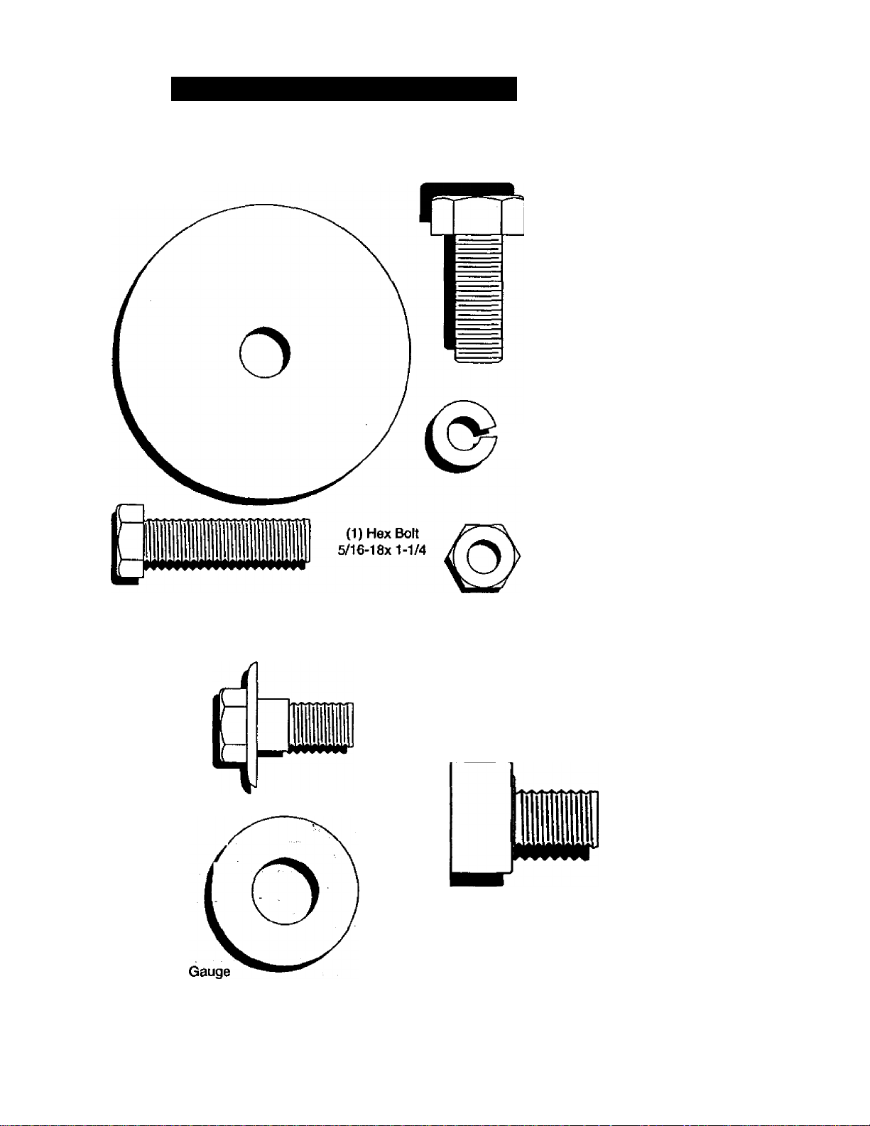
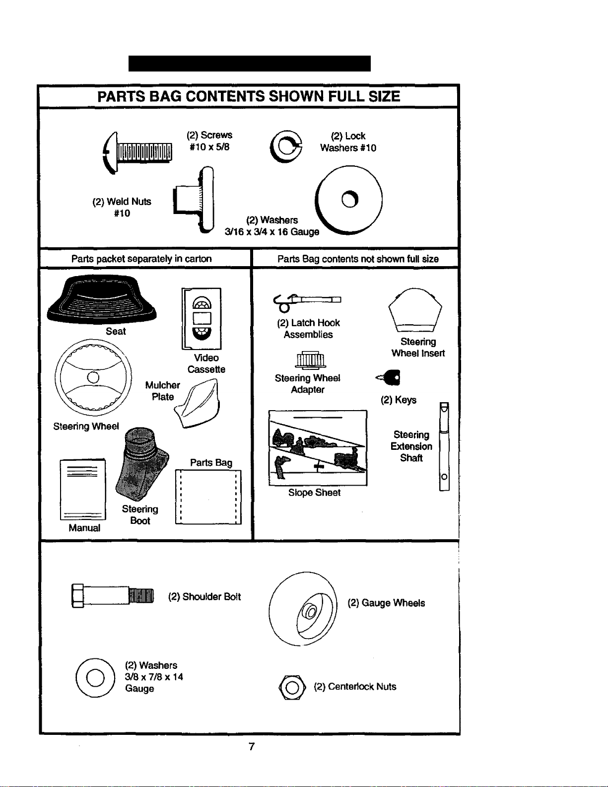
PARTS BAG CONTENTS SHOWN FULL SIZE
(1) Large Flat Washer
CONTENTS OF HARDWARE PACK
(1)HexBott
3/8-16x1
(1) Lockwasher
3/8
(1) Shoulder Bolt
5/16-18
(1) Washer
(1) Locknut
5/16-18
(1) Knob
Page 7
CONTENTS OF HARDWARE PACK
Page 8
ASSEMBLY
Your new tractor has been assembled at the factory with exception of those parts left
unassembled for shipping purposes. To ensure safe and proper operation of your tractor
all parts and hardware you assemble must be tightened securely. Use the correct tools
as necessary to insure proper tightness. Review the video cassette before you begin.
TOOLS REQUIRED FOR ASSEMBLY
A socket wrench set will make assembly
easier. Standard wrench sizes you need
are listed below.
(119/16“ wrench (1) 3/4" Socket w/
(2) 1/2" wrench dnve ratchet
(1) 3/4" wrench (1) Phillips Screwi1) Utility knife driver
(l)Pliers (1) Tire pressure
^auge
When right or left hand is mentioned in
this manual, it means, from your point of
view, when you are in the operating posi
tion (seated behind the steering wheel).
TO REMOVE TRACTOR FROM
CARTON
UNPACK CARTON
• Remove all accessible loose parts and
parts boxes from shipping carton (See
page 6).
• Cut, from top to bottom, along lines on
all four corners of shipping carton, and
lay panels flat.
• Check for any additional loose parts or
boxes and remove.
BEFORE ROLLING TRACTOR OFF SKID
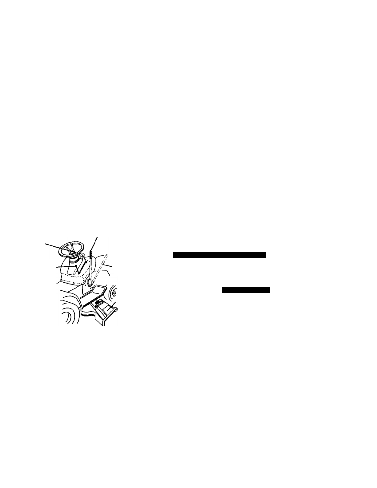
ATTACH STEERING WHEEL
ASSEMBLE EXTENSION SHAFT AND
BOOT
• Slide extension shaft onto lower steer
ing shaft. Align mounting holes in exten
sion and lower shafts and install 5/16
hex bolt and locknut. Tighten securely.
IMPORTANT: Tighten bolt and nut secure
ly to 18-22 ft. lbs. torcjue.
• Place tabs of steering boot over tab
slots in dash and push down to secure.
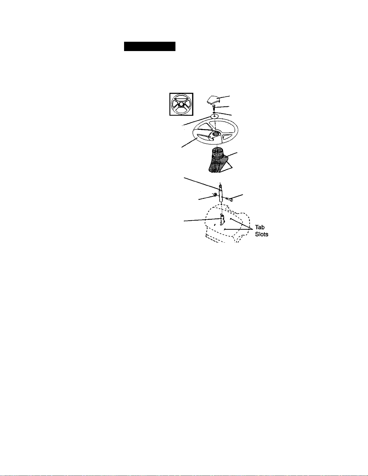
INSTALL STEERING WHEEL
• Position front wheels of the tractor so
they are pointing straight forward.
• Slide steering wheel adapter onto steer
ing shaft extension.
• Position steering wheel so cross bars
are horizontal (left to right) and slide
inside boot and onto adapter.
• Assemble large flat washer, 3/8 lock
washer, 3/8 hex bolt and tighten securely.
Insert
3/8 Hex Bolt
3/8 Lockwasher
Large Flat
Washer
Steering Wheel
Extension Shaft
5/16 Locknut
Lower
Steering
Shaft
Steering
Boot
Tabs
—- Adapter
5/16 Hex
Bolt
• Snap steering wheel insert into center
of steering wheel.
• Remove protective materials from trac
tor hood and grill.
IMPORTANT: Check for and remove any
staples in skid that may puncture tires
where tractor is to roll off skid.
TO ROLL TRACTOR OFF SKID (See
Operation section for location and
function of controls)
• Press lift lever plunger and raise attach
ment lift lever to its highest position.
• Release parking brake by depressing
clutch/brake pedal.
• Place freewheel control in freewheeling
position to disengage transmission (See
TO TRANSPOfir in the Operation
section of this manual).
• Roll tractor forward off skid.
• Remove banding holding discharge
guard up against tractor.
8
Page 9
HOW TO SET UP YOUR TRACTOR
CHECK BATTERY
• Lift seat pan to raised position and open
battery box door.
• If this battery is put into service after
month and year indicated on label (label
located between terminals) charge bat
tery for minimum of one hour at 6-10
amps. (See "BATTERY" in
MAINTENANCE section of this manual
for charging instructions). '
Seat Pan
Battery
Box Door
Terminal
Terminal
Label
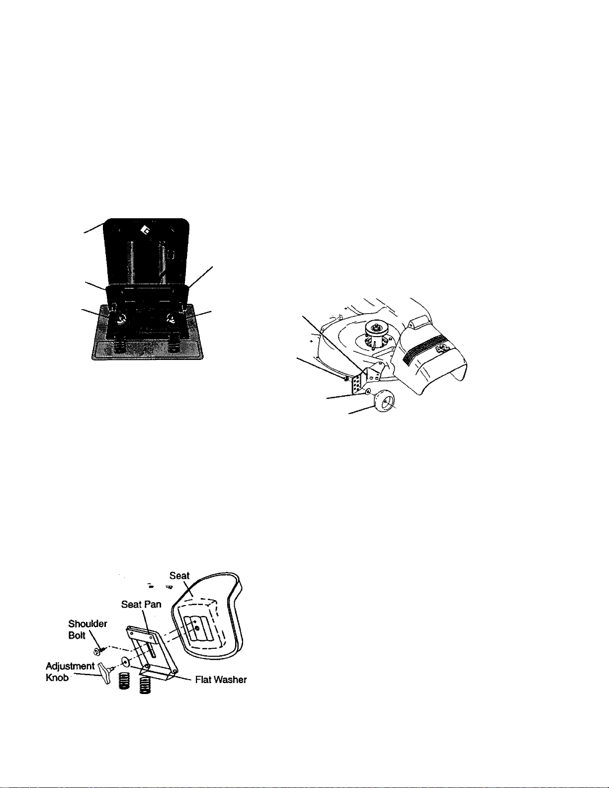
ASSEMBLE GAUGE WHEELS TO
MOWER DECK
The gauge wheels are designed to keep
the mower deck in proper position when
operating mower. Be sure they are proper
ly adjusted to ensure optimum mower per
formance.
• Assemble gauge wheels with tractor on
a flat level surface.
• Adjust mower to desired cutting height
(See TO ADJUST MOWER CUTTING
HEIGHT in the Operation section of this
manual).
• With mower in desired height of cut po
sition, gauge wheels should be assem
bled so they are slightly off the ground.
Install gauge wheel in appropriate hole
with shoulder bolt, 3/8 washer, and 3/8-
16 locknut and tighten securely.
• Repeat for opposite side installing
gauge wheel in same adjustment hole.
Gauge Wheel
Mounting
Bracket
INSTALL SEAT
Adjust seat before tightening adjustment
knob.
• Remove cardboard packing on seat pan.
• Place seat on seat pan and assemble
shoulder bolt. Tighten shoulder bolt
securely.
• Assemble adjustment knob and flat
washer loosely. Do not tighten.
• Lower seat into operating position and
sit on seat.
• Slide seat until a comfortable position is
reached which allows you to press
clutch/brake pedal all the way down.
• Get off seat without moving its adjusted
position.
• Raise seat and tighten adjustment knob
securely.
3/8-16
Locknut
3/8 Washer
Gauge Wheel
% Bolt
Shoulder
CHECK TIRE PRESSURE
The tires on your tractor were overinflated
at the factory for shipping purposes.
Correct tire pressure is important for best
cutting performance.
• Reduce tire pressure to PSI shown in
“PRODUCT SPECIFICATIONS" section
of this manual.
CHECK DECK LEVELNESS
For best cutting results, mower housing
should be properly leveled. See TO
LEVEL MOWER HOUSING” in the Service
and Adjustments section of this manual.
Page 10

CHECK FOR PROPER POSITION OF
ALL BELTS
See the figures that are shown for replac
ing motion and mower blade drive beits in
the Service and Adjustments sectoin of
this manuai. Verify that the beits are rout
ed correctiy.
CHECK BRAKE SYSTEM
After you learn how to operate your trac
tor, check to see that the brake is properiy
adjusted. See "TO ADJUST BRAKE” in
the Service and Adjustments section of
this manuai.
INSTALL MULCHER PLATE
• Instait two latch hooks to mulcher plate
using screw, washer, lock washer, and
weld nut as shown.
NOTE: Pre-assemble weld nut to latch
hook by inserting weld nut from the top
with hook pointing down.
• Tighten hardware securely.
• Raise and hold deflector shield in up
right position.
• Place front of mulcher plate over front of
mower deck opening and slide into
place, as shown.
• Hook front latch into hole on front of
mower deck.
• Hook rear latch into hole on back of
mower deck.
Deflector
Shield
Latch
Hooks
A.CAUTION: Do not remove discharge
guard from mower. Raise and hold guard
when attaching mulcher plate and allow it
to rest on plate while in operation.
TO CONVERT TO BAGGING OR
DISCHARGING
Simply remove mulcher plate and store in
a safe place. Your mower is now ready for
discharging or installation of optional
grass catcher accessory.
NOTE: It is not necessary to change
blades. The mulcher blades are designed
for discharging and bagging also.
i/CHECKUST
PLEASE REVIEW THE FOLLOWING
CHECKLIST:
✓ All assembly Instructions have been
completed.
✓ No remaining loose parts in carton.
✓ Battery is properly prepared and
charged. {Minimum 1 hour at 6 amps).
✓ Seat is adjusted comfortably and
tightened securely.
✓ All tires are properly inflated. (For
shipping purposes, the tires were
overinflated at the factory).
✓ Be sure mower deck is properly leveled
side-to-side/lront-to-rear for best
cutting results. {Tires must be properly
inflated for leveling).
✓ Check mower and drive belts. Be sure
they are routed properly around pulleys
and inside all belt keepers.
✓ Check wiring. See that all connections
are still secure and wires are properly
clamped.
✓ Before driving tractor, be sure free
wheel control is in drive position.
WHILE LEARNING HOW TO USE YOUR
TRACTOR, PAY EXTRA ATTENTION TO
THE FOLLOWING IMPORTANT ITEMS;
/ Engine oil is at proper level.
/ Fuel tank is filled with fresh, clean,
regular unleaded gasoline.
✓ Become familiar with ali controls - their
location and function. Operate them
before you start the engine.
✓ Be sure brake system is in safe operat
ing condition.
/ It is important to purge the transmis
sion before operating your tractor for
the first time. Follow proper starting
and transmission purging instructions
{See “TO START ENGINE” and
“PURGE TRANSMISSION” in the Op
eration section of this manual).
10
Page 11

OPERATION
These symbols may appear on your tractor or in literature supplied with the product.
Learn and understand their meaning.
3
O A
BATTERY
CAUTI(»i OR REVERSE FORWARD
WARNING
©
ENGINE ON
a i\i ^
FUEL
ENGINE OFF OIL PRESSURE LIGHTS ON OVER TEMP
CHOKE MOWER HEIGHT PARKING BRAKE UNLOCKED
? R N H L
ATTACHMENT REVERSE NEUTRAL HIGH
CLUTCH ENGAGED
i
LOCKED
LOW
4»
FAST
©I
LIGHT
SLOW
I.
I
MOWER LIFT
PARKING BRAKE
ATTACHMENT
IGNITION
DANGER, KEEP HANDS AND FEET AWAY
CLUTCH DISENGAGED
KEEP AREA CLEAR SLOPE HAZARDS
(SEE SAFETY RULES SECTION)
H“
T
FREE WHEEL
(Autontalic Models only)
11
Page 12
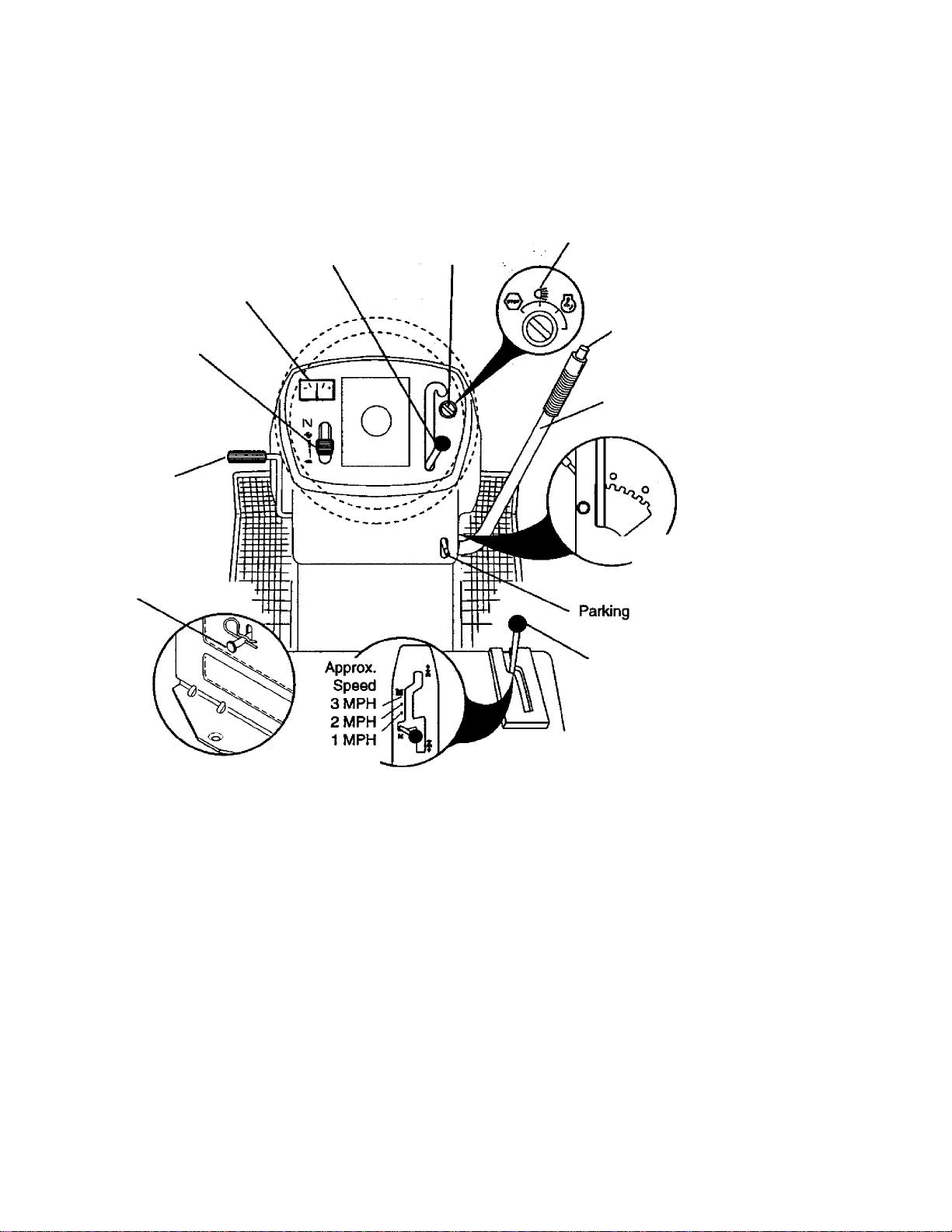
KNOW your TRACTOR
READ THIS OWNER'S MANUAL AND SAFETY RULES BEFORE OPERATING
YOUR TRACTOR
Compare the itlustrations with your tractor to familiarize yourself with the locations of
various controls and adjustments. Save this manual for future reference.
Light Switch
Position
Thrcttle/Choke
Control
Clutch/Brake
Control
Freewheel
Control
Ammeter
Attachment
Clutch Lever
Ignition
Switch
Lift Lever
Plunger
Attachment
Lift Lever
0 Height
Adjustment
Indicator
Our tractors conform to the safety standards of the American
National Standards Institute.
ATTACHMENT CLUTCH LEVER: Used to
engage the mower blades, or other attach
ments mounted to yourijrac^r.
LIGHT SWITCH: Turns the headlights on
and off.
THROTTLE/CHOKE CONTROL: Used to
control engine speed.
CLUTCH/BRAKE PEDAL: Used for
declutching and braking the tractor and
starting the engine.
FREEWHEEL CONTROL: Disengages
transmission for pushing or slowly towing
the tractor with the engine off.
Motion
Control Lever
MOTION CONTROL LEVER: Selects the
speed and direction of the tractor.
ATTACHMENT LIFT LEVER: Used to
raise and lower the mower deck or other
attachments mounted to your tractor.
LIFT LEVER PLUNGER: Used to release
attachment lift lever when changing its
position.
IGNITION SWITCH: Used for starting and
stopping the engine.
AMMETER: Indicates battery charging (+)
or discharging (-).
PARKING BRAKE: Locks clutch/brake
into the brake position.
12
Page 13

The operation of any tractor can result in foreign objects thrown into the
eyes, which can result in severe eye damage. Always wear safety glasses
or eye shields while operating your tractor or performing any adjustments or
repairs. We recommend a wide vision safety mask over spectacles, or stan
dard safety glasses.
_______________________________________
HOW TO USE YOUR TRACTOR
Your tractor is equipped with an operator
presence sensing switch. When engine Is
running, any attempt by the operator to
leave the seat without first setting the
parking brake will shut off the engine.
TO SET PARKING BRAKE
* Depress clutch/brake pedal into full
“BRAKE" position and hold.
• Place parking brake lever in “EN
GAGED” position and release pressure
from clutch/brake pedal. Pedal should
remain in “BRAKE” position. Make sure
parking brake will hold tractor secure.
Throttle/Choke
Control
“Brake”
Position
Ciutch/Brak(
Pedai “Drive’
Position
“Disengaged”
Position
STOPPING
MOWER BLADES -
• To stop mower blades, move attach
ment clutch lever to “DISENGAGED”
position. ^ ^
GROUND DRIVE -
• To stop ground drive, depress
clutch^rake pedal into full “BRAKE"
position.
• Move motion control lever to neutral (N)
position.
IMPORTANT: The motion control lever
does not return to neutral (N) position
when the clutch/brake pedal is depressed.
ENGINE-
• 'Move throttle control to slow position.
Attachment Clutch
Lever“Engaged”
Position
“Disengaged”
Position
Parking Brake
“Engaged”
Position
otion
Controi
Lever
_
NOTE: Failure to move throttle control to
slow position and allowing engine to idle
before stopping may cause engine to
“backfire”.
• Turn ignition key to “OFF position and
remove key. Always remove key when
leaving tractor to prevent unauthorized
use.
• Never use choke to stop engine.
IMPORTANT: Leaving the ignition switch
in any position other than “OFF will cause
the battery to be discharged, (dead).
NOTE: Under certain conditions when
tractor is standing idle with the engine run
ning, hot engine exhaust gases may
cause “browning” of grass. To eliminate
this possibility, always stop engine when
stopping tractor on grass areas.
^ CAUTION: Always stop tractor com
pletely, as described above, before leaving
the operator's position; to empty grass
catcher, etc.
THROTTLE CONTROL
Always operate engine at full throttle.
• Operating engine at less than full throt
tle reduces the battery charging rate.
• Full throttle offers the best bagging and
mower performance.
TO MOVE FORWARD AND BACKWARD
The direction and speed of movement is
controlled by the motion control lever.
• Start tractor with motion control lever in
neutral (N) position.
• Release parking brake and clutch/brake
pedal.
• Slowly move motion control lever to
desired position.
TO ADJUST MOWER CUTTING HEIGHT
The position of the attachment lift lever
determines the cutting height.
• Grasp lift lever.
• Press plunger with thumb and move
lever to desired position.
The cutting height range is approximately
1-1/2 to 4". The heights are measured
from the ground to the blade tip with the
engine not running. These heights are
approximate and may vary depending
upon soil conditions, height of grass and
types of grass being mowed.
13
Page 14
• The average lawn should be cut to
approximately 2-1/2 inches during the
cool season and to over 3 inches during
hot months. For healthier and better
looking lawns, mow often and after
moderate growth.
• For best cutting performance, grass
over 6 inches in height should be
mowed twice. Make the first cut relative
ly high; the second to desired height.
TO OPERATE MOWER
Your tractor is equipped with an operator
presence sensing switch. Any attempt by
the operator to leave the seat with the
engine running and the attachment clutch
engaged will shut off the engine.
• Select desired height of cut.
• Start mower blades by engaging attach
ment clutch control.
• TO STOP MOWER BLADES - disen
gage attachment clutch control.
i^CAUTION: Do not operate the mower
without either the entire grass catcher, on
mowers so equipped, or the discharge
guard in place.
Attachment Clutch
Lever "Engaged"
Position
Attachment Lift
Lever High Position
IMPORTANT: The motion control lever
does not return to neutral (N) position
when the clutch/brake pedal is depressed.
• To restart movement, slowly release
parking brake and clutch/brake pedal.
• Slowly move motion control lever to
slowest setting.
• Make all turns slowly.
TO TRANSPORT
When pushing or towing your tractor, be
sure to disengage transmission by placing
freewheel control in freewheeling position.
Freewheel control is located at the rear
drawbar of tractor.
• Raise attachment lift to highest position
with attachment lift control.
• Pull freewheel control knob out and hold
in position by inserting retainer spring
into fonvard hole of control rod.
• Do not push or tow tractor at more than
two (2) MPH.
• To reengage transmission, reverse
above procedure.
NOTE: To protect hood from damage when
transporting your tractor on a truck or a
trailer, be sure hood is closed and secured
to tractor. Use an appropriate means of
tying hood to tractor (rope, cord, etc.).
“DisengagecT
Position
Low
Position
Discharge
Guard
TO OPERATE ON HILLS
^CAUTION: Do not drive up or down
hilts witK slopes greater than 15° and do
not drive across any slope. Use the slope
guide provided at the badroHhis manual.
• Choose the slowest speed before start
ing up or down hills.
• Avoid stopping or changing speed on
hills.
• If slowing is necessary, move throttle
control lever to slower position,
• If stopping is absolutely necessary, push
clutch^rake pedal quickly to brake posi
tion and engage par1<ing brake.
• Move motion control lever to neutral (N)
position.
TOWING CARTS AND OTHER ATTACHMENTS
Tow only the attachments that are recom
mended by and comply with specifications
of the manufacturer of your tractor. Use
common sense when towing. Too heavy of
a load, while on a slope, is dangerous.
Tires can lose traction with the ground and
cause you to lose control of your tractor.
BEFORE STARTING THE ENGINE
CHECK ENGINE OIL LEVEL
• The engine in your tractor has been
shipped, from the factory, already filled
with summer weight oil.
• Check engine oil with tractor on level
ground.
14
Page 15

• Unthread and remove oil fill cap/dipstick; wipe oil off. Reinsert the dipstick
into the tube and rest oil fill cap on the
tube. Do not thread the cap onto the
tube. Remove and read oil level. If nec
essary, add oil until “FULL" mark on
dipstick is reached. Do not overfill.
• For cold weather operation you should
change oil for easier starting (See “OIL
VISCOSITY CHARr in the
Maintenance section of this manual).
• To change engine oil, see the
Maintenance section in this manual.
ADD GASOLINE
• Rll fuel tank. Use fresh, clean, regular
unleaded gasoline with a minimum of 87
octane. (Use of leaded gasoline will
increase carbon and lead oxide
deposits and reduce valve life). Do not
mix oil with gasoline. Purchase fuel in
quantities that can be used within 30
days to assure fuel freshness.
IMPORTANT: When operating in tempera
tures below 32“F(0°C), use fresh, clean
winter grade gasoline to help insure good
cold weather starting.
AwaRNING: Experience indicates that
alcohol blended fuels (called gasohol or
using ethanol or methanol) can attract
moisture which leads to separation and
formation of acids during storage. Acidic
gas can damage the fuel system of an
engine while in storage. To avoid engine
problems, the fuel system should be emp
tied before storage of 30 days or longer.
Drain the gas tank, start the engine and let
it run until the fuel lines and carburetor are
empty. Use fresh fuel next season. See
Storage Instructions for additional informa
tion. Never use engine or carburetor
cleaner products in the fuel tank or perma
nent damage may occur.
AcAUTION: Fill to bottom of gas tank
filler neck. Do not overfffl. Wipe off any
spilled oil or fuel. Do not store, spill or use
gasoline near an open flame.
TO START ENGINE
When starting the engine for the first time
or if the engine has run out of fuel, it will
take extra cranking time to move fuel from
the tank to the engine.
• Be sure freewheel control is in the
transmission engaged position.
• Sit on seat in operating position, depress
dutcfvbrake pedal and set parking bral«.
• Place motion control lever in neutral (N)
position.
• Move attachment clutch to “DISEN
GAGED” position.
• Move throttle control to choke position.
NOTE: Before starting, read the warm and
cold starting procedures below.
• Insert key into ignition and turn key
clockwise to “START” position and
release key as soon as engine starts.
Do not run starter continuously for more
than fifteen seconds per minute. If the
engine does not start after several
attempts, move throttle control to fast
position, wait a few minutes and try
again. If engine still does not start,
move the throttle control back to the
choke position and retry.
WARM WEATHER STARTING (50“ F and
above)
• When engine starts, move the throttle
control to the fast position.
• The attachments and ground drive can
now be used. If the engine does not
accept the load, restart the engine and
allow it to warm up for one minute using
the choke as described above.
COLD WEATHER STARTING ( 50“ F and
below)
• When engine starts, allow engine to run
with the throttle control in the choke
position until the engine runs roughly,
then move throttle control to fast posi
tion. This may require an engine warm
up period from several seconds to sev
eral minutes, depending on the temper
ature.
AUTOMATIC TRANSMISSION WARM UP
• Before driving the unit in cold weather,
the transmission should be warmed up
as follows:
• Be sure the tractor is on level ground.
• Place the motion control lever in neutral.
Release the parking brake and let the
clutch/brake slowly return to operating
position.
• Allow one minute for transmission to
warm up. This can be done during the
engine warm up period.
• The attachments can also be used dur
ing the engine warm-up period after the
transmission has been warmed up.
NOTE: At a high altitude (above 3000
feet) or in cold temperatures (below 32 F)
the carburetor fuel mixture may need to be
adjusted for best engine performance.
See “TO ADJUST CARBURETOR” in the
Service and Adjustments section of this
manual.
15
Page 16

PURGE TRANSMISSION
A CAUTION: Never engage or disen
gage freewheel lever while the engine is
running.
To ensure proper operation and perfor
mance, it is recommended that the trans
mission be purged before operating tractor
for the first time. This procedure will
remove any trapped air inside the trans
mission which may have developed during
shipping of your tractor.
IMPORTANT: Should your transmission
require removal for service or replace
ment, it should be purged after reinstalla
tion before operating the tractor.
• Place tractor safely on level surface wiüi
engine off and parking brake set.
• Disengage transmission by placing free
wheel control in freewheeling position
(See “TO TRANSPORT in this section
of manual).
• Sitting in the tractor seat, start engine.
After the engine is running, move throt
tle control to slow position. With motion
control lever in neutral (N) position,
slowly disengage clutch/brake pedal.
• Move motion control lever to full forward
position and hold for five (5) seconds.
Move lever to full reverse position and
hold for five (5) seconds. Repeat this
procedure three (3) times.
NOTE: During this procedure there will be
no movement of drive wheels. The air is
being removed from hydraulic drive sys
tem.
• Move motion control lever to neutral (N)
position. Shut off engine and set parking
brake.
• Engage transmission by placing free
wheel control in driving position (See
“TO TRANSPORT in this section of
manual).
• Sitting in the tractor seat^start engine.
After the engine is running, move throt
tle control to half (1/2) speed. With
motion control lever in neutral (N) posi
tion, slowly disengage clutch/brake
pedal.
• Slowly move motion control lever for
ward; after the tractor moves approxi
mately five (5) feet, slowly move motion
control lever to reverse position. After
the tractor moves approximately five (5)
feet return the motion control lever to
the neutral (N) position. Repeat this pro
cedure with the motion control lever
three (3) times.
• Your tractor is now purged and ready for
normal operation.
MOWING TIPS
• Tire chains cannot be used when the
mower housing is attached to tractor.
• Mower should be properly leveled for
best mowing performance. See TO
LEVEL MOWER HOUSING" in the
Service and Adjustments section of this
manual.
• The left hand side of mower should be
used for trimming.
• Drive so that clippings are discharged
onto the area that has been cut. Have
the cut area to the right of the tractor.
This will result in a more even distribu
tion of clippings and more uniform cut
ting.
• When mowing large areas, start by turn
ing to the right so that clippings will dis
charge away from shrubs, fences, drive
ways, etc. After one or two rounds, mow
in the opposite direction making left
hand turns until finished.
• if grass is extremely tall, it should be
mowed twice to reduce load and possi
ble fire hazard from dried clippings.
Make first cut relatively high; the second
to the desired height.
• Do not mow grass when it is wet. Wet
grass will plug mower and leave unde
sirable clumps. Allow grass to dry
before mowing.
• Always operate engine at full throttle
when mowing to assure better mowing
performance and proper discharge of
material. Regulate ground speed by se
lecting a low enough gear to give the
mower the best cutting performance as
well as the quality of cut desired.
• When operating attachments, select a
ground speed that will suit the terrain
and give best performance of the at
tachment being used.
16
Page 17

MULCHING MOWING TIPS
IMPORTANT: For best performance, keep
mower housing free of built-up grass and
trash. Clean after each use.
• The special mulching blade will recut
the grass clippings many times and
reduce them in size so that as they fall
onto the lawn they will disperse into the
grass and not be noticed. Also, the
mulched grass will biodegrade quickly
to provide nutrients for the lawn. Always
mulch with your highest engine (blade)
speed as this will provide the best recut
ting action of the blades.
• Avoid cutting your lawn when it is wet.
Wet grass tends to form clumps and
interferes with the mulching action. The
best time to mow your lawn is the early
afternoon. At this time the grass has
dried and the newly cut area will not be
exposed to the direct sun.
• For best results, adjust the mower cut
ting height so that the mower cuts off
only the top one-third of the grass
blades. For extremely heavy mulching,
reduce your width of cut on each pass
and mow slowly.
Certain types of grass and grass condi
tions may require that an area be
mulched a second time to completely
hide the clippings. When doing a sec
ond cut, mow across or perpendicular to
the first cut path.
Change your cutting pattern from week
to week. Mow north to south one week
then change to east to west the next
week. This will help prevent matting and
graining of the lawn.
Max 1/3
17
Page 18
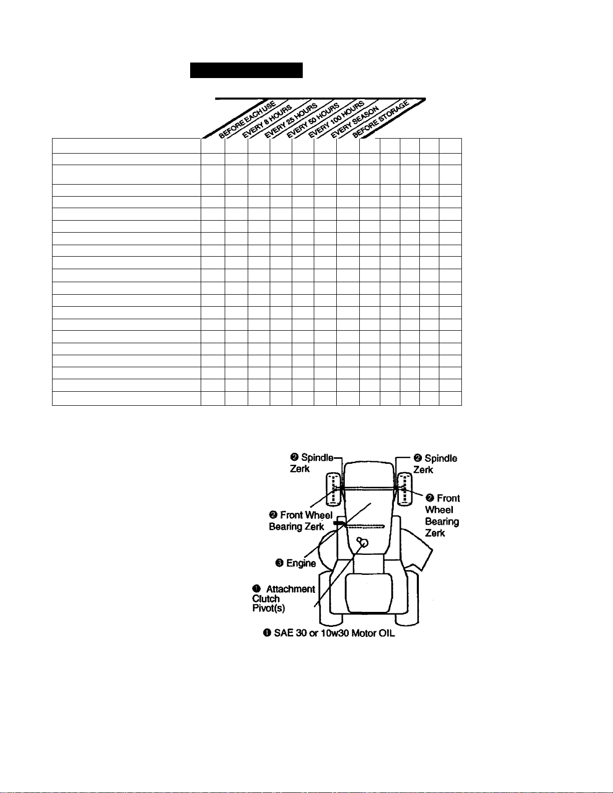
MAINTENANCE
CUSTOMER RESPONSIBILITIES
MAINTENANCE SCHEDULE
FILL IN DATES
AS YOU COMPLETE
REGULAR SERVICE
Check Brake Operation
Check Tire Pressure
Check Operator Presence and
Interlock Systems
Check for Loose Fasteners
Sharpen/Repiace Mower Blades
Lubricalion Chart
Check Battery Level
Clean Battery and Terminals
Check Transaxle Cooling
Adjust Blade Belt(s) Tension
Adjust Motion Drive Belt(s) Tension
Check Engine Oil Level
Change Ertgine Oil
Clean Air Rtter
Clean Air Screen
Inspect Muffler/Spark Arrester
Replace Oil Filter (If equipped)
Clean Engine Cooling Fins
Replace Spark Plug
Replace Mr Filter Paper Cartridge
Replace Fuel Filter
1 - Chang* mor* oft«n wfwn oparating undar a haavy load or in Ngh ambiant tamparaturaa.
2 - Sarvica mora oftan whan oparating in <^r1y or duaty oondHiona.
3 - If aquippad With ol Wtafp chang* avary SO houra.
4 - Raptoca bladaa mor* often whan mowing in sandy ad.
✓
✓
✓
✓
✓ ✓
✓
GENERAL RECOMMENDATIONS
The warranty on this tractor does not cover
items that have been subjected to operator
abuse or negligence. To receive fuii vaiue
from the warranty, operator must maintain
tractor as instructed in this manual. Some
adjustments will need to be made perìodicalty to properly maintain your tractor.
Alt adjustments in the Service and
Adjustments section of this manual should
be checked at least once each season.
• Once a year you should replace the
spark plug, clean or r^laSb air filter, and
check blades and belts for wear. A new
spark plug and clean air filter assure
proper air-fuel mixture and help your
engine run better and last longer.
BEFORE EACH USE
• Check engine oil level.
• Check brake operation.
• Check tire pressure.
• Check operator presence and interlock
systems for proper operation.
• Check for loose fasteners.
SERVICE DATES
✓ r ✓
✓ 4
✓ ✓
✓
✓
1^2.3
✓ 2
✓ 2
✓ s
✓
✓ 2
✓ ✓
✓ 2
S'tf aquippad wHh adhJatibla ayatem.
6 • Not raqutrad If aquippad wHh maintananca-fraa battary.
7 • Tlghlan front axM pf^ bolt to 35 ft.4bs. maximum.
✓
✓
✓
Do not ovartighton,
LUBRICATION CHART
® General Purpose Grease
O Refer to Maintenance “Engine” Section
IMPORTANT: Do not oil or grease the pivot
points which have special nylon bear-ings.
Viscous lubricants will attract dust and dirt
that will shorten the life of the self-lubricating
bearings. If you feel they must be lubricated,
use only a dry, powdered graphite type lubri
cant sparingly.
18
Page 19

TRACTOR
Always observe safety rules when per
forming any maintenance.
BRAKE OPERATION
If tractor requires more than six (6) feet
stopping distance at high speed in highest
gear, then brake must be adjusted. (See
“TO ADJUST BRAKP in the Service and
Adjustments section of this manual).
TIRES
• Maintain proper air pressure in ail tires
(See “PRODUCT SPECIFICATIONS"
section of this manual).
• Keep tires free of gasoline, oil, or insect
control chemicals which can harm rub
ber.
• Avoid stumps, stones, deep ruts, sharp
objects and other hazards that may
cause tire damage.
NOTE: To seal tire punctures and prevent
flat tires due to slow leaks, tire sealant
may be purchased from your local parts
dealer. Tire sealant also prevents tire dry
rot and corrosion.
OPERATOR PRESENCE SYSTEM
Be sure that operator presence and inter
lock systems are working properly. It your
tractor does not function as described
below, repair the problem immediately.
• The engine should not start unless the
clutch/brake pedal is fully depressed
and attachment clutch control is in the
disengaged position.
• When the engine is running, any
attempt by the operator to leave the
seat without first setting the parking
brake should shut off the engine.
• When the engine is running and the
attachment clutch is engaged, any
attempt by the operator to leave the
seat should shut off the engine.
• The attachment clutch should never
operate unless the operator is in the
seat.
BLADE CARE
For best results mower blades must be
kept sharp. Replace bent or damaged
blades.
BLADE REMOVAL
• Raise mower to highest position to allow
access to blades.
• Remove hex bolt, lock washer and flat
washer securing blade.
• Install new or resharpened blade with
trailing edge up towards deck as shown.
IMPORTANT: To ensure proper assembly,
center hole in blade must align with star
on mandrel assembly.
* Reassemble hex bolt, lock washer and
flat washer in exact order as shown.
• Tighten bolt securely (27-35 Ft. Lbs.
torque).
IMPORTANT: Blade bolt is grade 8 heat
treated.
Trailing Edge Up Mandrel Assembly
Flat Washer
Lock
Washer „
Blade
Star
' Hex Bolt
(Grade 8)*
TO SHARPEN BLADE
NOTE: We do not recommend sharpen
ing blade but if you do, be sure the blade
is balanced.
Care should be taken to keep the blade
balanced. An unbalanced blade will cause
excessive vibration and eventual damage
to mower and engine.
The blade can be sharpened with a file
or on a grinding wheel. Do not attempt
to sharpen while on the mower.
• To check blade balance, you will need a
5/8" diameter steel bolt, pin, or a cone
balancer. (When using a cone balancer,
follow the instmctions supplied with bal
ancer.)
NOTE: Do not use a nail for balancing
blade. The lobes of the center hole may
appear to be centered, but are not.
• Slide blade on to an unthreaded portion
of the steel bolt or pin and hold the bolt
or pin parallel with the ground. If blade
is balanced, it should remain in a hori
zontal position. If either end of the
blade moves downward, shaq>en the
heavy end until the blade is balanced.
BATTERY
Your tractor has a battery charging system
which is sufficient for normal use.
However, periodic charging of the battery
with an automotive charger will extend its
life.
• Keep battery and terminals clean.
• Keep battery bolts tight.
• Keep small vent holes open.
• Recharge at 6-10 amperes for 1 hour.
NOTE: The original equipment battery on
your tractor is maintenance free. Do not
.jgattempt to open or remove caps or covers.
Page 20

Adding or checking level of electrolyte is
not necessary.
TO CLEAN BATTERY AND TERMINALS
Corrosion and dirt on the battery and ter
minals can cause the battery to “leak”
power.
• Open battery box door.
• Disconnect BLACK battery cable first
then RED battery cable and remove
battery from tractor.
• Rinse the battery with plain water and
dry.
• Clean terminals and battery cable ends
with wire brush until bright.
• Coat terminals with grease or petroleum
jelly.
• Reinstall battery (See “REPLACING
BATTERY" in the SERVICE AND
ADJUSTMENTS section of this manu-
alL
V-BELTS
Check V-belts for deterioration and wear
after 100 hours of operation and replace if
necessary. The belts are not adjustable.
Replace belts if they begin to slip from
wear.
TRANSAXLE COOLING
The transmission fan and cooling fins
should be kept clean to assure proper
cooling.
Do not attempt to clean fan or transmis
sion while engine is running or while the
transmission is hot.
• Inspect cooling fan to be sure fan
blades are intact and clean.
• Inspect cooling fins for dirt, grass clip
pings and other materials. To prevent
damage to seals, do not use com
pressed air or high pressure sprayer to
clean cooling fins.
TRANSAXLE PUMP FLUID
The transaxle was sealed at the factory
and fluid maintenance is not required for
the life of the transaxle. Should the
transaxle ever leak or »qiwe sen/icing,
contact your nearest authorized service
center/department.
ENGINE
LUBRICATION
Only use high quality detergent oil rated
with API service classification SF, SG, or
S H. Select the oil’s SAE viscosity grade
according to your expected operating tem
perature. *
Change the oil after every 50 hours of
operation or at least once a year if the
tractor is not used for 50 hours in one
year.
Check the crankcase oil level before start
ing the engine and after each eight (8)
hours of operation. Tighten oil fil! cap/dip-
stick securely each time you check the oil
level.
TO CHANGE ENGINE OÍL
Determine temperature range expected
before oil change. All oil must meet API
sen/ice classification SF, SG, or SH.
• Be sure tractor is on level surface.
• Oil will drain more freely when warm.
• Catch oil in a suit£üt>le container.
• Remove oil fill cap/dipstick. Be careful
not to allow dirt to enter the engine
when changing oil.
• Remove drain plug.
• After oil has drained completely, replace
oil drain plug and tighten securely.
• Refill engine with oil through oil fill dip
stick tube. Pour slowly. Do not overfill.
For approximate capacity see “PROD
UCT SPECIFICATIONS" section of this
manual.
• Use gauge on oil fill cap/dipstick for
checking level. Insert dipstick into the
tube and rest the oil fill cap on the tube.
Do not thread the cap onto the tube
when taking reading. Keep oil at
“FULL" line on dipstick. Tighten cap
onto the tube securely when finished.
Air Cleaner
Cover
Foam
Pre-Cleaner
Air
Cleaner
Paper
Cartridge
Oil Drain
Plug
Oil Fill
20
Cover Knob
Wing
Nut
Rubber
Gromme!
Air Cleaner
Base
CapOipstick
Page 21

CLEAN AIR SCREEN
Air screen must be kept free of dirt and
chaff to prevent engine damage from over
heating. Clean with a wire brush or com
pressed air to remove dirt and stubborn
dried gum fibers.
AIR FILTER
Your engine will not run properly using a
dirty air filter. Clean the foam pre-cleaner
after every 25 hours of operation or every
season. Service paper cartridge every
100 hours of operation or every season,
whichever occurs first.
Service air cleaner more often under dusty
conditions.
• Remove knob and cover.
• Remove wing nut and air cleaner from
base.
TO SERVICE PRE-CLEANER
• Slide foam pre-cleaner off cartridge.
• Wash it in liquid detergent and water.
• Squeeze it dry in a clean cloth. Allow it
to dry.
• Saturate it in engine oil. Wrap it in
clean, absorbent cloth and squeeze to
remove excess oil.
TO SERVICE CARTRIDGE
• Replace a dirty, bent, or damaged car
tridge.
NOTE: Do not wash the paper cartridge
or use pressurized air, as this will damage
the cartridge.
• Reinstall the pre-cleaner (cleaned and
oiled) over the paper cartridge.
• Reassemble air cleaner, wing nut, cover
and tighten knob securely.
CLEAN AIR INTAKE/COOLING AREAS
To insure proper cooling, make sure the
grass screen, cooling fins, and other
external surfaces of the engine are kept
clean at all times.
Every 100 hours of operation (more often
under extremely dustyydi^ conditions),
remove the blower housing and other
cooling shrouds. Clean the cooling fins
and external surfaces as necessary. Make
sure the cooling shrouds are reinstalled.
NOTE: Operating the engine with a
blocked grass screen, dirty or plugged
cooling fins, and/or cooling shrouds re
moved will cause engine damage due to
overheating.
MUFFLER
Inspect and replace corroded muffler and
spark arrester (if equipped) as it could cre
ate a fire hazard and/or damage.
SPARK PLUGS
Replace spark plugs at the beginning of
each mowing season or after every 100
hours of operation, whichever occurs first.
Spari< plug type and gap setting are
shown in “PRODUCT SPECIFICATIONS”
section of this manual.
ENGINE OIL FILTER
Replace the engine oil filter every season
or every other oil change if the tractor is
used more than 100 hours in one year.
• Drain oil from engine crankcase (See
TO CHANGE ENGINE OIL" in this sec
tion of this manual, through step remove
drain plug).
• Remove oil filter and wipe off filter
adapter.
• Apply a thin coating of new engine oil to
the rubber gasket on replacement oil fil
ter.
• Install replacement oil filter on filter
adapter. Turn oil filter clockwise until
rubber gasket contacts the filter adapter,
then tighten filter an additional 1/2 turn.
• Fill crankcase with new oil (See TO
CHANGE ENGINE OIL” in this section
of this manual). For approximate capac
ity see “PRODUCT SPECIFICATIONS”
section of this manual.
• Start the engine and check for oil leaks.
Correct any leaks before placing engine
into full operation.
Oil Filter
IN-LINE FUEL FILTER
The fuel fitter should be replaced once
each season. If fuel filter becomes
clogged, obstructing fuel flow to carbure
tor, replacement is required.
• With engine cool, remove filter and plug
fuel line sections.
21
Page 22

• Place new fuel filter In position in fuel
line with arrow pointing towards carbu
retor.
• Be sure there are no fuel line leaks and
clamps are properly positioned.
• Immediately wipe up any spilled gaso
line.
CLEANING
• Clean engine, battery, seat, finish, etc.
of all foreign matter.
• Keep finished surfaces and wheels free
of all gasoline, oil, etc.
• Protect painted surfaces with automo
tive type wax.
We do not recommend using a garden
hose to clean your tractor unless the elec
trical system, muffler, air filter and carbure
tor are covered to keep water out. Water
in engine can result in a shortened engine
life.
SERVICE AND ADJUSTIVIENTS
.^CAUTION: Before perfonming any service or adjustments:
• Depress clutch/brake pedal fully and set parking brake.
• Place motion control lever in neutral (N) position.
• Place attachment clutch in “DISENGAGED” position.
• Turn ignition key “OFP and remove key.
• Make sure the blades and all moving parts have completely stopped.
• Disconnect spark plug wire from spark plug and place wire where it cannot come in
contact with plug.
________________________________________________________
TRACTOR
TO REMOVE MOWER
Mower will be easier to remove from the
light side of tractor.
• Place attachment clutch in “DISEN
GAGED” position.
• Move attachment lift lever forward to
lower mower to its lowest position.
• Roll belt off engine pulley.
• Disconnect clutch rod from clutch lever
by removing retainer spring.
• Disconnect anti-swaybar from chassis
bracket by removing retainer spring.
• Disconnect suspension arms from rear
deck brackets by removing retainer
springs.
_ Clutch Lever-
Clutch Rod
Suspension *
Arms
• Disconnect front links from deck by
removing retainer springs.
• Raise lift lever to raise suspension
arms. Slide mower out from under trac
tor.
IMPORTANT: If an attachment other than
the mower deck is to be mounted on the
tractor, remove the front links.
TO INSTALL MOWER
• Raise attachment lift lever to its highest
position.
• Slide mower under tractor with dis
charge guard to right side of tractor.
• Lower lift lever to its lowest position.
• Install mower in reverse order of
removal instructions.
Retainer
Spring
Engine Pulley
Front
Link
Retainer
Spring
Retainer Springs
{Both Sides)
Retainer Springs
(Both Sides)
Anti-Swaybar
Page 23

TO LEVEL MOWER HOUSING
Adjust the mower while tractor is parked
on level ground or driveway. Make sure
tires are properly inflated (See "PROD
UCT SPECIFICATIONS”). If tires are
over or underinflated, you will not properly
adjust your mower.
SIDE-TO-SIDE ADJUSTMENT
• Raise mower to its highest position.
• At the midpoint of both sides of mower,
measure height from bottom edge of
mower to ground. Distance “A” on both
sides of mower should be the same or
within 1/4" of each other.
• If adjustment is necessary, make adjust
ment on one side of mower only.
• To raise one side of mower, tighten lift
link adjustment nut on that side.
• To lower one side of mower, loosen lift
link adjustment nut on that side.
NOTE: Each full turn of adjustment nut
will change mower height about 1/8".
• Recheck measurements after adjusting.
Bottom edge of Bottom edge
• Before making any necessary adjust
ments, check №at both front links are
equal in length. Both links should be
approximately 10-3/8".
• If links are not equal in length, adjust
one link to same length as o№er link.
• To lower front of mower loosen nut “E”
on both front links an equal number of
turns.
• When distance “D” is 1/8" to 1/2" lower
at front than rear, tighten nuts “P
against trunnion on both front links.
• To raise front of mower, loosen nut “P
from trunnion on both front links.
Tighten nut "P on both front links an
equal number of turns.
• When distance “D” is 1/8" to 1/2" lower
at front than rear, tighten nut “P against
trunnion on both front links.
• Recheck side-to-side adjustment.
Mandrel
* •
FRONT-TO-BACK ADJUSTMENT
IMPORTANT: Deck must be level side-to-
side. If the following front-to-back adjust
ment is necessary, be ^re»to adjust both
front links equally so mower will stay
level side-to-side.
To obtain the best cutting results, the
mower housing should be adjusted so that
the front is approximately 1/8" to 1/2"
lower than the rear when the mower Is in
its highest position.
Check adjustment on right side of tractor.
Measure distance “D” directly in front and
behind the mandrel at bottom edge of
mower housing as shown.
Both Front Links Should be Equal in Length
Nut
Tmnnion
Front Links
TO REPLACE MOWER BLADE DRIVE
BELT (See Illustration Next Page)
The mower blade drive belt may be
replaced without tools. Park the tractor on
level surface. Engage parking brake.
BELT REMOVAL-
• Remove mower from tractor (See “TO
REMOVE MOWER” in this section of
this manual).
• Work belt off both mandrel pulleys and
idler pulleys.
• Pull belt away from mower.
23
Page 24

BELT INSTALLATION -
• Install new belt In reverse order of
removal.
• Make sure belt is |n all pulley grooves
and inside all belt guides.
• Install mower in reverse order of
removal instructions.
Mandrel
Pulley
Mandrel
Pulley
TO ADJUST BRAKE
Your tractor is equipped with an adjustable
brake system which is mounted on the
side of the transaxle.
If tractor requires more than six (6) feet
stopping distance at high speed in high
est gear, then brake must be adjusted.
• Depress clutchAirake pedal and engage
parking brake.
• Measure distance between brake oper
ating arm and nut “A” on brake rod.
• If distance is other than 1-9/16", loosen
jam nut and turn nut “A” until distance
becomes 1-9/16". Retighten jam nut
against nut “A".
• Road test tractor for proper stopping
distance as stated above. Readjust if
necessary. If stopping distance is still
greater than six (6) feet in highest gear,
further maintenance is necessary.
Contact your nearest authorized ser
vice center/department.
Idler
Pulleys
TO REPLACE MOTION DRIVE BELT
Park the tractor on level surface. Engage
parking brake. For assistance, there is a
belt installation guide decal on bottom side
of left footrest.
• Remove mower (See “TO REMOVE
MOWER” in this section of this manual.)
• Remove belt from stationary idler and
clutching idler.
• Pull belt slack toward rear of tractor.
Carefully remove belt upwards from
transmission input pulley and over cool
ing fan blades.
• Pull belt toward front of tractor and
remove downward from around engine
pulley.
• Install new belt by reversing above pro
cedure.
Jam Nut
Nut “A”
Operating
Arm
Do Not touch this nut. If further brake adjustment is
necessary contact your nearest authorized service
center/department 24
Page 25

TO ADJUST MOTION CONTROL LEVER
The motion control lever has been preset
at the factory and adjustment should not
be necessary.
If for any reason the motion control lever
will not hold its position while at a selected
speed, it may be adjusted at the friction
pack located on the right side of transmis
sion.
• Park tractor on level surface. Stop trac
tor by turning ignition key ta“OFP posi
tion, and engage parking brake.
• Adjust motion control lever by tightening
adjustment locknut one half (1/2) turn.
NOTE; If for any reason the effort to move
the motion control lever becomes too
excessive, reverse the above adjustment
procedure by loosening locknut 1/4 to 1/2
turn.
Road test tractor after adjustment and
repeat procedure if necessary.
TRANSMISSION REMOVAL/REPLACE-
MENT
Should your transmission require removal
for service or replacement, it should be
purged after reinstallation and before
operating the tractor. See “PURGE
TRANSMISSION" in the Operation section
of this manual.
Adjustment
Locknut
TO ADJUST STEERING WHEEL ALIGN
MENT
If steering wheel crossbars are not hori
zontal (left to right) when y^eels are posi
tioned straight forwardrrernove steering
wheel and reassemble per instructions in
the Assembly section of this manual.
FRONT WHEEL TOE-IN/CAMBER
The front wheel toe-in and camber are not
adjustable on your tractor. If damage has
occurred to affect the front wheel toe-in or
camber, contact your nearest authorized
service center/department.
TO REMOVE WHEEL FOR REPAIRS
• Block up axle securely.
• Remove axle cover, retaining ring and
washers to allow wheel removal (rear
wheel contains a square key • Do not
lose).
• Repair tire and reassemble.
• On rear wheels only: align grooves in
rear wheel hub and axle. Insert square
key.
• Replace washers and snap retaining
ring securely in axle groove.
• Replace axle cover.
NOTE: To seal tire punctures and prevent
flat tires due to slow leaks, tire sealant
may be purchased from your local parts
dealer. Tire sealant also prevents tire dry
rot and corrosion.
Washers
Retaining
Ring
/^xle Cover Square Key
(Rear Wheei Only)
TO START ENGINE WITH A WEAK
BATTERY
ACAUTION; Lead-acid batteries gener
ate explosive gases. Keep sparks, flame
and smoking materials away from batter
ies. Always wear eye protection when
around batteries.
If your battery is too weak to start the
engine, it should be recharged. (See
"BATTERY* in the MAINTENANCE sec
tion of this manual).
If “jumper cables” are used for emergency
starting, follow this procedure;
IMPORTANT: Your tractor Is equipped
with a 12 volt negative grounded system.
The other vehicle must also be a 12 volt
negative grounded system. Do not use
your tractor battery to start other vehicles.
TO ATTACH JUMPER CABLES -
• Connect each end of the RED cable to
the POSITIVE (+) terminal of each bat
tery, taking care not to short against
chassis.
• Connect one end of the BLACK cable to
the NEGATIVE (-) terminal of fully
charged battery.
• Connect the other end of the BLACK
cable to good CHASSIS GROUND,
away from fuel tank and battery.
25
Page 26

TO REMOVE CABLES, REVERSE
ORDER -
• BLACK cable first from chassis and
then from the fully charged battery.
• RED cable last from both batteries.
Positive Terminal Negative Terminai
Chassis
Posile terminal
^ Cables
Charged Battery
Negative Terminal
REPLACING BATTERY
ACAUTION: Do not short battery termi
nals by allowing a wrench or any other
object to contact both terminals at the
same time. Before connecting battery,
remove metal bracelets, wristwatch
bands,rings,etc.
Positive terminal must be connected first
to prevent sparking from accidental
grounding.
• Lift seat pan to raised position and open
battery box door.
• Disconnect BLACK battery cable first
then RED battery cable and carefully
remove battery from tractor.
• Install new battery with terminals in
same position as old battery.
• First connect RED battery cable to posi
tive (+) terminal with hex bolt and keps
nut as shown. Tighten securely.
• Connect BLACK grounding cable to
negative (-) terminal with remaining hex
bolt and k^s nut. Tighten securely.
• Close battery box door.
Seat Pan
Battery
Box Door
Keps
Nut‘~'^^ Hex Bolt
PositiveiRed) Cable Negative (Black)
Cable
TO REPLACE HEADLIGHT BULB
• Raise hood.
• Pull bulb holder out of the hole in the
backside of the grill.
• Replace bulb in holder and push bulb
holder securely back into the hole in the
backside of the grill.
• Close hood.
INTERLOCKS AND RELAYS
Loose or damaged wiring may cause your
tractor to run poorly, stop running, or pre
vent it from starting.
• Check wiring. See electrical wiring dia
gram in the Repair Parts section.
TO REPLACE FUSE
Replace with 30 amp automotive-type
plug-in fuse. The fuse holder is located
behirKi the dash.
TO REMOVE HOOD AND GRILL AS
SEMBLY
• Raise hood.
• Linsnap headlight wire connector.
• Stand in front of tractor. Grasp hood at
sides, tilt toward engine and lift off of
tractor.
• To replace, reverse above procedures.
ENGINE
Maintenance, repair, or replacement of the
emission control devices and s^tems,
which are being done at the customers
expense, may be performed by any non
road engine repair establishment or indi
vidual. Warranty repairs must be per
formed by an authorized engine manufac
turer's service outlet.
TO ADJUST THROTTLE CONTROL
CABLE
The throttle control has been preset at the
factory and adjustment should not be nec
essary. Check adjustment as described
below before loosening cable. If adjust
ment is necessary, proceed as follows:
• With engine not running, move throttle
26
Page 27

control lever from slow to choke posi
tion. Slowly move lever from choke to
fast position.
• Check to see if hole in throttle lever and
hole in speed control bracket are ,
aligned.
• If holes are not aligned, loosen cable
clamp screw and align the holes by
inserting a pencil or a 1/4" drill bit
through both holes.
• Pull throttle cable up to remove slack
and tighten cable clamp screw. Remove
alignment pencil or drill bit.
TO ADJUST CARBURETOR
The carburetor has been preset at the fac
tory and adjustment should not be neces
sary. However, minor adjustment may be
required to compensate for differences in
fuei, temperature, altitude or load. If the
carburetor does need adjustment, proceed
as follows:
In general, turning the adjusting needles
in (clockwise) decreases the supply of fuel
to the engine giving a leaner fuel/atr mix
ture. Turning the adjusting needles out
(counterclockwise) increases the supply of
fuel to the engine giving a richer fuel/air
mixture.
IMPORTANT: Damage to the needles and
the seats in carburetor may result if nee
dle is turned in too tight.
NOTE: The carburetor on this engine is
low emission. It is equipped with an idle
fuei adjusting needle with a limiter cap,
which allows some adjustment within the
limits allowed by the cap. Do not attempt
to remove the limiter cap. The limiter cap
cannot be removed without breaking the
adjusting needle.
• Be sure you have a clean air filter and
the throttle control cable is adjusted
properly (see above).
• Start engine and allow to warm for five
minutes. Make adjus^errts with engine
running and shift/motion controi lever in
neutral (N) position.
• Idle speed setting - With throttle control
lever in slow position, engine should
idle at 1750 RPM. If engine idles too
slow or fast, turn idle speed adjusting
screw in or out until correct idle is at
tained.
• Idie fuel needle setting - With throttle
contrd lever in slow position, turn idle
fuel adjusUnent needle in (clockwise)
until engine begins to die and then turn
out (counterclockwise) until engine runs
rough. Turn needle to a point midway
between those two positions.
• Recheck idle speed. Readjust if neces
sary.
ACCELERATION TEST-
• Move throttle control lever from slow to
fast position. If engine hesitates or dies,
turn idle fuel adjusting needle out
(counterclockwise) 1/8 turn. Repeat test
and continue to adjust, if necessary,
until engine accelerates smoothly.
High speed stop is factory adjusted. Do
not adjust - damage may result.
IMPORTANT: Never tamper with the
engine governor, which is factory set for
proper engine speed. Overspeeding the
engine above the factory high speed set
ting can be dangerous. If you think the
engine-governed high speed needs
adjusting, contact your nearest AUTHO
RIZED service center/department, which
has proper equipment and experience to
make any necessary adjustments.
Cable Clamp
Screw
Speed control
Bracket
Throttle Lever
Idle Speed
Adjusting
Screw
Idle Fuel
Adjusting Needle
------------
27
Page 28

STORAGE
Immediately prepare your tractor for stor
age at the end of the season or if the trac
tor will not be used for 30 days or more.
A.CAUTION: Never store the tractor with
gasoline in the tank inside a building
where fumes may reach an open flame or
spark. Allow the engine to cool before stor
ing in any enclosure.
TRACTOR
Remove mower from tractor for winter
storage. This will allow you to clean it thor
oughly. Remove all dirt, grease, leaves,
etc. Store in a clean, diy area.
• Clean entire tractor (See “CLEANING” in
the Maintenance section of this manual).
• Inspect and replace belts, if necessary
(See belt replacement instructions in the
Service and Adjustments section of this
manual).
• Lubricate as shown in the Maintenance
section of this manual.
• Be sure that all nuts, bolts and screws
are securely fastened. Inspect moving
parts for damage, breakage and wear.
Replace if necessary.
• Touch up all rusted or chipped paint sur
faces; sand lightly before painting.
BATTERY
• Fully charge the battery for storage.
• After a period of time in storage, battery
may require recharging.
• To help prevent corrosion and power
leakage during long periods of storage,
battery cables should be disconnected
and battery cleaned thoroughly (see “TO
CLEAN BATTERY AND TERMINALS" in
the Maintenance section of this manual).
• After cleaning, leave cables disconnect
ed and place cables where they cannot
come in contact with battery terminals.
• If battery is removed from tractor for
storage, do not store battery directly on
concrete or damp surfaces.
ENGINE '
FUEL SYSTEM
IMPORTANT: It is important to prevent
gum deposits from forming in essential fuel
system parts such as carburetor, fuel filter,
fuel hose, or tank during storage. Also,
experience indicates that alcohol blended
fuels (called gasohol or using ethanol or
methanol) can attract moisture which leads
to separation and formation of acids during
storage. Acidic gas can damage the fuel
system'of an engine while in storage.
• Drain the fuel tank.
• Start the engine and let it run until the
fuel lines and carburetor are empty.
• Never use engine or carburetor cleaner
products in the fuel tank or permanent
damage may occur.
• Use fresh fuel next season.
NOTE: Fuel stabilizer is an acceptable
alternative in minimizing the formation of
fuel gum deposits during storage. Add sta
bilizer to gasoline in fuel tank or storage
container. Always follow the mix ratio
found on stabilizer container. Run engine
at least 10 minutes after adding stabilizer
to allow the stabilizer to reach the carbure
tor. Do not drain the gas tank and carbure
tor if using fuel stabilizer.
ENGINE OIL
Drain oil (with engine warm) and replace
with clean engine oil. (See “ENGINE" in
the Maintenance section of this manual).
CYLINDER(S)
• Remove Spark piug(s).
• Pour one ounce of oil through spark plug
hole(s) into cylinder(s).
• Turn ignition key to “START" position for
a few seconds to distribute oil.
• Replace with new spark plug(s).
OTHER
• Do not store gasoline from one season
to another.
• Replace your gasoline can if it starts to
rust. Rust and/or dirt in your gasoline will
cause problems.
• If possible, store your tractor indoors
and cover it to give protection from dust
and dirt.
• Cover your tractor with a suitable protec
tive cover that does not retain moisture.
Do not use plastic. Plastic cannot
breathe, which allows condensation to
form and cause your tractor to rust.
IMPORTANT: Never cover tractor while
engine and exhaust areas are still warm.
28
Page 29

TROUBLESHOOTING CHART
PROBLEM
Will not start
Hard to start • Dirty air filter. • Clean/replace air filter.
CAUSE
• Out of fuel.
• Engine not “CHOKED”
properly.
• Engine flooded. • Wait several minutes before
• Bad spark plug.
• Dirty air filter.
• Dirtyiuel filter.
• Water in fuel.
• Loose or damaged wiring. • Check all wiring.
• Carburetor out of adjust
ment.
• Engine valves out of
adjustment.
• Bad spark plug. • Replace spark plug.
* Weak or dead battery.
• Dirty fuel filter. * Replace fuel filter.
• Stale or dirty fuel. • Drain fuel tank and refill with
• Loose or damaged wiring. • Check all wiring.
• Carburetor out of adjust
ment.
• Engine valves out of
adjustment.
CORRECTION
• Fill fuel tank.
• See TO START ENGINE” in
Operation section.
attempting to start.
• Replace spark plug.
• Ctean/replace air filter.
• Replace fuel filter.
• Drain fuel tank and carbure
tor, refill tank with fresh
gasoline and replace fuel fil
ter.
• See To Adjust Carburetor”
in Service and Adjustments
section.
• Contact an authorized ser
vice center.
• Recharge or replace battery.
fresh gasoline.
• See To Adjust Carburetor"
in Senrice and Adjustments
section.
• Contact an authorized ser
vice center.
Engine will not turn
over
• Clutch/brake pedal not
depressed.
• Attachment clutch is
engaged.
• Weak or dead battery.
• Blown fuse.
• Corroded battery terminSls.
• Loose or damaged wiring. • Check all wiring.
• Faulty ignition switch.
• Faulty solenoid or starter.
• Faulty operator presence
switch(es).
29
• Depress clutch/brake pedal.
• Disengage attachment
clutch.
• Recharge or replace battery.
• Replace fuse.
• Clean battery terminals.
• Check/replace ignition
switch.
• Check/replace solenoid or
starter.
• Contact an authorized ser
vice center.
Page 30

TROUBLESHOOTING CHART
PROBLEM
CAUSE
CORRECTION
Engine clicks but
will not start
Loss of power
• Weak or dead battery.
• Corroded battery termi
nals.
• Loose or damaged wiring. • Check alt wiring.
• Faulty solenoid or starter.
• Cutting too much
grass/too fast.
• Throttle in “CHOKP posi
tion.
• Build-up of grass, leaves
and trash under mower.
• Dirty air filter. • Ctean/replace air filter.
• Low oil level/dirty oil. • Check oil levei/change oil.
• Faulty spark plug. • Clean and regap or change
• Dirty fuel filter.
• Stale or dirty fuel. • Drain fuel tank and refill with
• Water in fuel. • Drain fuel tank and carbure
• Spark plug wire loose.
• Dirty engine air
screen/fins.
• Dirty/clogged muffler. • Clean/replace muffler.
• Loose or damaged wiring. • Check all wiring.
• Carburetor out of adjust
ment.
• Engine valves out of
adjustment.
• Recharge or replace battery.
• Clean battery terminals.
• Check/replace solenoid or
starter.
• Set in “Higher Cur position/reduce speed.
• Adjust throttle control.
• Clean underside of mower
housing.
spark plug.
• Replace fuel filter.
fresh gasoline.
tor, refill tank with fresh gaso
line and replace fuel filter.
• Connect and tighten spark
plug wire.
• Clean engine air screen/fins.
♦ See “To Adjust Carburetor" in
Service and Adjustments
section.
• Contact an authorized ser
vice center.
Excessive vibration • Worn, bent or loose blade. • Replace blade. Tighten blade
bolt.
• Bent blade mandrel. • Replace blade mandrel.
• Loose/damaged part(s). • Tighten loose part(s).
Replace damaged parts.
m- ^
Engine continues to
run when operator
leaves seat with at
tachment clutch
engaged
• Faulty operator-safety • Check wiring, switches and
presence control system. connections. If not
corrected, contact an autho
rized service center/
department.
30
Page 31

TROUBLESHOOTING CHART
PROBLEM
CAUSE
CORRECTION
Poor cut - uneven
Mower blades will
not rotate
Poor grass dis • Engine speed too slow.
charge
• Worn, bent or loose blade. • Replace blade. Tighten blade
• Mower deck not level.
• Buildup of grass, leaves,
and trash under mower.
• Bent blade mandrel.
• Clogged mower deck vent
holes from buildup of
grass, leaves, and trash
around mandrels.
• Obstruction in clutch • Remove obstruction.
mechanism.
• Worn/damaged mower
drive belt.
• Frozen idler pulley.
• Frozen blade mandrel. • Replace blade mandrel.
• Travel speed too fast.
* Wet grass. • Allow grass to dry before
• Mower deck not level.
• Low/uneven tire air pressure. pressure.
• Worn, bent or loose blade. • Replace/sharpen blade.
• Buildup of grass, leaves
and trash under mower. housing.
• Mower drive belt worn. • Replace mower drive belt.
• Blades improperly • Reinstall blades sharp edge
installed. down.
• Improper blades used.
• Clogged mower deck vent • Clean around mandrels to
holes from buildup of
grass, leaves, and trash
around mandrels.
bolt.
• Level mower deck.
• Clean underside of mower
housing.
• Replace blade mandrel.
• Clean around mandrels to
open vent holes.
• Replace mower drive belt.
• Replace idler pulley.
• Place throttle control in
“FAST position.
• Shift to slower speed.
mowing.
• Level mower deck.
• Check tires for proper air
Tighten blade bolt.
• Clean underside of mower
• Replace with blades listed in
this manual.
open vent holes.
Headlight(s) not
working (if so *
equipped)
Battery will not • Bad battery cell(s).
charge • Poor cable connections.
• Switch is “OFP.
B Bulb(s) burned out. • Replace bulb(s).
• Faulty light switch. • Check/replace light switch.
• Loose or damaged wiring.
* Blown fuse.
• Faulty regulator (if so
equipped).
• Faulty alternator. • Replace alternator.
• Turn switch “ON".
• Check wiring and connections.
• Replace fuse.
• Replace battery.
• Check/clean all connections.
• Replace regulator.
31
Page 32

TROUBLESHOOTING CHART
PROBLEM
Lo^s of drive
CAUSE
• Freewheel control In “dis
engaged" position.
• Motion drive belt worn,
damaged or broken.
• Air trapped in transmis
sion during shipment
or servicing.
CORRECTION
• Place freewheel control in
“engaged" position.
• Replace motion drive belt.
• Purge transmission.
Engine “backfires"
when turning
engine “OFP
• Engine/®throttle control not
set at “SLOW"
position for 30 seconds
before stopping engine.
• Move throttle control to
“SLOW” position and allow
to idle for 30 seconds before
stopping engine.
32
Page 33

SCHEMATIC
TRACTOR - - MODEL NUMBER 917J!71023
IGNITION SWITCH
POSITION CIRCUIT
OFF
RUWLIGHT B4-L A + Y
RUN NONE
START B+L+S NONE
*UAKE^
NONË
es '
30O
uaHIM!
oumiT
ÏAMPAC
K3NmON
NONREMOVABLE
OPERATOR
PRESENCE RELAY #2
YOUR TRACTOR IS
EQUIPPED WITH A SPECIAL
ALTERNATOR SYSTEM.
THE LIGHTS ARE NOT
CONNECTED TO THE
BATTERY, BUT HAVE THEIR
OWN ELECTRICAL SOURCE.
BECAUSE OF THIS, THE
BRIGHTNESS OF THE LIGHTS
WILL CHANGE WITH ENGINE
SPEED. AT IDLE THE LIGHTS
WILL DIM. AS THE ENGINE IS
SPEEDED UP, THE UGHTS
WILL BECOME THEIR BRIGHTEST.
WIRING INSULATED CUPS
NOTE: IF WIRING INSULATED CLIPS WERE REMOVED FOR
SERVIQNG OF UNIT, THEY SHOULD BE REPLACED TO
PROPERLY SECURE YOUR WIRINa
NOTE
A
UNIT
RELAY
CONNECTIONS
1 -
_ _ _ _
-o
(2 PLUGS ON
TWIN CYL ENGINES)
L0J
HEADLIGHTS
STATOR
BRAKE
SPARK
PLUG
GAP
REMOVABLE
CONNECTIONS
rti
33
Page 34

ELECTRICAL
REPAIR PARTS
TRACTOR - - MODEL NUMBER 917.271023
22
Page 35

ELECTRICAL
TRACTOR - - MODEL NUMBER 917.271023
PART
KEY
NO.
NO.
DESCRIPTION
1 163465
2 74760412
156417 Case, Battery Mech Hinge
8
16 161343
19 STDS51125 1№isher, Lock
20 73350400
21 147430
4152J Bulb, Light
22
24 4799J Cable, Battery, 6 Gauge, Red, 11*
25 146147
26 108824X
27 73510400
4207J Cable, Ground, 6 Gauge, Black, 12*
28
160784 Switch, Plunger Normal Op Olive
29
30 140301
124211X Nut, Ignition
31
32 141226 Corw, Key Switch
33 10931OX
40 161352
41 71110408 BcIL Hex Head, fm. 1/4-20x112
42 131563
145673 Solenoid
43
44 73640400 Nut Keps BIk Hex 1/4-20 UNC
121433X Ammeter Rectangular 6 Amp
45
141940
52
70 142621 Harness Engine
81 109748X
NOTE: M coinponent dimensions given In U.S. inches
1 inch=25.4mm
Battery l2VQB28Amp
Bolt, Hex Head 1/4-20 uncx 3/4
Switch, Interiwk N OprVN Opn
NuLHex.Jam 1/4-20 UNC
Harness, Light Socket (Includes 4152J)
Cable, Battery, 6 Gauge, Red, W/16 Wire
Fuse, 30 Amp
Nut Keps He« 1/4-20 Line
Switch, Ignition
Key, Ignition
Harness, Ignition
Cover, Terminal, Red
Protection Wire Loop
Relay Asm.
35
Page 36

TRACTOR - - MODEL NUMBER 917.271023
CHASSIS AND ENCLOSURES
36
Page 37

TRACTOR -
CHASSIS AND ENCLOSURES
PART
KEY
NO.
NO.
MODEL NUMBER 917.271023
DESCRIPTION
160392 .
1
140356
2
17490612
3
4 19131216
155272
5
161917X013
9
STO533710
10
11 155927
145660
12
155934X010
13
14 17490608
17 144963X558
126938X
18
19131312
25
STD541437
26
26 145198X558
29 155217X599
151287X558
30
139976
31
37 17490508
36 139886
139887
39
73800400
51
52 19091416
53 145201
161464
54
145202
55
STD522507
57
56 150127
72140606
60
154798
64
74 73680600
158418
140
165867
142
154966
143
154207
144
156524
145
-- 5479J
Chassis Stamping
Drawbar
Screw, TTid. Roll. 3/8-16 X 3/4
Washer 13/32 x 3/4 x 16 Gauge
Bumper Hood/Dash
Dash
Bolt, Carriage 3/8-16x1
Panel. Dash, L,H.
Clip Tinnemian Grille P/L
Panel, Da^. R.H.
Screw Thdrol 3/8-16x1/2
Hood Assembly
Bumper Hood
Washer 13/32 x 13/16 x 12 Gauge
Nut
Grille w/Clips MS-558
Lens, Grille
Fend/Ftrest Pnt STLT N HLD 558
Bracket, Fender Support
Screw Thdrol 5/16-18 x 1/2 Tyt
Pivot Bracket Assembly, L.H.
Pivot Bracket Assembly, R.H.
Nut Lock w/lnsert 1/4-20 UNC
Washer 9/32x7/8x 16 Ga.
Bracket Grille Pickoff LH
Screw Hex Wshd 8-18x7/8
Bracket Grille Pickoff RH
Bolt, Fin Hex 1/4-20 UNC x .75
Duct Air Engine P/L LT
Bolt Rdhd Sqnk 3/8-16 UNC x 3/4
Dash Lower STLT
Nut Crownlock 3/8-16 UNC
Bracket Suspension Front
Plate Reinforcement STLT
Bracket Swaybar Chassis
Bracket Pnt Footrest STLT
RJod Pivot Chassis/Hood
Plug, Button
NOTE; All component dimensions given In U.S. inches
1 inch = 25.4 mm
37
Page 38

GROUND DRIVE
TRACTOR - - MODEL NUMBER 917.271023
L - ''‘--'Sw ^s'
¿Í' * • ’
-L*' '''
'dt-"*'"'- ';'***'''
Í'"
38
Page 39

GROUND DRIVE
TRACTOR - - MODEL NUMBER 917.271023
PART
KEY
NO.
NO.
150071В Transaxle Assembiy
1
142431
2
143995
3
154792
8
76020416
10
73800500
18
74780616
18
73800600
19
130564
21
145627 Rod, Brake Hydro
22
73350600
24
106888X Spring, Brake Rod
25
19131316 Washer
26
27 76020412
145204
28
124236X
29
130807
30
32 74760512
34 155071
120183X
35
19211616
36
1572H Pin, Roll
37
38 131494
74760644
39
40 4470J
41 165838
42 19131312
47 127783 Pulley, Idler, V-Gtoove
154407 Bellciank, Clutch
48
49 123205X
74760624
50
73680600 NutCrownlock 3/8-16 UNC
51
52 73680500
S3 105710X Link, Clutch
105709X
55
56 74760620
57 140294
59 140312
61 17490612
62 888№
63 140186 Pulley, §ngl№
64 71170764 Bolt Hex 7/16-20 X 4 Gr. 5
10040700 Washer
65
66 154778 Keeper Belt Engine Hydro
70 134683 Keeper Belt Engine
DESCRIPTION
Spring, Return, Brake
Pulley, Transarde
Rod Shift Hydro LT
Pin Cotter 1/8x1 CAD
Nut Lock Hex W/lns. 5/16-18
Unc
Bolt Fin Hex 3/8-16 Unc X1 Gr.
e
Nut Lock Hex W/Wsh 3/8-16
Unc
Knob, Deluxe 1/2-13
Nut, Hex Jam 3/8-16 Unc
Pin Cotter 1/8 X 3/4 CAD.
Rod, Parking Brake
Cap, Parking Brake
Bracket, Transaxle
Bolt Hex Hd 5/16-18 Unc X 3/4
Shaft, Fool Pedal
Bearing, Nyion
Washer
Pulley, Idler, Rat
Bolt
Spacer, Split
Keeper, Bielt Idler
Washer 13/32x13/16x12
Gauge
Retainer, Belt
Bolt
Nut, Crownlock 5/16-18 Unc
Spring, Return, Clutch
Bolt Hex 3/8-16x1-1/4
V-BelL Ground Drive, Hydro
Keeper, Center Span
ScrevrThdrol. 3/8-16 x 3/4 Ty.
TT
Cover, Pedal
KEY PART
NO. NO.
71 140158
19132012
72
156347
73
74 121199X
121749X
75
12000001
76
77 123583X
78 121748X
156046
81
82 123782X
83 19171216
84 161901
86 157480
87 19212016
88 12000008
89 164890X428
90 124346X
142564 Line Fuel Hydro 4"
93
94 140462
144643 Control Bypass Hydro 20" Tires
95
96 4497H
97 140469
73510600 Nut KepsHex 3/8-16 Unc
98
100
19111216
102 141322 Washer BelMlle .501 Dx
103 73940800
104
140156
105 71070516
106 74780520
116 72110610
144 19111016
145 74490540
74490536
146
147 74490524
148 159103
122052X
149
150
150935
151 19133210
NOTE: All component dimensions given in U.S. inches
1 inch = 25.4 mm
DESCRIPTION
Strap Torque Lh Hydro 18/20"
T
Washer 13/32x1-1/4x12
Gauge
Strap Toque Rh Hydro 18/20"
7
Spacer, Split
Washer 25/32x1-1/4x16
Gauge
E-Ring
Key, Square
Washer 25/32x1-5/8x16
Gauge
Shaft/^m. Cross Hydro 20"
Tires
Spring Torsion T/A
Washer 17/32 x 3/4 x 16 Ga.
Rod, Tie Hydro 20" Tires
Bushing
Washer 21/32 x 1-1/4 x 16 Ga.
Ring Klip #5304-62
Console, Shift
NutSelf-ThdWsh-hd 1/4 Zinc
Fan, Hydro 7"
Retainer Spring Г Zfaic/Cad
Keeper Bolt Rh Hydro 0750.
18/20*
Washer 11/32 x 3/4 X16 Ga.
1.50D
NutHexJamToplock 1/4-20
Unf
Atm, Control Hydro
Screw Cap Hex 5/16 x 18 x 1
Bolt Fin Hex 5/16-18 Unc x 11/4
Bolt Rdhd Sqneck 3/8-16 x
1.25
Washer 11/32 x 5/8 x 16 Ga.
Bolt Hex FIghd 5/16-18 x Gr. 5
BcA Hex FIghd 5/1618 x 2-1/4
Bolt hex FIghd 5/1618 X1-1/2
Spacer
Spacer, Retainer Pm Mower
Wishing Nylon Collered
Washer 13/32 x2x 10 Ga.
39
Page 40

TRACTOR - - MODEL NUMBER 917.271023
STEERING ASSEMBLY
11
----
*
99
41
-42
---3«
40
Page 41

TRACTOR - - MODEL NUMBER 917.271023
STEERING ASSEMBLY
KEY PART
0.
NO.
DESCRIPTION
1
139768
154427
2
3
156^
4 157473
5 6266H Bearing, Race, Thrust, Hardened
6 121748X Washer 25/32 x 1-5/8 x 16 Gauge
7 19272016 Washer 27/32 x 1 -1/4 x 16 Gauge
8 12000029 Ring, Klip
9 3366R
10
156438
STD551137 VWisher, Lock
11
13 154779 Bearing /We STLT/GT
15 73901000 Nut, Lock, Flange 5/8-11 UNC
17 156546 Shaft/Assembly, Steering
18 57079 Washer, Thmst .515 x .750 x .033
124035X
19
126684X Washer, Shim 1/4 x 5/8 x .062
20
22 71200410
23 127501 Pittman Shaft /tesembly
25
154406 Bracket, Steering
26 126847X
27 136874
28
19131416 Washer 13/32x7/8x16 Gauge
29 17490612 Screw, Thd., Roll. 3/8-16x3/4
30
STD561210
32
130465
36
155099
37 152927
38
139769
39 19133808
40
STD541537
41
100711L Adaptor, Steering Wheel
42 145054
43 121749X Washer 25/32 x 1-1/4 x 16 Gauge
44
153720 Extension Shaft Steering LR.LT
46 121232X
47 6855M
51 STD541431 Nut Lock Hex w/lns. 5/16-18 UNC
54 74780520
62 156594 №t Steering Asm Senrice
63
STD523710 Bolt, Fin Hex 3/8-16 UNC x 1 Gr 5
65 154780 Spacer Axle
=4S4404
W
67 74781044 Bolt, Rn Hex 5/8-11 UNC x 2-3/4
68 154429 /We, Brace
Steering Wheel
Axle Assembly SIMP Dropped STL
Spindle Assembly, LH.
S|3lndle Assembly, R.H.
Bearing, Steering Column
Draglink Exterxled Stamped
Support, Shaft
Screw Hex Socket 1/4-20x5/8
Bushing, Link, Drag
Gear, Sector
Pin
Rod, Tie
Bushing, Steering
Screw
Insert, Steering Wheel
Washer 13/32x2-3/8x8 Gauge
Nut Lock Center Hvy Hid Spr 3/8
Boot, Steering Shaft
Cap, Spindle
Fitting, Grease
Bolt Rn Hex 5/16-18 UNC x 1-1/4
Bearing Arm Pittman
NOTE: All component dimensions given in U.S. inches
1 inch = 25.4 mm
41
Page 42

ENGINE
TRACTOR - - MODEL NUMBER 917.271023
42
Page 43

ENGINE
TRACTOR - - MODEL NUMBER 917.271023
KEY
PART
NO.
NO.
1 162156 Contrrt, Throttle
2 17720410
.........
3
159420
4
12-041-03
13
14 13280328 Nipple. Pipe 3/8 NPT X 3-1/2
13200300 Elbow, Standard 90“, 3/8-18 NPT
15
STD551237 Washer
16
23 159880
137180 Arrestor, Spark
29
109202X
31
32 158990 Assembly, Fuel Sears, Vented
123487X Clamp, Hose
33
35 17490512
37 137040 Line, Fuel
38
40 124028X Bushing, Snap, Fuel Line
44 17490412
46 19091416 Washer 9/32 x 7/8 x 16 Gauge
62 STD551131
77
19101216
79 M740108025 Bolt Hex
80 74760508 Bolt Hex Hd 5/16-18 Unox 1/2
81 128861 Nut Flange 1/4-20 Starter Nut
101 M73030800 Nut Flange M8-1.25 Non-LK
DESCRIPTION
Screw, Hex Head, Thread Cutting 1/4-20 x 6/8
Engine, (See Breakdown) Kohler Model No. CV15S-41572
Muffler
Gasket Kohler CV13-CV16.5
Shield Bm/[X>r Guard
Tank, Fuel
Screw Thdroi 5/16-18 x 3-4 Tyt
Plug, Oil Drain (Order From Engine ManufactureO
Screw, Hex Washer Head, Thd., Roll 1/4-20 x 3/4
Washer, Lock
Washer 5/16x3/4x16Ga.
NOTE: All component dmensions given in U.S. inches
1 inch = 25.4 mm
43
Page 44

SEAT ASSEMBLY
TRACTOR - - MODEL NUMBER 917.271023
KEY PART
.NO.
NO.
1
140123 Seat 13 121248X
2 140551
3
STD523710 Bolt 15 134300
4
19131610
5 145006
STD541437
6
7 124181X
8917490616
19131614
10 155925
1112120068X
121246X *
DESCRIPTION
Bracl^, P^t, Seat 14 72050412
Washer 13/32 x 1 x 10 Gauge 16 121250X Spring
Clip, Push'In Hinged
Nut
Spring, Seat
Screw, Thd., Rrtl. 3/8-16x1
Washer 13^ x 1 x 14 Gauge
Pan, Seat Emboss QCK Conn.
lOiob Seat
Bracket, Switch Mounting
44
KEY PART
NO. NO.
17 123976X
21 153236
22 STD541431 Nut
24 19171912
25 127018X
NOTE: All component dimensiorrs given in U.S. inch
est inch = 25.4 mm
DESCRIPTION
Bushing, Snap
Bolt, Carriage 1/4-20x1-1/2
Spacer, Split .28 x .88
Locknut, Range 1/4 Grade 5
Bolt, Shoulder 5/16-18 UNC
Washer 17/32x1-3/16x12
Gauge
Bolt, Shoulder 5/16-18 x .62
Page 45

DECALS
TRACTOR - - MODEL NUMBER 917.271023
PART
KEY
NO.
NO.
156811
1
163200
3
163202
4
133644
6
7 163261
8 163203
163204
9
10 156439
11 142341
146046
12
WHEELS & TIRES
DESCRIPTION
Decal, Oper. Instr.
Decal, Hood, R.H.
Decal, Hood, L.H.
Decal, Customer Maintenance
Decal, Side Panel
Decal, Deck Mower EZ3
Decal, Fender, Craftsman
Decal, Fender Danger
Decal, Drawbar Cntrt Mvt Hyd Lt
Decal, V-Belt Drive Schematic
KEY PART
NO.
NO.
160396 Decal, V-Belt Schematic
14
138047
16
20 149516
163205
21
--
138311 Decal, Lift Handle
- -
154515 Pad Footrest LH STLT
- -
154516 Pad Footrest RH STLT
--
167096
167097
DESCRIPTION
Decal, Battery Diehard
Decal, Battery Dngr/Psn Eng
Decal, Fender Auto Sears Gold
Ovmer's Manual, English
Owner's Manual, Spanish
KEY PART
NO. NO.
1 59192
2 65139
3 106222X
4 59904
5 106732X427
6 278H
7 9040H
8 106108X427
9 122082X
10 7152J
11 104757X
-- 144334
NOTE: All component dimensions given in U.S. inches
1 inch = 25.4 mm
DESCRIPTION
Vàlve Cap, Tire
Stem, V^lve
Tire, Front
Tutw, Front Tire
(Not Provided, Service Item Only)
Rim, Front
Fitting, Grease (Front Wheel Or^y)
Bearing, Flange (Front Wheel Only)
Rim, Rear
Tire, Rear
Tube, Rear Tire
(Not Provided, Service Item Only)
Cap, Axle
Sealant, Tire 10 oz.
45
Page 46

LIFT ASSEMBLY
TRACTOR - - MODEL NUMBER 917.271023
46
Page 47

LIFT ASSEMBLY
TRACTOR - - MODEL NUMBER 917.271023
EY
PART
X
NO.
DESCRIPTION
1 159460
2 159471
3 105767X
4 12000002
5 19211621
6 120183X
7 125631X
8 122365X
11
139865 Link. Uft, L.H.
12
139866
13 4939M
15 127218
16 73350800
17
130171
18 73680800
19 139868
20 163552
31 140302
32
73540600
NOTE: All component dimensions E^ven in U.S. inches
1 inch = 25.4 mm
Lift Lever Inner Wire AssemUy
Shaft Assembly. Lift
Pin, Groove
E-Ring
Washer 21/32 x 1 x 21 Gauge
Bearing, Nylon
Grip, Handle. Ruted
Button, Runger, Red
Link, Uft, R.H.
Retainer Spring
Link, Front
Nut, Hex, Jam 1/2-13 UNC
Toinnion
Nut, Crowniock 1/2-13 UNC
Arm, Suspension, Rear
Retainer Spring
Bearing, Pvt, Lift Spherical
Nut, Crowniock 3/8-24
47
Page 48

MOWER DECK
TRACTOR - - MODEL NUMBER 917.271023
117
48
Page 49

TRACTOR - - MODEL NUMBER 917.271023
MOWER DECK
PART KEY PART
KEY
NO. NO.
1 164961
STD533107
2
138017 Bracket Assembly,Sway Bar, 68 144200 V-Belt
3
4 138440
5 STD624008
6 130832
8 850857
9 STD551137 Washer, Lock 75 12000029 Ring, Klip
10 140296 Washer, Hardened
11 134149 Blade, Mulching
12 129895 Bearing, Ball
13
137645 Shaft Assembly, Mandrel,
14 128774 Housing, Mandrel, Vented
15 110485X Bearing, Ball, Mandrel
16 140329 Stripper, Vented Mower Deck
17
72110610 Bolt, Carriage 3/8-16x1-1/4
18
72140505
19 132827 Bolt, Shoulder
20 159770
21
STD541431 Nut Crownlock 5/16-18 UNC
22 134753 Stiffener Bracket
23 131267 Bracket, Deflector
24
105304X Cap, Sleeve
25 123713X Spring, Torsion, Deflector
26 110452X
27
130968 Shield, Deflector
28
19111016 V\/asher 11/32x5/8x16
29
131491 Rod, Hinge 113 17490512
30
157722
31
129963 Washer, Spacer
32
153535 Pulley, Mandrel 116 137644
33
137266
34
STD533717
35
133835
36
131494 Pulley, Idler, Flat 121 143723
37
19131316 Washer 13/32x13/16x16 128 153390
40
STD541437 Nut Crownlock 3/8-16 UNC
41
133551 Rod, Pivot, with Nibs
43
140083 Rod, Clutch, Secondary, with
44
140088 Guard, Mar^rel, LH. 132 19132203
45
STD624003 Retainer
46
137729 Screw, Thd. Ro# 1/4-20 x 5/8
48
133944 Washer, Hardened
49
155066
50
131340 Bolt, Shoulder #10-24 Grade 5
51
STD541410 Locknut
52
139888
53
131845
54
133943 Washer, Hardened
55
155046
56
122052X
58
140086
DESCRIPTION NO. NO. DESCRIPTION
Mower Housing 59 141043 Guard, TUV Idler
Soft
Front
Bracket Assembly, Sway Bar
Retainer Spring
Arm, Suspension, Rear
Bolt. Hex 3/8-24 x 1 ^5 Gr. 8
Vented (Includes Key No. 6)
Bolt, Carriage 5/16-18x5/8
Baffle, Votlex
Nut, Push
Gauge
Screw Thd Rolling Wase Head 114 73510500
Nut, Toplock, Flanged
Bolt 118 73930600
Fastner, Christonas Tree
Gauge
Nibs
^
Roller/tesembly, Cam Follower
Bolt, Shoulder 5/16-18 UNC
Arm Assembly, Pad, Brake
Arm, Idler
Spacer, Retainer
Spring, Torsion Brakes
67 162113
142427
71
72 131870 Spring, Return
73 127847 Arm, Clutch, Secondary
74 121748X
128903
76
77 127845 Keeper, Spring
160570
78
79 127498 Bushing, Large, Brass
80 153701
81 73350600
82 142028 Trunnion, Adj.
83 120958X
156084
84
72140620
85
92 STD541437
101 136420
102 71161010 Screw
103 19061216 Washer #10
104 STD551110
105 160793
106 2029J Nut, Weld
111 155197
112
155198
72110504
115
117 133957 Wheel, Gauge
19121414
119
129 19131312
130 STD523710
131 STD533710
141 6266H
-- 1X794
164963
- -
NOTE:
All component dimensions given In U.S.inches
1 inch = 25.4 mm
Knob Custom Oval
Rod, Clutch, Primary, with Nibs
Washer 25/32x1-5/8x16
Gauge
BolL Shoulder 3/8-16 UNC x
1.44
Lever Asm. Clutch Pri Pirn
STLT
Spring, Mower Clutch
NuLHexJam 3/8-16 Unc
Washer Sintered
Keeper Belt Idler Rxed
Bolt Carriage 3/8-16 x
Nut
Mulcher Cover
Washer, Lod<
Latch Assembly, Bagger
Bracket, Gauge, Wheel L.H.
Bracket, Gauge, Wheel R.H.
Screw Thdrol 5/16-18x3/4
Nut, Hex, Keps 5/16-18 UNC
Bolt, Carriage 5/16 UNC x 1/2
Bolt, Shoulder
Nut, Centeriock 3/8-16
Washer 3/8x7/8x14 Gauge
Bracket
Washer Felt
Washer 13/32 x 13/16 x 12 Ga.
Bdt, Rn Hex 3/8-16 UNC x 1
Gr.5
Bolt, RDHD SQNK 3/8-16 UNC
X 1
Spacer Washer 13/321.D. x 13/80.D.X1/4
Washer Thrust .75x1.2X
Mandrel /Assembly (Includes
Key Numbers 8-10,12-15,31
and 32)
Mower Deck, Complete
(Standard Deck, Order
Separately Mulcher Plate and
Gauge Wheel Components,
Key Nos. 101-106 and 111-121)
2-^fг
49
Page 50

TRACTOR - - MODEL NUMBER 917.271023
HYDRO GEAR TRANSAXLE - - MODEL NUMBER 319-0650
50
Page 51

TRACTOR > - MODEL NUMBER 917.271023
HYDRO GEAR TRANSAXLE - - MODEL NUMBER 319-0650
KEY
KEY
NO.
PART
NO.
DESCRIPTION
NO.
PART
NO.
DESCRIPTION
1 142930
2 142931
3 142932 Seal, Lip
4
142928
5 142933
6 142934 Bearing, Shaft Ball 58 142964
7 142935 Bearing, Cradle 59
8 150771 Bearing, Thrust 30 x 52 x 13 62
9 142937 Swashplate, \feriable 63 142967
13 142938 Block, Cylinder Assembly 64 142920 Set Screw
14 142939
15 142940 Seal, Up 69 144610
17 142941 Guide, Slot 63 142971
18 150772 Shaft, Motor 85 150806
IS 150773 Bearing, Thrust 42 x 68 x 16 88
23 142944 Block, Cylinder Assembly
24 142945 Seal, Up 10x25x7
25 142946 Actuator, Bypass 91
150774
26
27
142948 Seal, Up 26 x 42 X 8 93
28 142949 Ring, Retaining
29 142950 Washer 26 x 35 x 1 114
30 150787 Plate, Bypass
34 142951 Oil RIter Element
35 142952 Arm, Bypass
36 142953 Ring, Retaining
37 142954 Arm, Actuating
3839142955
150777
40
150778
41
142958
Housing, Lx)wer
Assembly, Upper Housing 44
Ring, Wire Retaining
Ring, Retaining
Arm, Trunnion
Center Section Assembly Kit 92 142977
Pin, Actuating
Bolt 5/16-24x1-3/4
LocknuL Hex 5/16-24 UNJC
Brake Rotor/Stator Kit
142864
43
150829
52
142991
53 142961
56 142963 Shaft, Input
142965
142966
68 142969 Spring
142973
89 142974
90 142975 Sleeve Bearing
142976 Seal, Wiper
142978
113 142917
142918 RtBng, O-Ring Assembly
119
142980
134 144607
135
144608 Pin, Cotter
139
150775
140 150776 Nut, Hex 5/16-24
NOTE: AH component dimensions given in U.S. in
1 inch =
Washer 7/16 x 7/8 x .060
Differential Assembly
Washer 3/4 x 1.5 x .13
Seal .7Sx1.25x.2S0
Bolt 1/4-20x1.38
Pin .5ODx.43IDx.750
Am, Control
Puck, Dampener
Stud 5/16-24
Jackshaft /Assembly
Jackshaft
Screw, Cap
Washer 7/16 x 1 x 1/2
Spring, Block
Washer, Block Thrust
Cap, Vent Assembly
Spacer
Nut, Castle 5/16-24
Spring, Compression
25.4 mm
51
Page 52

TRACTOR • - MODEL NUMBER 917.917.271023
KOHLER ENGINE-MODEL NUMBER CV15S, TYPE NUMBER PS-41572
52
Page 53

TRACTOR - - MODEL NUMBER 917.917.271023
KOHLER ENGINE-MODEL NUMBER CV15S, TYPE NUMBER PS-41572
AIR INTAKE
PART
KEY
NO.
NO.
12-743-05
1
25-341-02
2
12-096-24
3
12-083-08
4
12-100-01
5
X-25-63
6
7 12-083-05
12-313-04
8
12-094-12
9
12-072-05
10
11 12-086-01
12-041-02
12
NOT ILLUSTRATED
--
12-113-53
DESCRIPTION
Kit, Air Cleaner
(Includes Key Numbers 2 thru
12)
Knob, Wr Cleatfer Cover
Cover, Air Cleaner
Predeaner Element
Wing Nut
Washer, Plain 1/4
Element, Air Cleaner (Includes
#7)
Grommet
Base, Air Cleaner
(Includes Key Numbers 9 and
10)
Stud, Mounting Plate M6 x 1.0 x
66
Screw, #10 Hi-Lo Thread
Forming (2)
Gasket, Mr Cleaner
Decal, Air Cleaner
ENGINE CONTROLS
PART
KEY
NO. NO.
1 12-079-07 Linkage, Choke
12-237-01 Clamp, Cable
2
3 M-0664020
4 M-0545016
12-536-09 Control, Speed /VssenA)ly
5
M-0443020 Screw, Pan Head M4 x 0.7 x 20
6
SM-0443025
7
12-089-11 Spring, Choke Adjust (2)
8
12-089-23
9
12-089-24 Spring, Governor
10
11 M-0641060
SM-0642025 Screw. Hex Flange
12
13 12-090-05
25-158-11 Bushing, Throttle Linkage
14
12-079-01
15
16 25-158-08
EXHAUST
DESCRIPTION
Screw, Locked Socket
M6x 1.0x20 (2)
Screw, Hex Range M5 x .8 x 16
(Includes Key Numbers 6
through 9)
Screw, Pan Head M4 x 0.7 x 25
Spring, Choke Return
Nut, Hex Range M6 x 1.0
M6x 1.0x25
Lever, Governor
Linkage, Throttle
Bushing, Linkage Retaining
CRANKSHAFT
KEY PART
NO. NO.
1 12-014-37 Crankshaft
2 12-139-01 Plug, Cup
BLOWER HOUSING AND BAFFLES
KEY PART
NO. NO.
1
M-0545010
- -
2 24-468-10
3 12-14607
4 M-0645020
6
24-096-05
7 12-027-32 Housing, Blower
9 12-141-01
8 12-096-28
10 25-154-02 Clip, Mounting (3)
11
M-0545020
12
12-063-05
13
M-0645016
14
12-063-00 Baffle, Cylinder Head
15
12-063-01
DESCRIPTION
DESCRIPTION
Screw, Hex Flange
M5x 0.8x10 (8)
Washer, Plain 1/4
Plate, 6low^ Housing
Screw, Hex Flange M6 x 1.0 x
20
Cover. Pinion
Ring, Retainer (2)
Cover
Screw, Hex Flange M5 x .8 x 20
(3)
Baffle, intake Side
Screw, Hex Range
M6X 1.0x16 (2)
Baffle, Grinder
PART
KEY
NO. NO. DESCRIPTION
M-0829033 Stud, M8x 1.25 x 33 (2)
1
12-041-03 Gasket, Exhaust Manifold
2
3 M-0841080
12-126-11 Bracket, Muffler
4
12-445-06 Strap, Lifting
5
6 M-0645025
NOT ILLUSTRATED
PART
KEY
NO. NO.
_ _
12-522-18 Short Block
. _
12-755-59 Gasket Set
RPM Settings:
RPM Settings:
Ail component dimensions given in U.S. irnhes
NOTE:
1 inch = 25.4 mm
Nut, Hex Range M8 x 1.25 (2)
Screw, Hex Flange
M6x 1.0x25 (2)
DESCRIPTION
Low Speed: 1500-2000
High Speed: 3200-3400
53
Page 54

TRACTOR - - MODEL NUMBER 917.917^71023
KOHLER ENGINE-MODEL NUMBER CV15S, TYPE NUMBER PS-41572
FUEL SYSTEM
CYLINDER HEAD, VALVE AND BREATHER |
-2S
54
Page 55

TRACTOR - - MODEL NUMBER 917.917.271023
KOHLER ENGINE-MODEL NUMBER CV15S, TYPE NUMBER PS-41572
FUEL SYSTEM
KEY PART
NO. NO.
1 12-853-56
2 12-041-02
3 12-053-56
4 12-041-01
12-089-23
5
12-079-07
6
12-265-04 Deflector, Heat
7
8 X-426-9
25-353-10 Line, Fuel, 9“
9
10 25-050-02
11 47-154-01 Clip, Cable
12-086-07 Screw, Hex Cap 8-32 x 3/8
12
12-431-01 Sleeve, Insulating
13
14 12-368-05
12-089-09 Spring, idle Fuel
15
16 12-086-04 Screw, Idle Speed Adjust
17 12-089-09 Spring, Idle Speed
18 12-146-03 Plate, Throttle
25-086-27 Screw, Throttle Plate (2)
19
20 12-144-09 Shaft, Throttle with Lever and
21 12-144-08
22 12-089-10 Spring, Choke
12-146-02
23
24 12-337-03 Jet, Main
25 12-757-02 Kit, Float
26 12-041-05 Gasket, Bowl
27
12-104-01 Bowl, Fuel
28 12-757-09 Kit, Solenoid Assembly
29
12-041-06
30 M-0641060
31 X-25-63 washer. Plain i/4
32 X-22-11
33
№0629122 Stud, M6x 1.0x122 (2)
DESCRIPTION
Kit, Carburetor (Includes #2 tfiru
6)
Gasket, Air Cleaner
Carburetor Assen*ly
(For Information Only - Not
Available Separately)
(Indudes Key Numbers 12 thru
27)
GaskeL Carburetor (2)
Spring, Choke Return
Linkage, Choke
Clamp, Hose (2)
Filter, Fuel
Needle, Idle, Fuel Adjust
Seal
Shaft, Choke
Plate, Choke
(Includes Key Number 29)
Gasket, Bowl Retainer Screw
Nut, Hex Flange M6x1.0(2)
washer. Lock 1/4
CYUNDER HEAD, VALVE AND BREATHER
KEY PART
NO. NO.
1 12-351-01 Lifter, Valve (2)
2 12-755-60
3 12-411-01
4 12-041-10 GaskeL Cylirider Head
5 12-017-01
12-017-02
6 12-016-01 Valve, Exhaust, Standard
12-016-02 Valve, Exhaust, .25* Oversize
7 12-146-13 Plate, Guide
8 12-468-05
9 12-112-13
10 12-086-15
11 12-089-01 Spring, Valve (2)
12 12-173-01
13 12-755-03
14 X-426-9
15 12-326^)3
16 M-0645020
17 12-096-07 Cover, \^lve with Nipple
18 235011
19 24-032-05 Seal, Wilve Stem
20 M-0640034
21 24-194-01 Pivot, Rocker/Vm (2)
22 24-186-03 Atm. Rocker (2)
23 M-0545010 Screw, Hex Flange
24 12-018-01 Retainer, Breather Reed
25 12-402-02 Reed, Breather
26 12-318-09
27 X-75-23 Plug, Pipe, Allen Head 1/B
NOTE: AH component dimensions given in U.S. inches
1 inch = 25.4 mm
DESCRIPTION
Kit, Cylinder H^d
Rod, Push (2)
Valve, Intake, Standard Size
Valve, Intake, .25’ Oversize
Washer, Plain 13/32
Spacer, Head Bolt Exhaust Port
Screw, Hex Flange
MIO X 1.5x81 (5)
Cap, Valve Spring (2)
KiL Retainer (2)
Clamp, Hose (2)
Hose, Breather
Screw, Hex Flange
M6x 1.0x20 (5)
Retainer, Spring
Screw, Hex Flange M6 x 1 x 34
(2)
M5x 0.8x10
Head, Cylinder
OT ILLUSTRATED
--
12-041-01
- -
12-757-03
12-518-05
41-518-34 Lead, Grourxl, Green, 5", 18
--
277563 Connector
--
12-454-03 Tie, Cable
Gasket, Carb^etor
Kit, Carburetor Repair
Lead, Solenoid, Black, 5*, 14
Gauge, Uninsulated Push-On
Tabs
Gauge Insulated Grip Barrel
Eyelets
55
Page 56

TRACTOR - - MODEL NUMBER917.271023
KOHLER ENGINE-MODEL NUMBER CV15S, TYPE NUMBER PS-41572
IGNITION / ELECTRICAL
CRANKCASEl
»
«—<£> 11
OIL PAN / LUBRICATION
r
Q '
.1
STARTING SYSTEM
10—j —1*
r—11
A
—n
u
0
3-
O
O
56
Page 57

KOHLER ENGINE-MODEL NUMBER CV15S, TYPE NUMBER PS-41572
IGNITION / ELECTRICAL
TRACTOR - - MODEL NUMBER 917.271023
CRANKCASE
KEY PART
NO. NO.
12-086-14
1
12-468-03
2
24-162-03
3
4 M-0639016 Screw, Hex Flange M6 x 1
5 12-112-01
6 12-157-02
7 X-42-15 Key
12-025-37 Flywheel Assembly
8
12-155-02
9
10 M-0548025 Screw, Hex Cap
11 M-0545010
12 12-154-02
13 12-085-07 Stator Assembly
14 12-132-02 Spark Plug
15 X-728-1 Clip, Cable
16 12-584-01 Module, Ignition
17 M-0545020 Screw, Hex Flange
DESCRIPTION
Screw. Hex Flange
M10x1.5x46
Washer, Plain 3/8
Screen. Grass
(4) '
Spacer, Fan (4)
Fan
Connector (4 Contact)
MS X 0.8x25 (2)
Screw, Hex Range
M5x 0.8x10 (2)
Clip, Stator Harness
M5x 0.8x20 (2)
NOT ILLUSTRATED
-- 12-518-11
OIL PAN / LUBRICATION
KEY
PART
NO.
NO. DESCRIPTION
1
12-038-01
2
25-755-13 Kit, Oil Fill Cap (includes Key #3)
3
12-153-03 O-Ring, Dipstick
4
12-153-02
5 12-123-04
6 M-0545020
7
12-153-01 O-Ring, Lower Oil Rll Tube
8 25-162-07
9
J2-096-03 Cover, Oil Pick-up Screen
10 M-0545016
Lead. White. Ground To Kill (19',
18 Gauge. Fully Insulated Push-
on Tab and Uninsulated Push-on
Tab Terminals)
Dipstick Assembly
(Iricludes Key Numbers 2 and 3)
0-Ring, Upper Oil Rti Tube
Tube, Oil Fill
Screw, Hex Flange M5 x 0.8 x
20
Screen, OH Pick-up
Screw, Hex Flange M5 x 0.8 x
16 -
11
M-1039025 Screw, TlexTiange M10 x 1.5 x
12
12-126-02
13 12-089-03
14
12-462-01 Piston, OH Pump Relief Wilve
15
12-208-01 Body, Oil Pump Relief Vblve
16
12-050-01 RIter, Oil
17
X-75-10
18
12-393-01 CMI Pump Assembly
19
12-032-04
20
12-096-02
21
M-0545016
22
12-032-03
23
SM-0839045
24
12-199-30
25
Bracket, Oil Pump Relief Valve
Spring, Oil Pump Relief Valve
Plug, Square Head, Solid 3/6
O-Ring, Oil Pump Cover
Cover, Oil Pump
Saew, Hex Flange
M5x0.8x16(3)
Seal, OH (P.T.O. End)
Screw, Hex Flange
MS X 1.25x45 (12) „
Pan, Oil
KEY PART
NO. NO.
1
12-032-03
2
12-522-18 Block, Cylinder (Use Short
3
12-44502 Strap, Lifting
4
M-0839025 Screw, Hex Flange M8 x 1.25 x
5 12-380-03 Dowel, Locating (4)
6 12-755-49
7 12-089-18
8
12-422-08 SNm, Camshaft, Blue
12-422-09
12-422-10
12-422-11
12-422-12
12-422-13
12^22-07
9 12-144-27
10 12-874-07
12-874-08
12-874-09
11 12-018-02
12 12-10807
12-10808
12-10809
13 12-06705
12-067-06
14 12-38001
15 12-04305
16 M-0631005
17
12-14402
IS
52-13909
19 12-755-64
20 12-144-24
21 X-25-102
22 12-03201
23 SM-0631015
24 12-15405
STARTING SYSTEM
KEY PART
NO. NO.
1 M-0839070
2 25-09803
12-755-54
3
4 12-227-06
5 45-17003
7
12-227-11
6 12-086-25
NOTE;
All component dimensions given in U.S. inches
1 inch = 25.4 mm
DESCRIPTION
Seal, Crankshaft
Block)
25
Kit, Camshaft (includes Key #7
&8)
Spring, Actuating
SNm, Camshaft, Red(A.R.)
SNm, Camshaft, Yellow (A.R.)
SNm, Camshaft, Green (A.R.)
SNm, Camshaft, Grey (A.R.)
SNm, Camshaft, Black (A.R.)
SNm, Camshaft, White (A.R.)
Shaft, Balance
Piston w/Ring Set, Standard
Piston w/Ring Set .25' Oversize
Piston w/Ring Set .50' Oversize
Retainer, Piston Pin (2)
Ring Set, Standard
Ring Set .25' Oversize
Ring Set .50* Oversize
Connecting Rod, Standard
Connecting Rod .25' Oversize
Pin, Governor Regulatirrg
Gear, Governor Assembly
Washer, Plain, 6mm
Shaft, Governor Gear
Plug, Cup
Krt, Shaft, Governor Cross, with
Clip (Includes Key #20 and 24)
Shaft, Governor Cross
Washer, Plain 1/4
Seal, Governor Cross Shaft
Washer, Plain, 6mm
Clip, Hitch Pin
DESCRIPTION
Screw, Hex Range
M8x 1.25 x 70 (2)
Starter Assembly
(Includes Key Numbers 3 thru 8)
Kit, Drive End
Cap, Drive End
Armature
End Cap, Commutator
Saew. Hex Range
1/4-20x4-5/8(2)
Page 58

58
Page 59

Oi
(O
SUGGESTED GUIDE FOR SIGHTING SLOPES FOR SAFE OPERATION
ONLY RIDE UP AND DOWN HILL,
NOT ACROSS HILL
a-umttaiiammirirmdiattvrtvwvvvtvvvtu'atv
Operate your Tractor up and down the face of slopes (not
greater than 15”), never across the face. Make turns gradu
A
ally to prevent tipping or loss of control. Exercise extreme
caution when changing direction on slopes.
Page 60

For the repair or replacement parts you need
delivered directly to your home
Call 7 am - 7 pm, 7 days a week
1-800-366-PART
(1-800-366-7278)
Para ordenar piezas con entrega a
domicilio -1-800-659-7084
For in-house major brand repair service
Call 24 hours a day, 7 days a week
1-800-4-REPAIR
(1-800-473-7274)
Para pedir servicio de reparación a
domicilio -1-800-676-5811
For the location of a Sears Parts and
Repair Center in your area
Call 24 hours a day, 7 days a week
1-800-488-1222
For information on purchasing a Sears
Maintenance Agreement or to inquire
about an existing Agreement
Call 9 am - 5 pm, Monday-Saturday
1-800-827-6655
When requesting service or ordering
parts, always provide the following
information: * ^
• Product Type • Part Number
• Mode! Number • Part Description
167096 10.19.98 RH
REPAIR SERVICES
Amenca's Repair Specialists
Printed in U.S.A.
 Loading...