

Craftsman 917270823 Owner’s Manual

Owner's Manual
£RI:IFT [MI:IN°
19.5 HP
ELECTRIC START
42" MOWER
AUTOMATIC
LAWN TRACTOR
Model No.
917.270823
• Safety
• Assembly
• Operation
• Maintenance
• Repair Parts
CAUTION:
Read and follow all
Safety Rules and Instructions
before operating this equip-
ment.
For answers to your questions
about this product, Call:
1-800-659-5917
Sears Craftsman Help Line
5 am - 5 pm, _lon - Sat
Sears, Roebuck and Co., Hoffman Estates, IL 60179
Visit our Craftsman website:www.sears, com/craftsman

Warranty.................................................2
SafetyRules...........................................2
ProductSpecifications...........................5
Assembly................................................8
Operation..............................................11
MaintenanceSchedule.........................18
Maintenance.........................................18
ServiceandAdjustments......................22
Storage.................................................27
Troubleshooting....................................28
RepairParts.........................................32
PartsOrdering.......................BackCover
LIMITEDTWOYEARWARRANTYONCRAFTSMANRIDINGEQUIPMENT
Fortwo(2)yearsfromthedateofpurchase,ifthis CraftsmanRrdingEquipmentis main-
tained,lubricatedand tunedupaccordingtotheinstructionsintheowner'smanual,
Searswillrepairor replace,freeofcharge,anypartsfoundto bedefectivein materialor
workmanship.
ThisWarrantydoesnotcover:
• Expendableitemswhichbecomewornduringnormaluse,suchasblades,spark
plugs,aircleaners,belts,etc.
• Tirereplacementor repaircausedbypuncturesfromoutsideobjects,suchasnails,
thorns,stumps,orglass.
• Repairsnecessarybecauseofoperatorabuse,negligence,improperstorageoracci-
dentor thefailureto maintaintheequipmentaccordingtothe instructionscontainedin
theowner'smanual.
• Ridingequipmentusedforcommercialor rentalpurposes.
LIMITED90 DAYWARRANTYONBATTERY
Forninety(90)daysfromdateofpurchase,if anybatteryincludedwiththisridingequip-
mentprovesdefectivein materialorworkmanshipandourtestingdeterminesthebat-
terywillnotholdacharge,Searswill replacethebatteryat nocharge.In-homewarranty
serviceonyourCraftsmanridingequipmentisavailableat nochargefor30daysfrom
thedateofpurchase.Pleasecontactyournearestservicecenter.After30 days from the
date of purchase, warranty service is available by taking your Craftsman riding equip-
ment to your nearest Sears Service Center. (In-home warranty service will still be avail-
able after 30 days from the dat_ of purchase but a standard trip charge will apply). This
warranty applies only while this product is in the United States. This Warranty gives you
specific legal rights, and you may also have other rights which may vary from state to
state.
Sears, Roebuck and Co., D/817 WA, Hoffman Estates, IL 60179
GENERAL OPERATION
• Read, understand, and follow all instruc-
tions in the manual and on the machine
before starting.
• Only allow responsible adults, who are
familiar with the instructions, to operate
the machine.
• Clear the area of objects such as rocks,
toys, wire, etc., which could be picked
up and thrown by the blade.
• Be sure the area is clear of other people
before mowing. Stop machine if anyone
enters the area.
• Never carry passengers.
• Do not mow in reverse unless absolu
ly necessary. Always look down and
behind before and while backing.
• Be aware of the mower discharge dir{
tion and do, not point it at anyone. Do
not operate the mower without either
the entire grass catcher or the guard ir
place.
• Slow down before turning.
• Never leave a running machine unat-
tended. Always turn off blades, set park-
ing brake, stop engine, and remove
keys before dismounting.
2
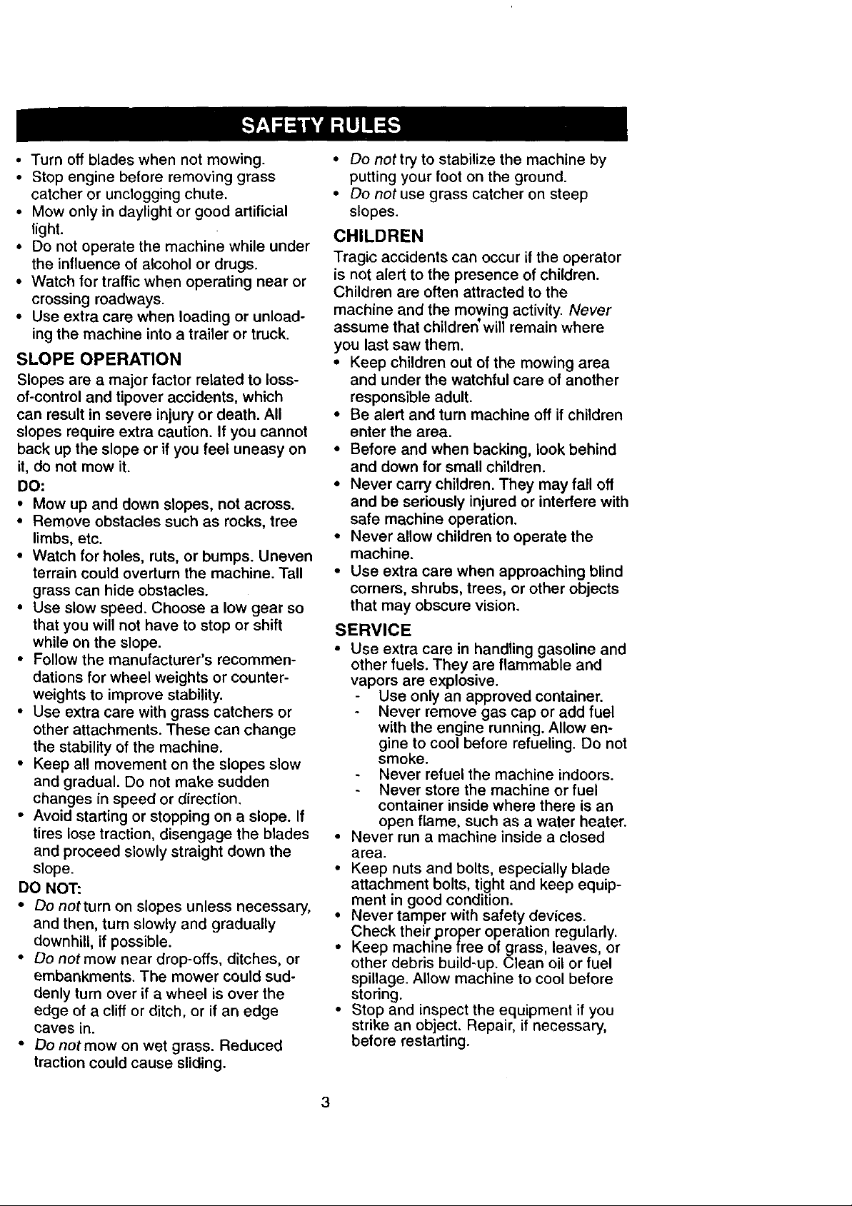
• Turnoffbladeswhennotmowing.
• Stopenginebeforeremovinggrass
catcheror uncloggingchute.
• Mowonlyin daylightor goodartificial
light.
• Donotoperatethemachinewhileunder
theinfluenceofalcoholordrugs.
• Watchfortrafficwhenoperatingnearor
crossingroadways.
• Useextracarewhenloadingorunload-
ingthemachineintoa trailerortruck.
SLOPE OPERATION
Slopes are a major factor related to loss-
of-control and tipover accidents, which
can result in severe injury or death. All
slopes require extra caution. If you cannot
back up the slope or if you feel uneasy on
it, do not mow it.
DO:
• Mow up and down slopes, not across.
• Remove obstacles such as rocks, tree
limbs, etc.
• Watch for holes, ruts, or bumps. Uneven
terrain could overturn the machine. Tall
grass can hide obstacles.
• Use slow speed. Choose a low gear so
that you will not have to stop or shift
while on the slope.
• Follow the manufacturer's recommen-
dations for wheel weights or counter-
weights to improve stability.
• Use extra care with grass catchers or
other attachments. These can change
the stability of the machine.
• Keep all movement on the slopes slow
and gradual. Do not make sudden
changes in speed or direction.
• Avoid starting or stopping on a slope. If
tires lose traction, disengage the blades
and proceed slowly straight down the
slope.
DO NOT:
• Do notturn on slopes unless necessary,
and then, turn slowly and gradually
downhill, if possible.
• Do not mow near drop-offs, ditches, or
embankments. The mower could sud-
denly turn over if a wheel is over the
edge of a cliff or ditch, or if an edge
caves in.
• Do not mow on wet grass. Reduced
traction could cause sliding.
• Do not try to stabilize the machine by
putting your foot on the ground.
• Do not use grass catcher on steep
slopes.
CHILDREN
Tragic accidents can occur if the operator
is not alert to the presence of children.
Children are often attracted to the
machine and the mowing activity. Never
assume that children' will remain where
you last saw them.
• Keep children out of the mowing area
and under the watchful care of another
responsible adult.
• Be alert and turn machine off if children
enter the area.
• Before and when backing, look behind
and down for small children.
• Never carry children. They may fall off
and be seriously injured or interfere with
safe machine operation.
• Never allow children to operate the
machine.
• Use extra care when approaching blind
corners, shrubs, trees, or other objects
that may obscure vision.
SERVICE
• Use extra care in handling gasoline and
other fuels. They are flammable and
vapors are explosive.
Use only an approved container.
Never remove gas cap or add fuel
with the engine running. Allow en-
gine to cool before refueling. Do not
smoke.
Never refuel the machine indoors.
Never store the machine or fuel
container inside where there is an
open flame, such as a water heater.
• Never run a machine inside a closed
area.
• Keep nuts and bolts, especially blade
attachment bolts, tight and keep equip-
ment in good condition.
• Never tamper with safety devices.
Check their proper operation regularly.
• Keep machine free of grass, leaves, or
other debris build-up. Clean oil or fuel
spillage. Allow machine to cool before
storing.
• Stop and inspect the equipment if you
strike an object. Repair, if necessary,
before restarting.
3

• Nevermakeadjustmentsorrepairswith
theenginerunning.
• Grasscatchercomponentsaresubject
towear,damage,and deterioration,
whichcouldexposemovingpartsor
allowobjectsto bethrown.Frequently
checkcomponentsandreplacewith
manufacturer'srecommendedpads,
whennecessary.
• Mowerbladesaresharpandcancut.
Wrapthe blade(s)or weargloves,and
useextracautionwhenservicingthem.
• Checkbrakeoperationfrequently.
Adjustandserviceasrequired.
• Besurethe areaisclearofotherpeople
beforemowing.Stopmachineif anyone
entersthearea.
• Nevercarrypassengers.
o Do not mow in reverse unless absolute-
ly necessary. Always look down and
behind before and while backing.
, Never carry children. They may fall off
and be seriously injured or interfere with
safe machine operation.
, Keep children out of the mowing area
and under the watchful care of another
responsible adult.
, Be alert and turn machine off if children
enter the area.
, Before and when backing, look behind
and down for small children.
_,Look for this symbol to point out impor-
:ant safety precautions. It means CAU-
tION!!! BECOME AWARE!!! YOUR SAFE-
FY IS INVOLVED.
A_.CAUTION: In order to prevent acciden-
al starting when setting up, transporting,
_djusting or making repairs always discon-
lect spark plug wire and place wire where
t cannot contact spark plug.
• Mow up and down slopes (15 ° Max), not
across.
• Remove obstacles such as rocks, tree
limbs, etc.
• Watch for holes, ruts, or bumps. Uneven
terrain could overturn the machine. Tall
grass can hide obstacles.
• Use slow speed. Choose a low gear so
that you will not have to stop or shift
while on the slope.
• Avoid starting or stopping on a slope. If
tires lose traction, disengage the blades
and proceed slowly straight down the
slope.
• Do not turn on slopes unless necessary,
and then, turn slowly and gradually
downhill, if possible.
_,WARNING: The engine exhaust from
this product contains chemicals known to
the State of California to cause cancer,
birth defects, or other reproductive harm.
4

JRODUCT SPECIFICATIONS
GASOLINE 3.5 GALLONS
CAPACITY UNLEADED
AND TYPE: REGULAR
OIL TYPE SAE 30
API-SF/SG/SH): (above 32°F)
SAE 5W-30
(below 32°F)
91L CAPACITY: 3.0 PINTS
;PARK PLUG: Champion RJ19LM
GAP: .030") OR J19LM
_ALVE CLEARANCE: INTAKE: .004-.006
EXHAUST: .007-.009
GROUND SPEED FORWARD: 0- 5.5
MPH): REVERSE: 0-2.4
TIRE PRESSURE: FRONT: 14 PSI
REAR: 10 PSI
CHARGING 16 AMPS@3600
SYSTEM: RPMS
BA]-IERY: AMP/HR: 30
MIN. CCA: 240
CASE SIZE: UIR
BLADE BOLT 27-35 F'[ LBS.
TORQUE:
CONGRATULATIONS on your purchase
of a Craftsman Tractor. It has been
designed, engineered and manufactured
to give you the best possible dependability
and performance.
Should you experience any problem you
cannot easily remedy, please contact your
nearest Sears Authorized Service Center.
We have competent, well-trained techni-
cians and the proper tools to service or
repair this tractor.
Please read and retain this manual. The
instructions will enable you to assemble
and maintain your tractor properly. Always
observe the "SAFETY RULES".
MAINTENANCE AGREEMENT
A Sears Maintenance Agreement is avail-
able on this product. Contact your nearest
Sears store for details.
CUSTOMER RESPONSIBILITIES
• Read and observe the safety rules.
• Follow a regular schedule in maintain-
ing, caring for and using your tractor.
• Follow the instructions under "Mainte-
nance" and "Storage" sections of this
owner's manual.
,_WARNING: This _actor is equipped
with an internal combustion engine and
should not be used on or near any unim-
proved forest-covered, brush-covered or
grass-covered land unless the engine's
exhaust system is equipped with a spark
arrester meeting applicable local or state
laws (if any). If a spark arrester is used, it
should be maintained in effective working
order by the operator.
In the state of California the above is
required by law (Section 4442 of the
California Public Resources Code). Other
states may have similar laws. Federal
laws apply on federal lands. A spark
arrester for the muffler is available through
your nearest Sears Authorized Service
Center (See REPAIR PARTS section of
this manual).

(1) Large Flat Washer
PartsBagcontentsshownfullsize
(1) Hex Bolt 5/16-18 x 1-1/4
e
3/8-16 x 1
(1) Hex Bolt
(1) Lockwasher 3/8
(1) Locknut 5/16-18
(1) Knob
3/16 x 3/4 × 16 Gauge
(2) Washers
(2) Weld
Nuts #10
(1) Washer
17/32 x 1-3/16 x 12 Gauge
__ #10 x 5/8
(1) Shoulder
Bolt 5/16-18
(2) Lock
Washers #10
6
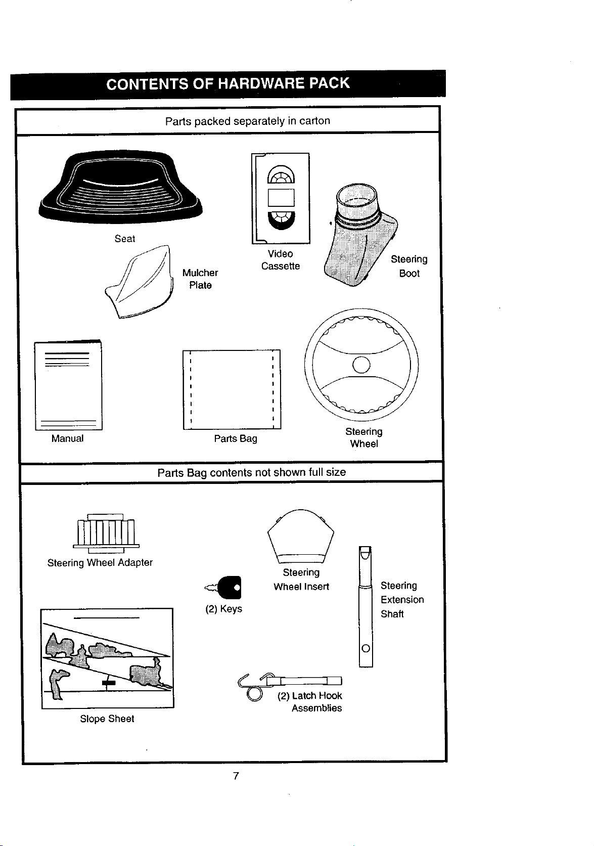
Partspackedseparatelyincarton
Seat
Video
Mulcher
Plate
I
Cassette
Steering
Boot
Manual
L---------.J
Steering Wheel Adapter
Slope Sheet
I
Pa_s Bag
Parts Bag contents not shown full size
Steering
<1
(2) Keys
Wheel Insert Steering
_(_) Latob.'oo_
Assemblies
Steering
Wheel
Extension
Shaft
O

Your new tractor has been assembled at the factory with exception of those parts left
unassembled for shipping purposes• To ensure safe and proper operation of your tractor
all parts and hardware you assemble must be tightened securely. Use the correct tools
as necessary to insure proper tightness. Review the video cassette before you begin.
TOOLS REQUIRED FOR
ASSEMBLY
A socket wrench set will make assembly
easier. Standard wrench sizes you need
are listed below.
(1) 9/16" wrench
(1) 3/4" wrench
(2) 1/2" wrench
(1) Utility knife
(1)Pliers
When right or left hand is mentioned in
this manual, it means, from your point of
view, when you are in the operating posi-
tion (seated behind the steering wheel).
(1) 3/4" Socket w/
drive rachet
(1) Phillips Screw-
driver
(1) Tire pressure
gauge
• Assemble large flat washer, 3/8 lock
washer, 3/8 hex bolt and tighten securely.
• Snap steering wheel insert into center
of steering wheel.
• Remove protective materials from trac-
tor hood and grill_
IMPORTANT: Check for and remove any
staples in skid that may puncture tires
where tractor is to roll off skid.
Insert
, _ 3/8 Hex Bolt
" _3/8 Lockwasher
j _a--_---- Large F/at
_-_:, Washer
TO REMOVE TRACTOR FROM
CARTON
UNPACK CARTON
• Remove all accessible loose parts and
parts boxes from shipping carton (See
page 6).
• Cut, from top to bottom, along lines on
all four corners of shipping carton, and
lay panels flat.
• Check for any additional loose parts or
boxes and remove.
BEFORE ROLLING TRACTOR OFF
SKID
ATTACH STEERING WHEEL
ASSEMBLE EXTENSION SHAFTAND
BOOT
• Slide extension shaft onto lower steer-
ing shaft• Align mounting holes in exten-
sion and lower shafts and install 5/16
hex bolt and Iocknut. Tighten securely.
IMPORTANT: Tighten bolt and nut secure-
ly to 18-22 ft. Ibs. torque.
• Place tabs of steering boot over tab
slots in dash and push down to secure.
INSTALL STEERING WHEEL
• Position front wheels of the tractor so
they are pointing straight forward.
• Slide steering wheel adapter onto steer-
ing shaft extension.
• Position steering wheel so cross bars
are horizontal (left to right) and slide
inside boot and onto adapter.
Steering _ Steering
Wheel oot
Adapter Tabs
Extension
Shaft _ _ 5/16 Hex
Bolt
5/16 Lockn_//
Lower Steermg...._p...._._, o_ - _'--- -,
Shaft ,7 "q, _ -, ,
L "-. _ Tab
....-. , , Slots
TO ROLL TRACTOR OFF SKID (See
Operation section for location and
function of controls)
• Press lift lever plunger and raise attach-
ment lift lever to its highest position.
• Release parking brake by depressing
clutch/brake pedal•
• Place freewheel control in freewheeling
position to disengage transmission (See
"TO TRANSPORT" in the Operation
section of this manual)•
• Roll tractor forward off skid.
• Remove banding holding discharge
guard up against tractor•
8

HOW iO SET UP YOUR TRACTOR
CHECK BATTERY
• Lift hood to raised position.
• If this battery is put into service after
month and year indicated on label (label
located between terminals) charge bat-
tery for minimum of one hour at 6-10
amps. (See "BATTERY" in MAINTE-
NANCE section of this manual for
charging instructions).
INSTALL SEAT"
Adjust seat before tightening adjustment
knob.
• Remove cardboard packing on seat
pan.
• Place seat on seat pan and assemble
shoulder bolt. Tighten shoulder bolt
securely.
• Assemble adjustment knob and flat
washer loosely. Do not tighten.
• Lower seat into operating position and
sit on seat.
• Slide seat until a comfortable position is
reached which allows you to press
clutch/brake pedal all the way down.
• Get off seat without moving its adjusted
position.
• Raise seat and tighten adjustment knob
securely.
Seat
Seat Pan
Shoulder
Bolt
INSTALL MULCHER PLATE
• Install two latch hooks to mulcher plate
using screw, washer, lock washer, and
weld nut as shown.
NOTE: Pre-assemble weld nut to latch
hook by inserting weld nut from the top
with hook pointing down.
• Tighten hardware securely.
• Raise and hold deflector shield in up-
right position.
• Place front of mulcher plate over front of
mower deck opening and slide into
place, as shown_
• Hook front latch into hole on front of
mower deck.
• Hook rear latch into hole on back of
mower deck.
,ACAUTION: Do not remove discharge
guard from mower. Raise and hold guard
when attaching mulcher plate and allow it
to rest on plate while in operation.
TO CONVERT TO BAGGING OR
DISCHARGING
Simply remove mulcher plate and store in
a safe place. Your mower is now ready for
discharging or installation of optional
grass catcher accessory.
NOTE: It is not necessary to change
blades. The mulcher blades are designed
for discharging and bagging also.
Weld Nut From Hook Points
The Top \ Down
Lock
Weld Washer
Nut
"._j Screw
Latch
Hook
Washer
Mulcher ¥._Screw
Plate
Deflector ,_
Lock Washer
Washer
Latch
Hook
IdNut
Adjustment Knob
Flat Washer
,_r Latch
Hooks
9

CHECKTIREPRESSURE
Thetiresonyourtractorwereoverinflated
at the factory for shipping purposes.
Correct tire pressure is important for best
cutting performance.
• Reduce tire pressure to PSI shown in
"PRODUCT SPECIFICATIONS" on
page 5 of this manual.
CHECK DECK LEVELNESS
For best cutting results, mower housing
should be properly leveled. See "TO
LEVEL MOWER ROUSING" in the
Service and Adjustments section of this
manual.
CHECK FOR PROPER POSITION OF
ALL BELTS
See the figures that are shown for replac-
ing motion and mower blade drive belts in
the Service and Adjustments sectoin of
this manual. Verify that the belts are rout-
ed correctiy.
CHECK BRAKE SYSTEM
After you learn how to operate your trac-
tor, check to see that the brake is propedy
adjusted. See "TO ADJUST BRAKE" in
the Service and Adjustments section of
this manual.
v"CHECKLIST
PLEASE REVIEW THE FOLLOWING
CHECKLIST:
I#' All assembly instructions have been
completed.
v' No remaining loose parts in carton.
v' Battery is properly prepared and
charged. (Minimum 1 hour at 6 amps).
v' Seat is adjusted comfortably and
tightened securely.
v' All tires are prop,erly inflated. (For
shipping purposes, the tires were
overinflated at the factory).
_" Be sure mower deck is properly leveled
side-to-side/front-to-rear for best
cutting results. (Tires must be properly
inflated for leveling).
is' Check mower and drive belts. Be sure
they are routed properly around pulleys
and inside all belt keepers.
v" Check wiring. See that all connections
are still secure and wires are properly
clamped.
Before driving tractor, be sure free-
wheel control is in drive position.
WHILE LEARNING HOW TO USE YOUR
TRACTOR, PAY EXTRAATTENTION TO
THE FOLLOWING IMPORTANT ITEMS:
,/ Engine oil is at proper level.
V" Fuel tank is filled with fresh, clean,
regular unleaded gasoline.
,/ Become familiar with all controls - their
location and function. Operate them
before you start the engine.
•/ Be sure brake system is in safe operat-
ing condition.
,/ It is important to purge the transmis-
sion before operating your tractor for
the first time. Follow proper starting
and transmission purging instructions
(See "TO START ENGINE" and
"PURGE TRANSMISSION" in the Op-
eration section of this manual).
10
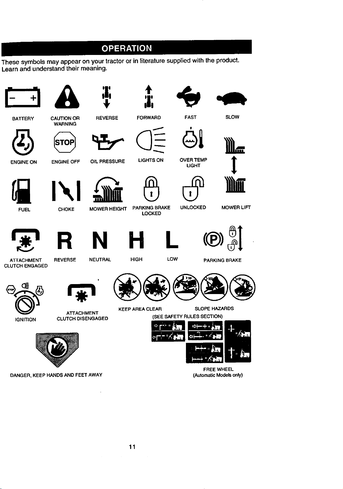
Thesesymbolsmayappearonyourtractororin literature supplied with the product.
Learn and understand their meaning.
BATTERY CAUTION OR REVERSE FORWARD FAST SLOW
WARNING
FUEL CHOKE MOWER HEIGHT PARKING BRAKE UNLOCKED MOWER LIFT
LOCKED
R N H L
ATTACHMENT REVERSE
CLUTCH ENGAGED
(_) _ KEEP AREA CLEAR SLOPE HAZARDS
ATTACHMENT
IGNITION CLUTCH DISENGAGED (SEE SAFETY RULES SECTION)
DANGER, KEEP HANDS AND FEET AWAY
NEUTRAL HIGH LOW PARKING BRAKE
FREE WHEEL
(AutomaticModelsonly)
11

KNOW YOUR TRACTOR
READ THIS OWNER'S MANUAL AND SAFETY RULES BEFORE OPERATING YOUR
TRACTOR
Compare the illustrations with your tractor to familiarize yourself with the locations of
various controls and adjustments. Save this manual for future reference,
Light Switch
Attachment Ignition
Clutch Lever Switch
Amme_r
Choke
Position
Throttle Control
Clutch/Brake
Pedal
Height
Adj_
Knob
Freewheel
Control
Lift Lever
Plunger
Attachment
LiftLever
Parking Brake
Motion
Control Lever
Our tractors conform to the safety standards of the American
National Standards Institute.
AI-I'ACHMENT CLUTCH LEVER: Used to
engage the mowerblades, or other attachments
mounted to your tractor.
LIGHT SWITCH: Turns the headlights on and
off.
CHOKE CONTROL: Used when starting a cold
engine.
THROTTLE CONTROL: Used to control engine
speed.
CLUTCH/BRAKE PEDAL: Used fordeclutch-
ingand brakingthe tractorand startingthe
engine.
FREEWHEEL CONTROL: Disengages trans-
mission for pushing or slowly towing the tractor
with the engine off.
HEIGHT ADJUSTMENT KNOB: Used to adjust
the mower cutting height.
MOTION CONTROL LEVER: Selects the
speed and directionof the tractor.
ATTACHMENT LIFT LEVER: Used to raise and
lower the mower deck or other attachments
mounted to yourtractor.
LIFT LEVER PLI,INGER: Used to release
attachment lift lever when changingits position.
IGNITION SWITCH: Used for starting and stop-
ping the engine.
AMMETER: Indicates battery charging (+) or
discharging (-).
PARKING BRAKE: Locks clutch/brake intothe
brake position.
12
eyes, which can result in severe eye damage. Always wear safety glasses
or eye shields while operating your tractor or performing any adjustments or
I_ he operation of any tractor can result in foreign objects thrown into the
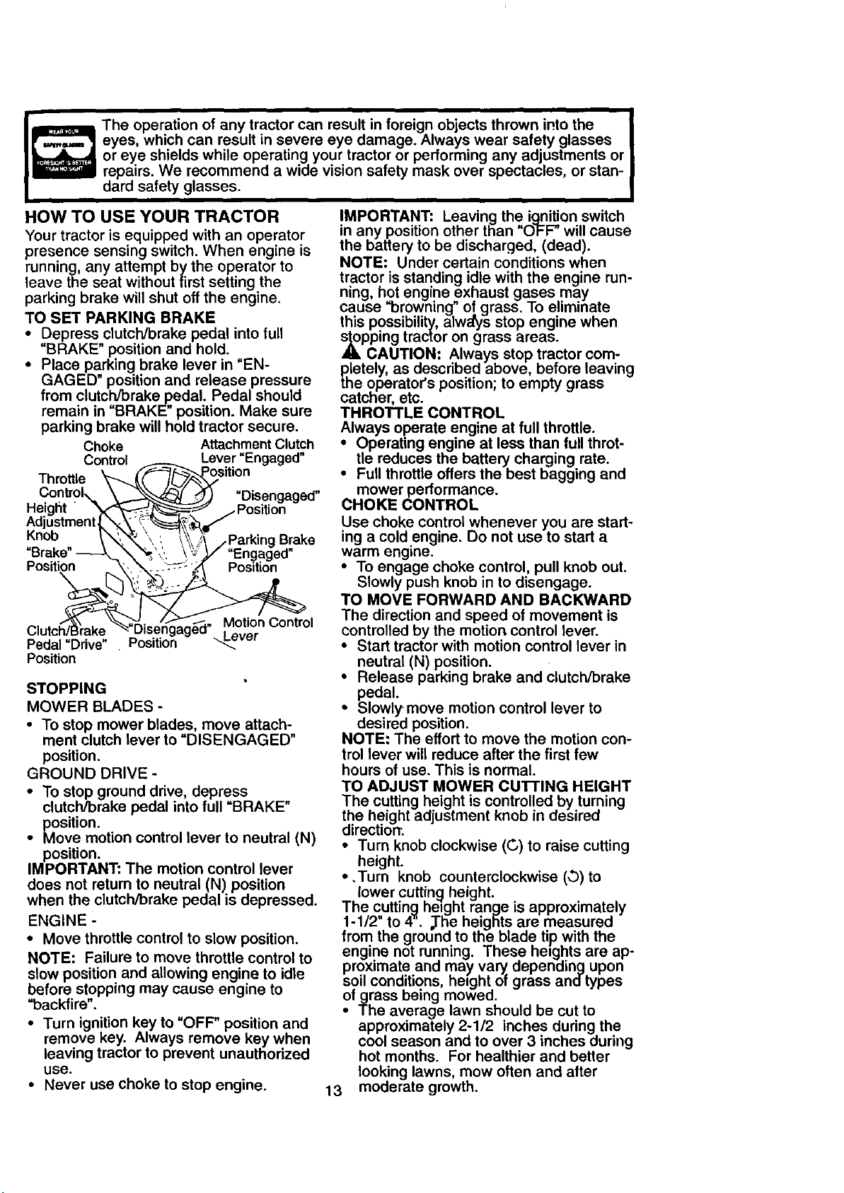
HOW TO USE YOUR TRACTOR IMPORTANT: Leaving the ignition switch
Your tractor is equipped with an operator in any position other than "O_FF" will cause
presence sensing switch. When engine is the battery to be discharged, (dead).
running, any attempt by the operator to NOTE: Under certain conditions when
leave the seat without first setting the tractor is standing idle with the engine run-
parking brake will shut off the engine, cause "browning" of grass. To eliminate
TO SET PARKING BRAKE this possibility, always stop engine when
• Depress clutch/brake pedal into full s_opping tractor on grass areas.
"BRAKE" position and hold. A CAUTION. Always stop tractor corn-
• Place parking brake lever in "EN- pletely, as described above, before leaving
GAGED" position and release pressure the operator's position; to empty grass
from clutch/brake pedal. Pedal should catcher, etc.
remain in "BRAKE" position. Make sure THROTTLE CONTROL
parking brake will hold tractor secure. Always operate engine at full throttle.
Throttle _..._.((,_._--_sitio n
ControIx. \_..'_--,_ _ =Disengaged" mower performance.
Height "_- _-:_ ...Position
Adjustment L_ _ __!L_e, ,/
Knob _,'_.,._'\ ', _\ ,!_"/Parking Brake
Brake" -----_._'_,_ _"_'.}/ "Engaged"
Position -_, _-" =.:'--'_"__" Position
Clutch" M°vtie°rnContr(
Pedal "Ddve" Position _ _"
Position neutral (N) position.
STOPPING pedal.
MOWER BLADES - • Slowly. move motion control lever to
• To stop mower blades, move attach- desired position.
ment clutch lever to "DISENGAGED" NOTE: The effort to move the motion con-
position, trol lever will reduce after the first few
GROUND DRIVE - hours of use. This is normal.
• To stop ground drive, depress TO ADJUST MOWER cu'n'ING HEIGHT
clutch/brake pedal into full "BRAKE" The cutting height is controlled by turning
position, the height adjustment knob in desired
• Move motion control lever to neutral (N) • Turn knob clockwise (C) to raise cutting
position, height.
IMPORTANT: The motion control lever
does not return to neutral (N) position * ,Turn knob counterclockwise (,.3) to
when the clutch/brake pedal is depressed. The cutting height range is approximately
ENGINE - 1-1/2" to 44. _he heigfits are measured
• Move throttle control to slow position, from the ground to the blade tip with the
NOTE: Failure to move throttle control to engine not running. These heights are ap-
slow position and allowing engine to idle soil conditions, height of grass and-types
before stopping may cause engine to of grass being mowed.
"backfire".
• Turn ignition key to "OFF" position and approximately 2-1/2 inches during the
remove key. Always remove key when cool season and to over 3 inches during
leaving tractor to prevent unauthorized hot months. For healthier and better
use. looking lawns, mow often and after
• Never use choke to stop engine. 13 moderate growth.
repairs. We recommend a wide vision safety mask over spectacles, or stan-
dard safety glasses.
ning, hot engine exhaust gases may
Choke Attachment Clutch ,, Operating engine at less than full throt-
Control
Lever "Engaged" • tie reduces the battery charging rate.
_, Motion Control
Full throttle offers the best bagging and
CHOKE CONTROL
Use choke control whenever you are start-
ing a cold engine. Do not use to start a
warm engine.
• To engage choke control, pull knob out.
Slowly push knob in to disengage.
TO MOVE FORWARD AND BACKWARD
The direction and speed of movement is
controlled by the motion control lever.
• Start tractor with motion control lever in
• Release parking brake and clutch/brake
direction.
lower cutting height.
proximate and may vary_depending upon
• The average lawn should be cut to
• For best cutting performance, grass
over 6 inches in height shouldbe
mowed twice. Make the first cut rela-
tively high; the second to desired height.
TO ADJUST GAUGE WHEELS
Gauge wheels are properly adjusted
when they are slightly off the ground when
mower is at the desired cutting height in
operatingposition. Gauge wheels then
keep the deck in proper position to help
prevent scalping in most terrain condi-
tions.
• Adjust gauge wheels with tractor on a
flat level surface.
• Adjust mower to desired cutting height
(See "TO ADJUST MOWER CUI-rlNG
HEIGHT" in the Operation section of
this manual).
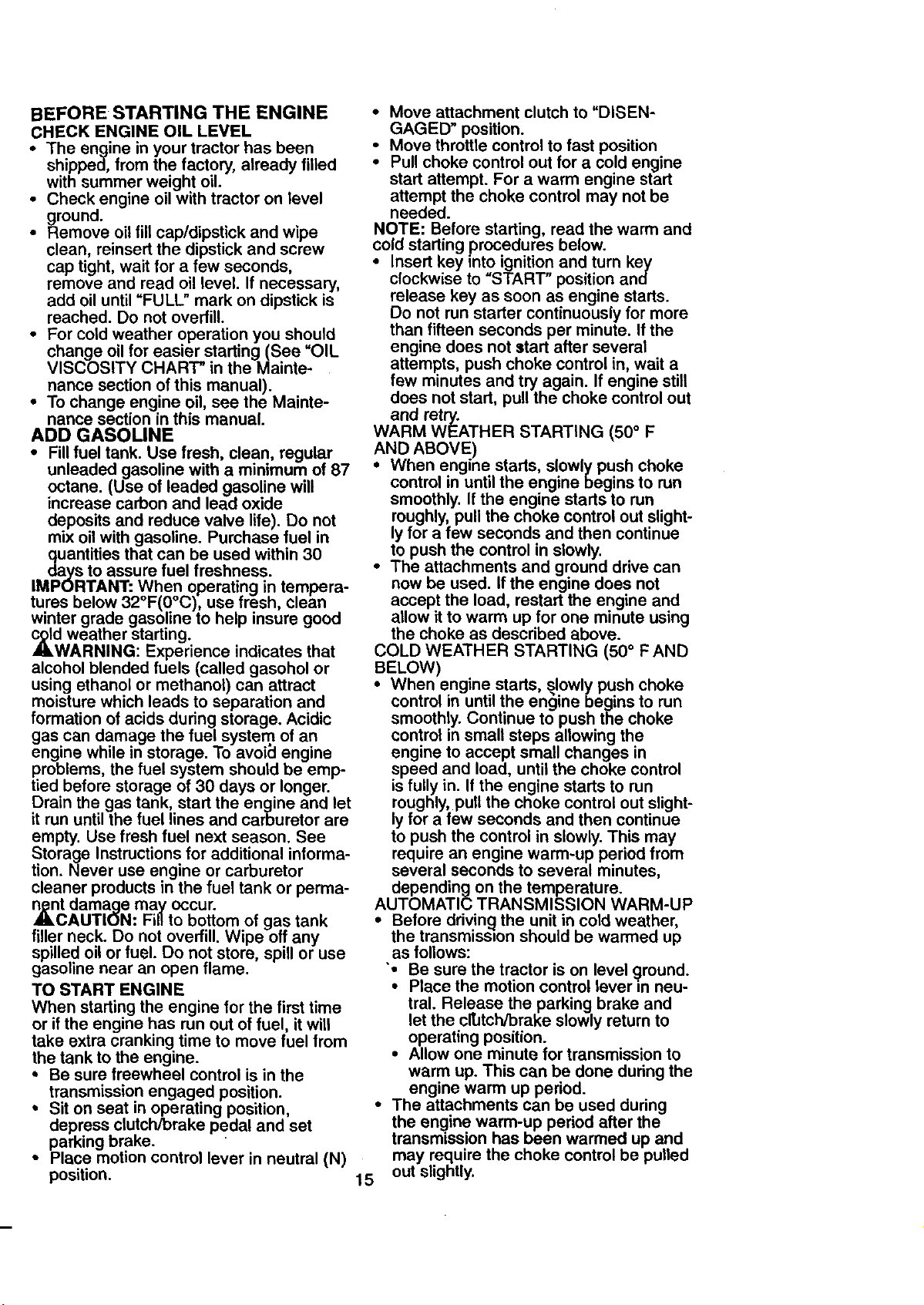
• With mower in desired height of cut po-
sition, gauge wheels should be assem-
bled so they are slightly off the ground.
Install gauge wheel in appropriate hole
with shoulder bolt, 3/8 washer, and 3/8-
16 Iocknut and tighten securely.
• Repeat for opposite side installing
gauge wheel in same adjustment hole.
3/8-16 o_
Locknut_ -.
Gauge Wheel
Mounting
3/8 Washer """ J
Gaug_ Shoulder
TO OPERATE MOWER
Your tractor is equipped with an operator
presence sensing switch. Any attempt by
the operator to leave the seat with the
engine runnmgand the attachment clutch
engaged will shut off the engine.
• Select desired height of cut.
• Lower mower with attachment lift con-
trol.
• Start mower blades by engaging attach-
ment clutch control.
• TO STOP MOWER BLADES - disen-
gage attachment clutch control.
_ OPERATE ON HILLS
CAUTION: Do not drive up or down
hills with slopes greater than 15 ° and do
not drive across any slope. Use the slope
guide provided at the back of this manual.
• Choose the slowest speed before start-
ing up or down hills.
• Avoid stopping or changing speed on
hills.
If slowing is necessary, move throttle
control lever to slower position.
If stopping is absolutely necessary, pusl'f
clutch/brake pedal quickly to brake posi-
tion and engage parking brake, cause you to lose control of your tractor.
Bolt
• Move motion control lever to neutral (N)
position.
IMPORTANT: The motion control lever
does not return to neutral (N) position
when the clutch/brake pedal is depressed.
• To restart movement, slowly release
parking brake and clutch/brake pedal.
• Slowly move motion control lever to
slo_Nest setting.
• Make all turns slowly.
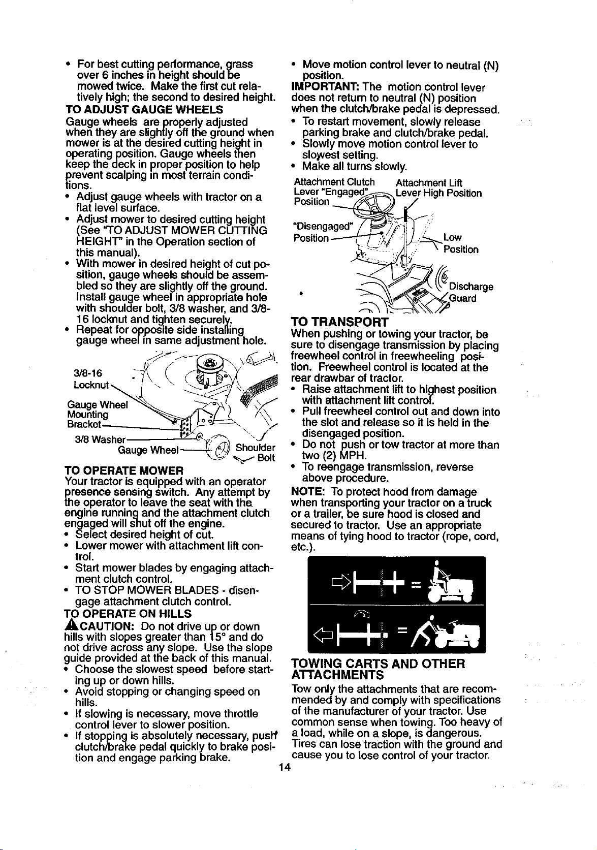
Attachment Clutch Attachment Lift
Lever "En( Lever High Position
Position
=Disengaged"
TO TRANSPORT
When pushing or towing your tractor, be
sure to disengage transmission by placing
freewheel control in freewheeling posi-
tion. FTeewheel control is located at the
rear drawbar of tractor.
• Raise attachment lift to highest position
with attachment lift control.
• Pull freewheel control out and down into
the slot and release so it is held in the
disengaged position.
• Do not push or tow tractor at more than
two (2) MPH.
• To reengage transmission, reverse
above procedure.
NOTE: To protect hood from damage
when transporting your tractor on a truck
or a trailer, be sure heed is closed and
secured to tractor. Use an appropriate
means of tying hood to tractor (rope, cord,
etc.).
Low
Position
TOWING CARTS AND OTHER
ATTACHMENTS
Tow only the attachments that are recom-
mended by and comply with specifications
of the manufacturer of your tractor. Use
common sense when towing. Too heavy of
a load, while on a slope, is dangerous.
Tires can lose traction with the ground and
14
BEFORE STARTING THE ENGINE
CHECK ENGINE OIL LEVEL
• The engine in your tractor has been
shipped, from the factory, already filled
with summer weight oil.
• Check engine oil with tractor on level
ground.
• Remove oil fill cap/dipstick and wipe
clean, reinsert the dipstick and screw
cap tight, wait for a few seconds,
remove and read oil level. If necessary,
add oil until "FULL" mark on dipstick is
reached. Do not overfill.
• For cold weather operation you should
change oil for easier starting (See "OIL
VISCOSITY CHART" in the Mainte-
nance section of this manual).
• To change engine oil, see the Mainte-
nance section in this manual.
ADD GASOLINE
• Fill fuel tank. Use fresh, clean, regular
unleaded gasoline with a minimum of 87
octane. (Use of leaded gasoline will
increase carbon and lead oxide
deposits and reduce valve life). Do not
mix oil with gasoline. Purchase fuel in
quantities that can be used within 30
days to assure fuel freshness.
IMPORTANT: When operating in tempera-
tures below 32°F(0°C), use fresh, clean
winter grade gasoline to help insure good
cold weather starting.
AILWARNING: Experience indicates that
alcohol blended fuels (called gasohol or
using ethanol or methanol) can attract
moisture which leads to separation and
formation of acids during storage. Acidic
gas can damage the fuel system of an
engine while in storage. To avoid engine
problems, the fuel system should be emp-
tied before storage of 30 days or longer.
Drain the gas tank, start the engine and let
it run until the fuel lines and carburetor are
empty. Use fresh fuel next season. See
Storage Instructions for additional informa-
tion. Never use engine or carburetor
cleaner products in the fuel tank or perma-
_nct damage may occur.
AUTION: Fiflto bottom of gas tank
filler neck. Do not overfill. Wipe off any
spilled oil or fuel. Do not store spill or use
gaso ne near an open f ame.
TO START ENGINE
When starting the engine for the first time
or if the engine has run out of fuel, it will
take extra cranking time to move fuel from
the tank to the engine.
• Be sure freewheel control is in the
transmission engaged position.
• Sit on seat in operating position,
depress clutch/brake pedal and set
parking brake.
• Place motion control lever in neutral (N)
position.
• Move attachment clutch to "DISEN-
GAGED" position.
Move throttle control to fast position
Pull choke control out for a cold engine
start attempt. For a warm engine start
attempt the choke control may not be
needed.
NOTE: Before starting, read the warm and
cold starting procedures below.
• Insert key into ignition and turn key
clockwise to "START" position and
release key as soon as engine starts.
Do not run starter continuously for more
than fifteen seconds per minute. If the
engine does not start after several
attempts, push choke control in, wait a
few minutes and try again. If engine still
does not start, pull the choke control out
and retry.
WARM WEATHER STARTING (50 ° F
AND ABOVE)
When engine starts, slowly push choke
control in until the engine begins to run
smoothly. If the engine starts to run
roughly, pull the choke control out slight-
ly for a few seconds and then continue
to push the control in slowly.
• The attachments and ground drive can
now be used. If the engine does not
accept the load, restart the engine and
allow it to warm up for one minute using
the choke as described above.
COLD WEATHER STARTING (50 ° F AND
BELOW)
• When engine starts, slowly push choke
control in until the engine begins to run
smoothly. Continue to push the choke
control in small steps allowing the
engine to accept small changes in
speed and load, until the choke control
is fully in. If the engine starts to run
roughly, pull the choke control out slight-
ly for a few seconds and then continue
to push the control in slowly. This may
require an engine warm-up period from
several seconds to several minutes,
depending on the temperature.
AUTOMATIC TRANSMISSION WARM-UP
• Before ddvincj the unit in cold weather,
the transmisston should be warmed up
as follows:
• Be sure the tractor is on level _]round.
Place the motion control lever =nneu-
tral. Release the parking brake and
let the cltJtch/brake slowly return to
operating position.
• Allow one minute for transmission to
warm up. This can be done during the
engine warm up period.
• The attachments can be used during
the engine warm-up period after the
transmission has been warmed up and
may require the choke control be pulled
15 out slightly.
NOTE:Ahighaltitude(above3000feet)
or in cold temperatures (below 32 F) the
carburetor fuel mixture may need to be
adjusted for best engine performance.
See "TO ADJUST CARBURETOR" in the
Service and Adjustments section of this
manual.
P_RGE TRANSMISSION
CAUTION. Never engage or disen-
gage freewheel lever wh_le the engine is
running.
To ensure proper operation and perfor-
mance, it is recommended that the trans-
mission be purged before operating tractor
for the first time. This procedure wm
remove any trapped air inside the trans-
mission which may have developed during
shippingof your tractor.
IMPORTANT: Should your transmission
require removal for service or replace-
ment, it should be purged after reinstalla-
t=onbefore operating the tractor.
• Place tractor safely on level surface with
engine off and parking brake set.
• Disengage transmission by placing free-
wheel control in freewheeling position
(See "TO TRANSPORT" in this section
of manual).
• Sitting in the tractor seat, start engine.
After the engine is running, move throt-
tle control to slow position. With motion
control lever in neutral (N) position,
slowly disengage clutch/brake pedal.
• Move motion control lever to full forward
position and hold for five (5) seconds.
Move lever to full reverse position and
hold for five (5) seconds. Repeat this
procedure three (3) times.
NOTE: During this procedure there will be
no movement of dnve wheels. The air is
being removed from hydraulic drive sys-
tem.
• Move motion control lever to neutral (N)
position. Shut off engine and set parking
brake.
• Engage transmission by placing free-
whee/control in driving position (See
"TO TRANSPORT" in this section of
manual).
• Sitting in the tractor seat, start engine.
After the engine is running, move throt-
tle control to half (1/2) speed. With
motion control lever in neutral (N) posi-
tion, slowly disengage clutch/brake
pedal.
• Slowly move motion control lever for-
ward; after the tractor moves approxi-
mately five (5) feet, slowly move motion
control lever to reverse position. After
the tractor moves approximately five (5)
feet return the motion control lever to
the neutral (N) position. Repeat this pro-
cedura with the motion control lever
three (3) times.
• Your tractor is now purged and ready for
normal operation.
MOWING TIPS
• Tire chains cannot be used when the
mower housing is attached to tractor.
• Mower should be properly leveled for
best mowing performance. See "TO
LEVEL MOWER HOUSING" in the
Service and Adjustments section of this
manual.
• The left hand side of mower should be
used for trimming.
• Drive so that clippings are discharged
onto the area that has been cut. Have
the cut area to fife right of the tractor.
This will result in a more even distribu-
tion of clippings and more uniform cut-
ting.
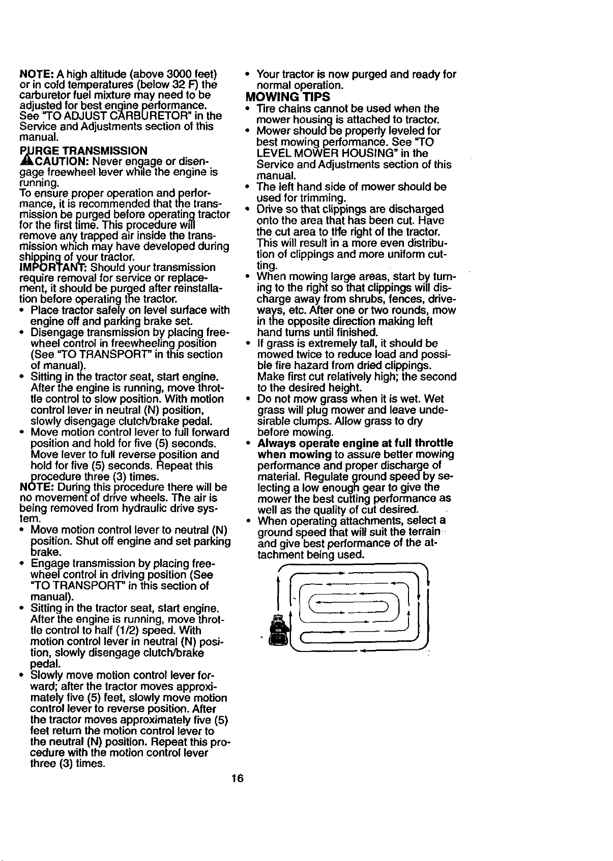
• When mowing large areas, start by turn-
ing to the right so that clippings will dis-
charge away from shrubs, fences, drive-
ways, etc. After one or two rounds, mow
in the opposite direction making left
hand turns until finished.
• If grass is extremely tall, it should be
mowed twice to reduce load and possi-
ble fire hazard from dried clippings.
Make first cut relatively high; the second
to the desired height.
• Do not mow grass when it is wet. Wet
grass will plug mower and leave unde-
sirable clumps. Allow grass to dry
before mowing.
• Always operate engine at full throttle
when mowing to assure better mowing
performance and proper discharge of
material. Regulate ground speed by se-
lecting a low enough gear to give the
mower the best cutting performance as
well as the quality of cut desired.
• When operating attachments, select a
ground speed that will suit the terrain:,
and give best performance of the at-
tachment being used.
" li
, 4 .
16
MULCHING MOWING TIPS
IMPORTANT: For best performance, keep
mower housing free of built-up grass and
trash. Clean after each use.
• The special mulching blade will recut
the grass clippings many times and
reduce them in size so that as they fall
onto the lawn they will disperse into the
grass and not be noticed. Also, the
mulched grass will biodegrade quickly
to provide nutrients for the lawn. Always
mulch with your highest engine (blade)
speed as this will provide the best recut-
ting action of the blades.
• Avoid cutting your lawn when it is wet.
Wet grass tends to form clumps and
interferes with the mulching action. The
best time to mow your lawn is the early
afternoon. At this time the grass has
dried and the newly cut area will not be
exposed to the direct sun.
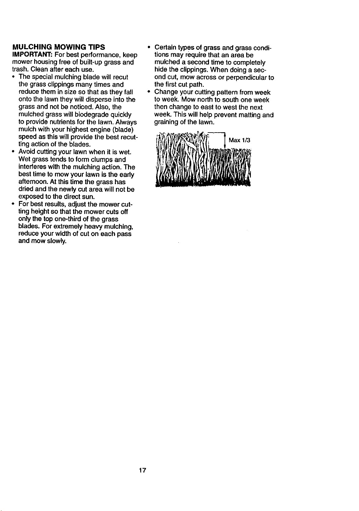
• For best results, adjust the mower cut-
ting height so that the mower cuts off
only the top one-third of the grass
blades. For extremely heavy mulching,
reduce your width of cut on each pass
and mow slowly.
• Certain types of grass and grass condi-
tions may require that an area be
mulched a second time to completely
hide the clippings. When doing a sec-
ond cut, mow across or perpendicular to
the first cut path.
• Change your cutting pattern from week
to week, Mow north to south one week
then change to east to west the next
week. This will help prevent matting and
graining of the lawn.
•, f i
17
AsF'LLyouMAINTENANCESCHEDULEiNDATEScOMPLETE __d_" '_'_ '_'_''_°e'_-'_-"_'_I"_._._'_,_".,_=_7;_"':_',_o_;_,,o_
.EGU RSERV,CE Y OATES
c__o,o.o.,.,.°
Check Tire Pressure
Check Operator Presence and
T interlock Systems
R Cr.Bck for Loose Fasteners ;V' 11_7 I_
T Lubrication Chart ll_e
0 Check Battery Level
A Sharpen/Replace Mower Blades _4
R Clean Battery and Terminals l# /
Check Transaxla Cooling
Adjust Blade BaR(s) Tension Ks
Adjust Motion Drive BaR(S) Tension
Check Engine Oil Level _
Change Engine Oil !1_1.,_ I_
E Clean Air Filter Ik_2
N Clean Air Screen _2
IG Inspect Muffler/Spark Arrester Ik/
Replace Oil Filter (If equipped) ._.=N
S Clean Engine Cooling Fins
Replace Spark plug _2 I_
Replace Air Filter Paper Cartridge 1_2
Replace Fuel Filter Ikf
1 - Change mcce often when operating under a heavy load o_"in high ambient temperatures, g - If equipped with ao*jus,_able system.
2 - Service more often when c_perating in dirty or dusty cond;_ons. 6 ° Not required if equipped with mmintenance-free batter
3 - If equipped with oil filter, change oll eveP/50 hours. 7 - Tighten front exle _ bolt to 35 ft,- f_s. meximurn,
4 - Replace oiades rnoceoftenwhen mowing in sandy soil. DOnotor=tighten. •
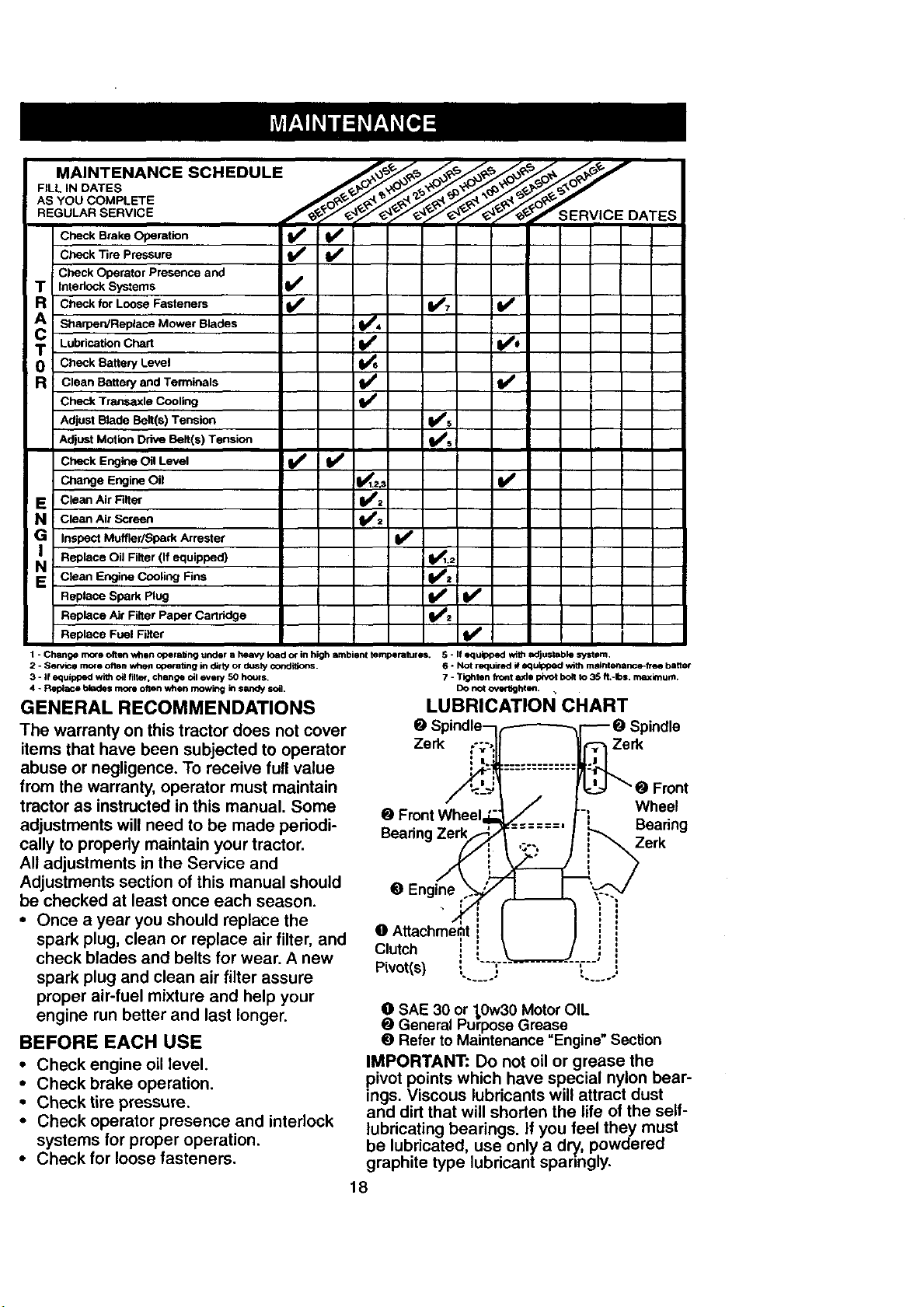
GENERAL RECOMMENDATIONS LUBRICATION CHART
The warranty on this tractor does not cover
items that have been subjected to operator Zerk
abuse or negligence. To receive full value
from the warranty, operator must maintain
tractor as instructed in this manual. Some 0
adjustments will need to be made periodi- Bearin,
cally to propedy maintain your tractor.
All adjustments in the Service and
Adjustments section of this manual should 0 Engine
be checked at least once each season.
• Once a year you should replace the
spark plug, clean or replace air filter, and
check blades and belts for wear. A new Clutch
spark plug and clean air filter assure Pivot(s)
proper air-fuel mixture and help your
engine run better and last longer.
BEFORE EACH USE
• Check engine oil level.
• Check brake operation.
• Check tire pressure.
• Check operator presence and interlock
systems for proper operation.
• Check for loose fasteners.
IMPORTANT: Do not oil or grease the
pivot points which have special nylon bear-
ings. Viscous lubricants will attract dust
and dirt that will shorten the life of the self-
lubricating bearings, if you feel they must
be lubricated, use only a dry, powdered
graphite type lubricant spanngly.
18
v',
Zerk
Wheel
Bearing
Zerk
_SAE 30 or 1,0w30Motor OIL
General Purpose Grease
0 Refer to Maintenance "Engine" Section
 Loading...