

Craftsman 917270813 Owner’s Manual

Owner's Manual
£RRFfSMR#
19.5HP
ELECTRIC START
42" MOWER
6 SPEED TRANSAXLE
LAW TRACTOR
Model No.
917.2708t3
• Safety
• Assembly
° Operation
oMaintenance
• Repair Parts
CAUTION:
Read and follow all Safety
Rules and Instructions before
operating this equipment.
For answers to your questions
about this product, CaEI:
1-800-659-5917
Sears Craftsman Help Line
5 am - 5 pro, Mon- Sat
Sears, Roebuck and Co., Hoffman Estates, II60179
Visit our Craftsman website:wwwsearscom/craftsman

Warranty........................................................2
SafetyRules.............................................2
ProductSpecifications..............................5
Assembly...................................................8
Operation.......................................................11
MaintenanceSchedule......................17
Maintenance..................................................17
ServiceandAdjustments.....................21
Storage............................................................27
Troubleshooting..........................................28
RepairParts..................................................32
PartsOrdering.....................Back Cover
LIMITEDTWOYEARWARRANTYONCRAFTSMANRIDINGEQUIPMENT
Fortwo(2)yearsfromthedateof purchase,if thisCraftsmanRidingEquipmentis
maintained,lubricatedandtuned upaccordingtothe instructionsintheowner's
manual,Searswilt repairor replace,freeof charge,any partsfoundto be defectivein
materialor workmanship.
ThisWarrantydoesnotcover:
• Expendableitemswhichbecomewornduringnormaluse, suchas blades,spark
plugs,air cleaners,belts,etc.
• Tire replacementor repaircausedby puncturesfromoutsideobjects,suchas nails,
thorns,stumps,or glass.
- Repairsnecessarybecauseof operatorabuse,negligence,improperstorageor
accidentor thefailureto maintaintheequipmentaccordingto the instructions
containedinthe owner'smanual.
• Ridingequipmentusedfor commercialor rentalpurposes_
LIMITED90DAYWARRANTYONBATTERY
Forninety(90)daysfromdate of purchase,if any batteryincludedwiththisriding
equipmentprovesdefectivein materialor workmanshipandour testingdeterminesthe
batterywillnot holda charge,Searswill replacethebatteryat no charge.In-home
warrant,]serviceonyour Craftsmanridingequipmentis availableat no chargefor 30
daysfrom thedateof purchase.Pleasecontactyournearestservicecenter.After 30
daysfrom thedateof purchase,warrantyserviceis availablebytakingyour Craftsman
ridingequipmentto your nearestSearsServiceCenter:(In-homewarrantyservicewill
still beavailableafter30 daysfromthedateof purchasebutastandardtripchargewill
apply)..Thiswarrantyappliesonlywhilethisproductis inthe UnitedStates.This
Warrantygivesyou specificlegalrights,andyou mayalsohaveotherrightswhichmay
varyfromstateto state.
SEARS,ROEBUCKANDCO..,D/817WA,HOFFMANESTATES,IL 60179
IMPORTANT:Thiscuttingmachineis
capableof amputatinghandsandfeet
andthrowingobjects Failuretoobserve
thefollowingsafetyinstructionscould
resultin seriousinjuryor death.
GENERA[. OPERATION
, Read, understand, and follow all
instructions in the manual and on the
machine before starting.
• Only allow responsible adults, who are
familiar with the instructions, to
operate the machine.
• Clear the area of objects such as
rocks, toys, wire, etc., which could be
picked up and thrown by the blade..
• Be sure the area is clear of other
people before mowing. Stop machine
if anyone enters the area..
• Never carry passengers.
• Do not mow in reverse unless abso-
lutely necessary. Always look down
and behind before and while backing.
• Be aware of the mower discharge
direction and do not point it at anyone°
Do not operate the mower without
either the entire grass catcher or the
guard in place..
2

, Slowdown beforeturning.
• Neverleavea runningmachine
unattended.Alwaysturnoff blades,set
parkingbrake,stop engine, and
remove keys before dismounting
• Stop engine before removing grass
catcher or unclogging chute.
• Mow only in daylight or good artificial
light°
• Do not operate the machine white
under the influence of alcohol or
drugs..
• Watch for traffic when operating near
or crossing roadways..
• Use extra care when loading or
unloading the machine into a trailer or
truck.
• Data indicates that operators, age 60
years and above, are involved in a
large percentage of riding mower-
related injuries. These operators
should evaluate their ability to operate
the riding mower safely enough to
protect themselves and others from
serious injury°
SLOPE OPERATION
Slopes are a major factor related to loss-
of-control and tipover accidents, which
can result in severe injury or death. All
slopes require extra caution. If you
cannot back up the slope or if you feel
uneasy on it, do not mow it.
DO:
• Mow up and down slopes, not across.
• Remove obstacles such as rocks, tree
limbs, etc
• Watch for holes, ruts, or bumps°
Uneven terrain could overturn the
machine. Tall grass can hide ob-
stacles,
• Use slow speed. Choose a low gear
so that you will not have to stop or shift
while on the slope.
• Follow the manufacturer's recommen-
dations for wheel weights or counter-
weights to improve stability.
• Use extra care with grass catchers or
other attachments, These can change
the stability of the machine.
° Keep all movement on the slopes slow
and gradual.. Do not make sudden
changes in speed or direction.,
• Avoid starting or stopping on a slope. If
tires lose traction, disengage the
blades and proceed slowly straight
down the slope.,
DO NOT:
• Do not turn on slopes unless neces-
sary, and then, turn slowly and
gradually downhill, if possible.
• Do not mow near drop-offs, ditches, or
embankments, The mower could
suddenly turn over if a wheel is over
the edge of a cliff or ditch, or if an edge
caves in.
• Do not mow on wet grass. Reduced
traction could cause sliding..
• Do not try to stabilize the machine by
putting your foot on the ground_
• Do not use grass catcher on steep
slopes.
CHILDREN
Tragic accidents can occur if the operator
is not alert to the presence of children_
Children are often attracted to the
machine and the mowing activity. Never
assume that children will remain where
you last saw them.
• Keep children out of the mowing area
and under the watchful care of another
responsible aduIL
, Be alert and turn machine off if
children enter the area..
• Before and when backing, look behind
and down for small children.
o Never carry children° They may fall off
and be seriously injured or interfere
with safe machine operation.
• Never allow children to operate the
machine.
, Use extra care when approaching
blind corners, shrubs, trees, or other
objects that may obscure vision.
SERVICE
, Use extra care in handling gasoline
and other fuels. They are flammable
and vapors are explosive.
, Use only an approved container..
, Never remove gas cap or add fuel
with the engine running_ Allow en-
gine to cool before refueling. Do
not smoke.
• Never refuel the machine indoors°
• Never store the machine or fuel
container inside where there is an
open flame, such as a water heat-
er.
3

, Neverruna machineinsidea closed
area.
• Keepnuts andbolts,especiallyblade
attachmentbolts,tight andkeep
equipmentin good condition°
• Nevertamperwith safetydevices.
Checktheir properoperationregularly°
• Keepmachinefreeofgrass,leaves,or
otherdebrisbuild-up,Cleanoil or fuel
spillage_Allow machineto cool before
storing
• Stopand inspectthe equipmentif you
strikean object..Repair,if necessary,
beforerestarting.
. Nevermakeadjustmentsor repairs
with the enginerunning.
• Grasscatchercomponentsare subject
towear,damage,anddeterioration,
whichcould exposemovingpartsor
allowobjectsto bethrown.Frequently
checkcomponentsand replacewith
manufacturer'srecommendedpads,
when necessary.
• Mowerbladesare sharpand cancut.
Wrapthe bl&de(s)orweargloves,and
use extracautionwhenservicing
them°
• Checkbrakeoperationfrequently°
Adjustand serviceas required,,
• Besurethe areaisclearof other
peoplebeforemowing.Stop machine
ifanyoneentersthe area.
• Nevercarry passengers.
• Donotmowin reverseunlessabso-
lutelynecessary°Alwayslookdown
and behindbeforeandwhile backing°
• Nevercarrychildren..They mayfall off
and be seriouslyinjuredor interfere
with safemachineoperation..
, Keepchildrenoutofthe mowingarea
andunderthe watchful care of another
responsible adufL
• Be alert and turn machine off if
children enter the area,
Look for this symbol to point out
important safety precautions. It means
CAUTtON!!t BECOMEAWARE!!! YOUR
SAFETY IS INVOLVED,.
. Before and when backing, look behind
and down for small children,
• Mow up and down slopes (15 ° Max),
not across.
• Remove obstacles such as rocks, tree
limbs, etco
• Watch for holes, ruts, or bumps. Un-
even terrain could overturn the ma-
chine, Tall grass can hide obstacles°
. Use slow speed Choose a low gear so
that you will not have to stop or shift
while on the slope.
• Avoid starting or stopping on a slope. If
tires lose traction, disengage the
blades and proceed slowly straight
down the slope.
• Do not turn on slopes unless neces-
sary, and then, turn slowly and gradu-
ally downhill, if possible.
WARNING: The engine exhaust from
this product contains chemicals known to
the State of California to cause cancer,
birth defects, or other reproductive harm_
CAUTION: In order to prevent
accidental starting when setting up,
transporting, adjusting or making repairs
always disconnect spark plug wire and
place wire where it cannot contact spark
plug_
4

PRODUCT SPECIFICATIONS
GASOLINE 3°5 GALLONS
CAPACITY UNLEADED
AND TYPE: REGULAR
OIL TYPE SAE 30(ABOVE 32°F
'API-SFISG/SH): SAE 5W-30
(BELOW 32°F)
OIL CAPACITY: 3,5 PINTS
SPARK PLUG: CHAMPION
'GAP: ,030") RC 12YC
VALVE INTAKE: ,004"-,006"
CLEARANCE: EXHAUST:,004"-.006"
GROUND SPEED FORWARD:
(MPH):
1ST
2ND
3RD
4TH
5TH
6TH
REVERSE:
TIRE 14 PSI
PRESSURE: 10 PSI
FRONT:
REAR:
1_,2
1,5
2,.3
3.5
4.8
5.4
1.5
CHARGING t6AMPS @ 3600RPM
SYSTEM:
BATTERY: AMP/HR: 30
MfN, CCA: 240
CASE SIZE:U 1R
BLADE BOLT 27-35 FT_ LBS
TORQUE:
MAINTENANCE AGREEMENT
A Sears Maintenance Agreement is
available on this product,. Contact your
nearest Sears store for details
CUSTOMER RESPONSIBILITIES
• Read and observe the safety rules_
• Follow a regular schedule in maintain-
ing, caring for and using your tractor°
• Follow the instructions under "Mainte-
nance" and "Storage" sections of this
owner's manual,
,_ WARNING: This tractor is equipped
with an internal combustion engine and
should not be used on or near any
unimproved forest-covered, brush-
covered or grass-covered land unless
the engine's exhaust system is equipped
with a spark arrester meeting applicable
local or state laws (if any)_ tf a spark
arrester is used, it should be maintained
in effective working order by the opera-
tor.
In the state of California the above is
required by law (Section 4442 of the
California Public Resources Code)..
Other states may have similar laws.
Federal laws apply on federal lands. A
spark arrester for the muffler is available
through your nearest Sears Authorized
Service Center/Department (See
REPAIR PARTS section of this manual)°
CONGRATULATIONS on your purchase
of a Craftsman Tractor., It has been
designed, engineered and manufactured
to give you the best possible depend-
ability and performance..
Should you experience any problem you
cannot easily remedy, please contact
your nearest Sears Authorized Service
Center_ We have competent, well-trained
technicians and the proper tools to
service or repair this tractor,
Please read and retain this manual. The
instructions will enable you to assemble
and maintain your tractor properly_
Always observe the "SAFETY RULES".
5

Parts Bag contents shown full size
, ,ill i 1,,, = = i,,i,
/ _ (1) Lockwasher 3f8
Locknut 5/16-18
(1) Hex Bolt
3/8-16 x 1
(1) Large Fiat Washer 5/16-18 x 1-1/4
(1) Hex Bolt
(1) Shoulder Bolt 5/16-18
(1) Knob
(I) Washer
17/32 x 1-3/16 x 12 Gauge
(2) Screws #10 x 5/8
(2) Lock Washers #10
(2) Washers 3/16 x 3/4x 16 Gauge
(2) Weld Nuts #10 _
6

Parts packed separately in carton
Seat
Mulcher
Plate
Video
Cassette
Steering
Wheel
t
Manual Boot
Parts Bag contents not shown full size
_k
Assemblies
Slope Sheet
Steering
Steering Wheel
Adapter
, I
Parts Bag
Steering
Wheel
Insert
(2) Keys
5
Steering
Extension
= Shaft
0
7

Your new tractor has been assembled at the factory with exception of those parts left
unassembled for shipping purposes. To ensure safe and proper operation of your
tractor all parts and hardware you assemble must be tightened securely_ Use the
correct tools as necessary to insure proper tightness., Review the video cassette before
you begin.
TOOLS REQUIRED FORASSEIVlBLY
A socket wrench set will make assembly
easier,. Standard wrench sizes you need
are listed below,.
(1) 9/16"wrench (1) Utility knife
(2) 1/2" wrench (1) Phillips
(1) 3/4" socket with screwdriver
drive ratchet
(1) Tire pressure gauge
When right or left hand is mentioned in
this manual, it means, from your point of
view, when you are in the operating
position (seated behind the steering
wheel)..
TO REMOVE "TRACTOR FROM
CARTON
UNPACK CARTON
• Remove all accessible loose parts and
parts boxes from shipping carton,,
• Cut, from top to bottom, along lines on
ali four corners of shipping carton, and
lay panels flaL
• Check for any additional loose parts or
boxes and remove.
BEFORE ROLLING TRACTOR OFF
SKID
ATTACH STEERING WHEEL
ASSEMBLE EXTENSION SHAFT AND
BOOT
• Slide extension shaft onto lower
steering shaft. Align mounting holes
in extension and lower shafts and
install 5/16 hex bolt and IocknuL
Tighten securely°
IMPORTANT: Tighten bolt and nut
securely to 18-22 ft. Ibso torque.
. Place tabs of steering boot over tab
slots in dash and push down to
secure°
INSTALL STEERING WHEEL
• Position front wheels of the tractor so
they are pointing straight forward,
° Slide steering wheel adapter onto
steering shaft extension_
Extension __
Shaft ...._ Adapter
Locknut / 5/16 Hex Bolt
5t16 ___ _
Shaft t'. ,--_--_/ 7 ,_'
• Position steering wheel so cross bars
are horizontal (left to right) and slide
inside boot and onto adapter
• Assemble large flat washer 318 lock
washer, 318 hex bolt and tighten
securely.
• Snap steering wheel insert into center
of steering wheel
• Remove protective materials from
tractor hood and grill
IMPORTANT: Check for and remove any
staples in skid that may puncture tires
where tractor is to roll off skid
HOWTO SET UPYOUR TRACTOR
CHECK BATTERY
• Lift hood to raised position°
• If this battery is put into service after
month and year indicated on label
(label located between terminals)
charge battery for minimum of one
hour at 6-10 amps. (See "BATTERY"
in Maintenance section of this manual
for charging instructions),
, , ,, j_._c.mah
r .... ' , Slots
8

.._+,;+:::_, ._" ._7_ _.
Label
i i
INSTALL SEAT
Adjust seat before tightening adjustment
knob.
• Remove cardboard packing on seat
pan.
• Place seat on seat pan and assemble
shoulder bolt. Tighten shoulder bolt
securely.
• Assemble adjustment knob and flat
washer loosely,. Do not tighten,
• Lower seat into operating position
and sit on seat,.
• Slide seat until a comfortable position
is reached which allows you to press
clutchlbrake pedal all the way down..
• Get off seat without moving its
adjusted position.
• Raise seat and tighten adjustment
knob securely..
Shoulder Seat Pan _'_"_---,-">_ /I
Bolt ..... \t
"'''" Flat Washer
Adjustment
Knob
TO ROLL TRACTOR OFF SKID (See
Operation section for location and
function of controls)
• Press lift lever plunger and raise
attachment lift lever to its highest
position.
- Release parking brake by depressing
clutch/brake pedal,.
• Place gearshift lever in neutral (N)
position.
• Roll tractor forward off skid.
- Remove banding holding discharge
guard up against tractor,
TO DRIVE TRACTOR OFF SKID
WARNING: Before starting, read,
understand and follow all instructions in
the Operation section of this manual. Be
sure tractor is in a well-ventilated area.
Be sure the area in front of tractor is
clear of other people and objects.
• Be sure all the above assembly steps
have been completed.
• Check engine oil level and fill fuel tank
with gasoline.
• Sit on seat in operating position,
depress clutchlbrake pedal and set the
parking brake,.
• Place gear shift lever in neutral (N)
position,
• Press lift lever plunger and raise
attachment lift lever to its highest
position.
: Start the engine, After engine has
started, move throttle control to idle
position.
• Depress clutchfbrake pedal into full
"BRAKE" position and hold, Move
gearshift lever to 1st gear_
• Slowly release clutchlbrake pedal and
slowly drive tractor off skid,.
, Apply brake to stop tractor, set parking
brake and place gearshift lever in
neutral position.
• Turn ignition key to "OFF" position.
Continue with the instructions that
foltow_
INSTALL MULCHER PLATE
• Install two latch hooks to mulcher plate
using screw, washer, lock washer, and
weld nut as shown.
NOTE: Pre-assemble weld nut to latch
hook by inserting weld nut from the top
with hook pointing down,
• Tighten hardware securely.
• Raise and hold deflector shield in
upright position,
. Place front of mulcher plate over front
of mower deck opening and slide into
place, as shown,
• Hook front latch into hole on front of
mower deck.
• Hook rear latch into hole on back of
mower deck.
,_ CAUTION: Do not remove discharge
guard from mower, Raise and hold guard
when attaching mulcher plate and allow
it to rest on plate while in operation
9

Hook
Weld Nut
From The To
Lock
Weld Nut
Latch
Washer
Mulcher ,_,jScrew
Plate
Deflecto
Shield
Washer
_ck
i Washer
asher
Latch Hooks
Points
Down
Latch
Hook
Nut
TO CONVERT TO BAGGING OR
DISCHARGING
Simply remove mulcher plate and store
in a safe place_ Your mower is now ready
for discharging or installation of optional
grass catcher accessory,
NOTE: it is not necessary to change
blades. The mulcher blades are de-
signed for discharging and bagging also.
CHECK TIRE PRESSURE
The tires on your tractor were overin-
flated at the factory for shipping pur-
poses_ Correct tire pressure is important
for best cutting performance.
. Reduce tire pressure to PSI shown in
"PRODUCT SPECIFICATIONS"
section of this manual
CHECK DECK LEVELNESS
For best cutting results, mower housing
should be properly leveled. See "TO
LEVEL MOWER HOUSING" in the
Service and Adjustments section of this
manual_
CHECK FOR PROPER POSITION
OF ALL BELTS
See the figures that are shown for
replacing motion and mower blade drive
belts in the Service and Adjustments
section of this manual,. Verify that the
belts are routed correctly_
CHECK BRAKE SYSTEM
After you learn how to operate your
tractor, check to see that the brake is
properly adjusted° See "TO ADJUST
BRAKE" in the Service and Adjustments
section of this manual,
JCHECKLIST
BEFORE YOU OPERATE AND ENJOY
YOUR NEW TRACTOR, WE WISH TO
ASSURE THAT YOU RECEIVE THE
BEST PERFORMANCE AND
SATISFACTION FROM THIS QUALITY
PRODUCT,
PLEASE REVIEW THE FOLLOWING
CHECKLIST:
V"All assembly instructions have been
completed.
V' No remaining loose parts in carton.
,/Battery is properly prepared and
charged. (Minimum 1 hour at 6
amps).
•/Seat is adjusted comfortably and
tightened securely.
•/ All tires are properly inflated° (For
shipping purposes, the tires were
overinflated at the factory).
V"Be sure mower deck is properly
leveled side-to-sidelfront-to-rear for
best cutting results. (Tires must be
properly inflated for leveling).,
¢" Check mower and drive belts. Be sure
they are routed properly around
pulleys and inside all belt keepers.
,/Check wiring, See that all connections
are still secure and wires are properly
clamped
WHILE LEARNING HOW TO USE YOUR
TRACTOR, PAY EXTRAATTENTION TO
THE FOLLOWING IMPORTANT ITEMS:
V' Engine oil is at proper level.
V' Fuel tank is filled with fresh, clean,
regular unleaded gasoline.
¢" Become familiar with all controls ° their
location and function. Operate them
before you start the engine..
./Be sure brake system is in safe
operating condition°
10

Thesesymbolsmay appearonyourtractoror in literaturesuppliedwith theproduct,
Learnand understandtheir meaning,
M
BATTERY
ENGINE ON
FUEL
ATTACHMENT
CLUTCH ENGAGED
CAUTION OR REVERSE SLOW
WARNING
ENGINE OFF OIL PRESSURE l
CHOKE MOWER HEIGHT
REVERSE NEUTRAL
FORWARD FAST
LIGHTS ON OVER TEMP
LIGHT
PARKtNG BRAKE UNLOCKED
LOCKED
HIGH LOW PARKING BRAKE
MOWER LIFT
ATTACHMENT
IGNITION
DANGER, KEEP HANDS AND FEET AWAY
CLUTCH DISENGAGED
KEEP AREA CLEAR SLOPE HAZARDS
(SEE SAFETY RULES SECTION
FREE WHEEL
(Aulomatic Models only)
tl

KNOW YOUR TRACTOR
READ THIS OWNER'S MANUAL AND SAFETY RULES BEFORE OPERATING
YOUR TRACTOR
Compare the illustrations with your tractor to familiarize yourself with the locations of
various controls and adjustments. Save this manual for future reference_
ht Switch
Lever
Plunger
Choke Contro
t
Throttle O
Attachment
Lift Lever
Clutch/
Brake Pedal
Height
Adjustment
Knob
Our tractors conform to the safety standards of the
American National Standards Institute.
AMMETER - Indicates charging (+) or
discharging (-) of battery.
ATTACHMENT CLUTCH LEVER .. Used
to engage the mower blades, or other
attachments mounted to your tractor.
ATTACHMENT LIFT LEVER - Used to
raise, lower, and adjust the mower deck
or other attachments mounted to your
tractor
CHOKE CONTROL - Used when starting
a cold engine.
CLUTCH/BRAKE PEDAL - Used for
declutching and braking the tractor and
starting the engine,
g Brake Lever
Gearshift Lever
GEARSHIFT LEVER - Selects the speed
and direction of tractor.
HEIGHT ADJUSTMENT KNOB - Used to
adjust the mower cutting height°
IGNITION SWITCH - Used for starting
and stopping the engine,
LIFT LEVER PLUNGER - Used to
release attachment lift lever when
changing its position.
LIGHT SWITCH - Turns the headlights on
and off
PARKING BRAKE LEVER - Locks
clutch!brake pedal into the brake
position.
THROTTLE CONTROL - Used to control
engine speed.
12

Theoperationof anytractorcan resultinforeignobjectsthrownintothe
eyes,whichcan resultin severeeyedamage. Alwayswear'safety
glassesor eyeshieldswhileoperatingyourtractoror performingany
adjustmentsorrepairs°We recommenda widevisionsafetymaskover'
spectaclesor standardsafetyglasses.
HOW TO USE YOUR TRACTOR
TO SET PARKING BRAKE
Your tractor is equipped with an operator
presence sensing switch.. When engine
ts running, any attempt by the operator to
leave the seat without first setting the
parking brake will shut off the engine.
• Depress clutch/brake pedal into full
"BRAKE" position and hold.,
• Place parking brake lever in "EN-
GAGED" position and release pres-
sure from clutch/brake pedal.. Pedal
should remain in "BRAKE" position
Make sure parking brake will hold
tractor secure°
Attachment Clutch Lever
Choke "En ed" Position
Control ---.. "Disengaged"
Throttle
Clutch/
Brake_
"Disengaged
Position Height Position
Adjustment
Knob
STOPPING
MOWER BLADES -
. To stop mower blades,move attach-
ment clutch lever to "DISENGAGED"
position.
GROUND DRIVE -
• To stop ground drive, depress clutch/
brake pedal into full "BRAKE" position.
• Move gearshift lever to neutral (N)
position.
ENGINE -
• Move throttle control to slow position..
NOTE: Failure to move throttle control to
slow position and allowing engine to idle
before stopping may cause engine to
"backfire".
• Turn ignition key to "OFF" position and
remove key. Always remove key when
leaving tractor to prevent unauthorized
use, 13
Position
Parking
Brake
"Engaged"
Position
rshift
Lever
• Never use choke to stop engine°
IMPORTANT: Leaving the ignition
switch in any position other than "OFF"
will cause the battery to be discharged,
(dead).
NOTE: Under certain conditions when
tractor is standing idle with the engine
running, hot engine exhaust gases may
cause "browning" of grass. To eliminate
this possibility, always stop engine when
stopping tractor on grass areas_
_, CAUTION: Always stop tractor
completely, as described above, before
leaving the operator's position; to empty
grass catcher, etc_
TO USE THROTTLE CONTROL
Always operate engine at full throttle.
• Operating engine at less than full
throttle reduces the battery charging
rate.,
. Full throttle offers the best bagging
and mower performance.
TO USE CHOKE CONTROL
Use choke control whenever you are
starting a cold engine., Do not use to start
a warm engine.
• To engage choke control, pull knob
out° Slowly push knob in to disen-
gaged
TO MOVE FORWARD AND
BACKWARD
The direction and speed of movement is
controlled by the gearshift lever.
• Start tractor with clutchtbrake pedal
depressed and gearshift lever in
neutral (N) position,
• Move gearshift lever to desired
position.
• Slowly release clutchtbrake pedal to
start movement.
IMPORTANT: Bring tractor to a complete
stop before shifting or changing gears.
Failure to do so will shorten the useful
life of your' transaxle,
TO ADJUST MOWER CUTTING
HEIGHT
The cutting height is controlled by
turning the height adjustment knob in
desired direction..

• Turn knobclockwise(f"-,I ) to raise
cutting height..
, Turn knob counterclockwise ()_'_) to
lower cutting height.
The cutting height range is approxi-
mately 1-I12" to 4".. The heights are
measured from the ground to the blade
tip with the engine not running. These
heights are approximate and may vary
depending upon soil conditions, height
of grass and types of grass being
mowed..
• The average lawn should be cut to
approximately 2-t12 inches during the
cool season and to over 3 inches
during hot months. For healthier and
better looking lawns, mow often and
after moderate growth.
• For best cutting performance, grass
over 6 inches in height should be
mowed twice_ Make the first cut
relatively high; the second to desired
height.
TO ADJUST GAUGE WHEELS
Gauge wheels are properly adjusted
when they are slightly off the ground
when mower is at the desired cutting
height in operating position Gauge
wheels then keep the deck in proper
position to help prevent scalping in most
terrain conditions
• Adjust gauge wheels with tractor on a
flat level surface
• Adjust mower to desired cutting height
(See "TO ADJUST MOWER CUTTING
HEIGHT" in the Operation section of
this manual)
• With mower in desired height of cut
position, gauge wheels should be
assembled so they are slightly off the
ground Install gauge wheel in
appropriate hole with shoulder bolt,
3/8 washer, and 3/8-16 locknut and
tighten securely
• Repeat for opposite side installing
gauge wheel in same adjustment hole
318_!6
Locknut_.,
Gauge
Wheel
Mounting
Bracket
3t8
Gauge Wheel
Shoulder
Bolt
TO OPERATE MOWER
Your tractor is equipped with an operator
presence sensing switch Any attempt by
the operator to leave the seat with the
engine running and the attachment
clutch engaged will shut off the engine°
• Select desired height of cut
• Lower mower with attachment lift
control
. Start mower blades by engaging
attachment clutch control
• TO STOP MOWER BLADES - disen-
gage attachment clutch control
,_ CAUTION: Do not operate the mower
without either the entire grass catcher, on
mowers so equipped, or the discharge
guard in place°
Attachment Clutch Lever "Engaged"
Position_//_ / Attachemnt Lift
.!_,_..i_'_: ?Position
__ Lever High
Po,,tior,
"Dtsen_gage___ _
_._) ) _ Guard.
TO OPERATE ON HILLS
,_ CAUTION: Do not drive up or down
hills with slopes greater than 15" and do
not drive across any slope
• Choose the slowest speed before
starting up or down hills
. Avoid stopping or changing speed on
hills
• If slowing is necessary, move throttle
control lever to slower position
• If stopping is absolutely necessary,
push clutch/brake pedal quickly to
brake position and engage parking
brake
• Move gearshift lever to 1st gear Be
sure you have allowed room for tractor
to roll slightly as you restart movement
• To restart movement, slowly release
parking brake and clutch/brake pedal
- Make all turns slowly.
TO TRANSPORT
• Raise attachment lift to highest
position with attachment lift control.
• When pushing or towing your tractor,
be sure gearshift lever is in neutral (N)
position.
14
, Donotpushor towtractoratmorethan
five (5) MPH
NOTE: To protect hood from damage
when transporting your tractor on a truck
or a trailer, be sure hood is closed and
secured to tractor° Use an appropriate
means of tying hood to tractor (rope,
cord, etc,)..
"TOWING CARTS AND OTHER
ATTACHMENTS
Tow only the attachments that are
recommended by and comply with
specifications of the manufacturer of your
tractor° Use common sense when towing.
Too heavy of a load, while on a slope, is
dangerous_ Tires can lose traction with
the ground and cause you to lose control
of your tractor.
BEFORE STARTING THE ENIGNE
CHECK ENGINE OIL LEVEL
• The engine in your tractor has been
shipped, from the factory, already filled
with summer weight oi!
• Check engine oil with tractor on level
ground..
• Remove oil fil! cap/dipstick and wipe
clean, reinsert the dipstick and screw
cap tight, wait for a few seconds,
remove and read oil level,. If neces-
sary, add oil until "FULL" mark on
dipstick is reached. Do not overfill,.
o For cold weather operation you should
change oil for easier starting (See "OIL
VISCOSITY CHART" in the Mainte-
nance section of this manual)..
° To change engine oil, see the Mainte-
nance section in this manual.
ADD GASOLINE
• Fill fuel tank. Use fresh, clean, regular
unleaded gasoline with a minimum of
87 octane. (Use of leaded gasoline
will increase carbon and lead oxide
deposits and reduce valve life).. Do
not mix oil with gasoline Purchase
fuel in quantities that can be used
within 30 days to assure fuel fresh-
hess.
IMPORTANT: When operating in
temperatures below 32°F(0°C), use
fresh, clean winter grade gasoline to
,_lp insure good cold weather starting,
WARNING: Experience indicates that
alcohol blended fuels (called gasohol or
using ethanol or methanol) can attract
moisture which leads to separation and
formation of acids during storage. Acidic
gas can damage the fuel system of an
engine while in storage. To avoid engine
problems, the fuel system should be
emptied before storage of 30 days or
longer. Drain the gas tank, start the
engine and let it run until the fuel lines
and carburetor are empty. Use fresh fuel
next season,. See Storage Instructions
for additional information. Never use
engine or carburetor cleaner products in
the fuel tank or permanent damage may
occur.
_b,CAUTION: Fill to bottom of gas tank
filler neck. Do not overfill,. Wipe off any
spilled oil or fuel. Do not store, spill or
use gasoline near an open flame..
TO START ENGINE
When starting the engine for the first time
or if the engine has run out of fuel, it will
take extra cranking time to move fuel
from the tank to the engine..
• Sit on seat in operating position,
depress clutch/brake pedal and set
parking brake,.
• Place gear shift lever in neutral (N)
position.
- Move attachment clutch to "DISEN-
GAGED" position.
• Move throttle control to fast position
• Pull choke control out for a cold
engine start attempL For a warm
engine start attempt the choke control
may not be needed_
NOTE: Before starting, read the warm
and cold starting procedures below.
• Insert key into ignition and turn key
clockwise to "START" position and
release key as soon as engine starts°
Do not run starter continuously for
more than fifteen seconds per minute,
If the engine does not start after
several attempts, push choke control
in, wait a few minutes and try again. If
engine still does not start, pull the
choke control out and retry,
WARM WEATHER STARTING (50 ° F and
above)
• When engine starts, slowly push
choke control in until the engine
begins to run smoothly° If the engine
starts to run roughly, pull the choke
control out slightly for a few seconds
and then continue to push the control
in slowly_
• The attachments and ground drive can
now be used. If the engine does not
accept the load, restart the engine and
allow it to warm up for one minute
using the choke as described above.
15
COLD WEATHER STARTING (50 ° F and
below)
. When engine starts, slowly push
choke control in until the engine
begins to run smoothly, Continue to
push the choke control in small steps
allowing the engine to accept small
changes in speed and load, until the
choke control is fully ino If the engine
starts to run roughly, pull the choke
control out slightly for a few seconds
and then continue to push the control
in slowly. This may require an engine
warm-up period from several seconds
to several minutes, depending on the
temperature.
• The attachments can be used during
the engine warm-up period and may
require the choke control be pulled out
slightly.,
NOTE: If at a high altitude (above 3000
feet) or in cold temperatures (below 32
F) the carburetor fuel mixture may need
to be adjusted for best engine perfor-
mance. See "TO ADJUST CARBURE-
TOR" in the Service and Adjustments
section of this manual_
MOWING TIPS
• Mower should be properly leveled for
best mowing performance. See "TO
LEVEL MOWER HOUSING" in the
Service and Adjustments section of
this manual.
• The left hand side of mower should be
used for trimming.
• Drive so that clippings are discharged
onto the area that has been cut° Have
the cut area to the right of the tractor,
This will result in a more even distribu-
tion of clippings and more uniform
cutting.
• When mowing large areas, start by
turning to the right so that clippings wilt
discharge away from shrubs, fences,
driveways, etc. After one or two
rounds, mow in the opposite direction
making left hand turns until finished.
• If grass is extremely tall, it should be
mowed twice to reduce load and
possible fire hazard from dried
ctippings, Make first cut relatively
high; the second to the desired height°
• Do not mow grass when it is wet Wet
grass will plug mower and leave
undesirable clumps. Allow grass to
dry before mowing..
• Always operate engine at full throttle
when mowing to assure better mowing
performance and proper discharge of
material. Regulate ground speed by
selecting a low enough gear to give
the mower cutting performance as well
as the quality of cut desired.
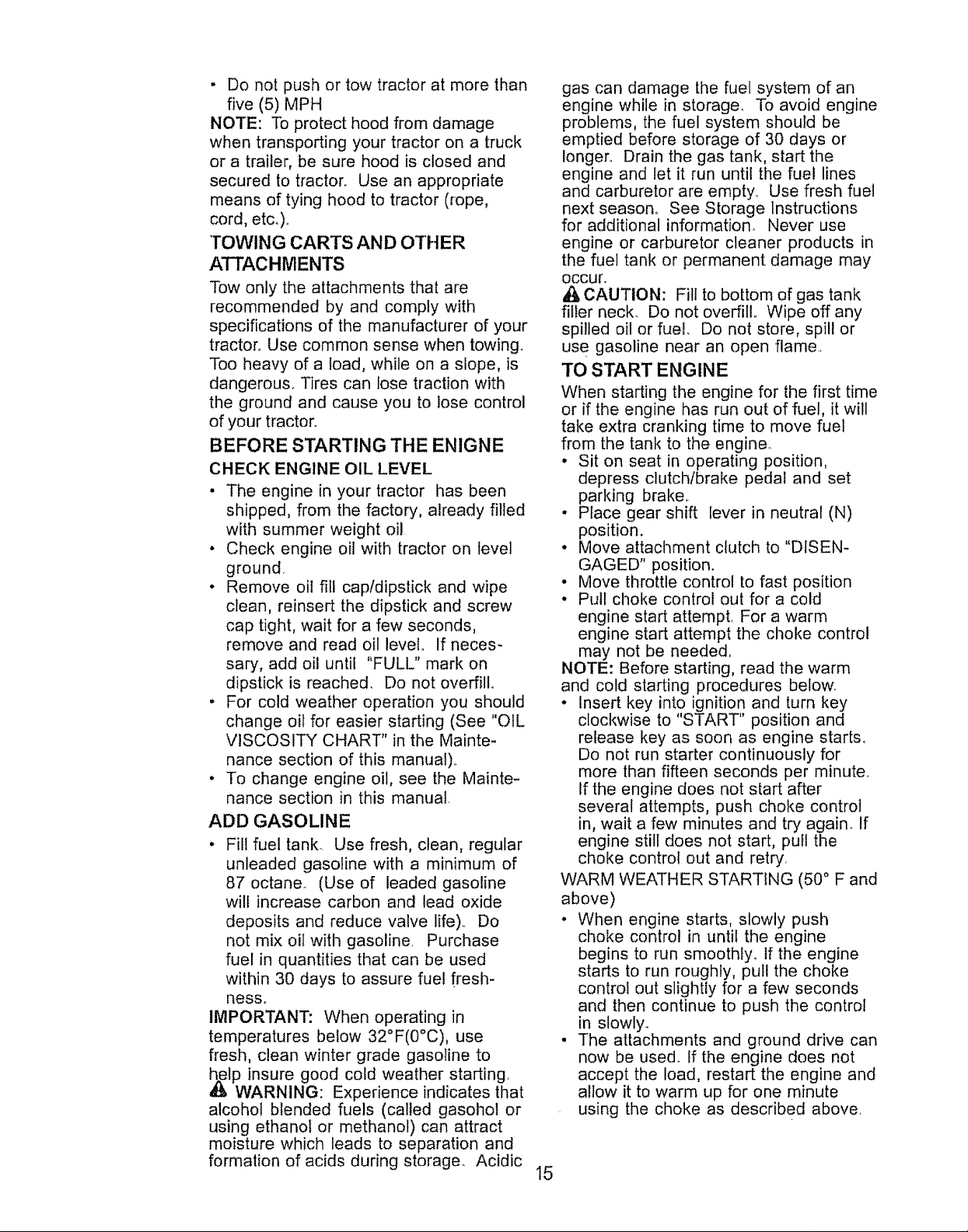
• When operating attachments, select a
ground speed that will suit the terrain
and give best performance of the
attachment being used.
f
r
MULCHING MOWING TIPS
IMPORTANT: For best performance,
keep mower housing free of built-up
grass and trash, Clean after each use,
• The special mulching blade will recut
the grass clippings many times and
reduce them in size so that as they fall
onto the lawn they will disperse into
the grass and not be noticed. Also, the
mulched grass will biodegrade quickly
to provide nutrients for the lawno
Always mulch with your highest
engine (blade) speed as this will
provide the best recurring action of the
blades°
• Avoid cutting your lawn when it is wet,,
Wet grass tends to form clumps and
interferes with the mulching action.
The best time to mow your lawn is the
early afternoon,, At this time the grass
has dried and the newly cut area will
not be exposed to the direct sun.
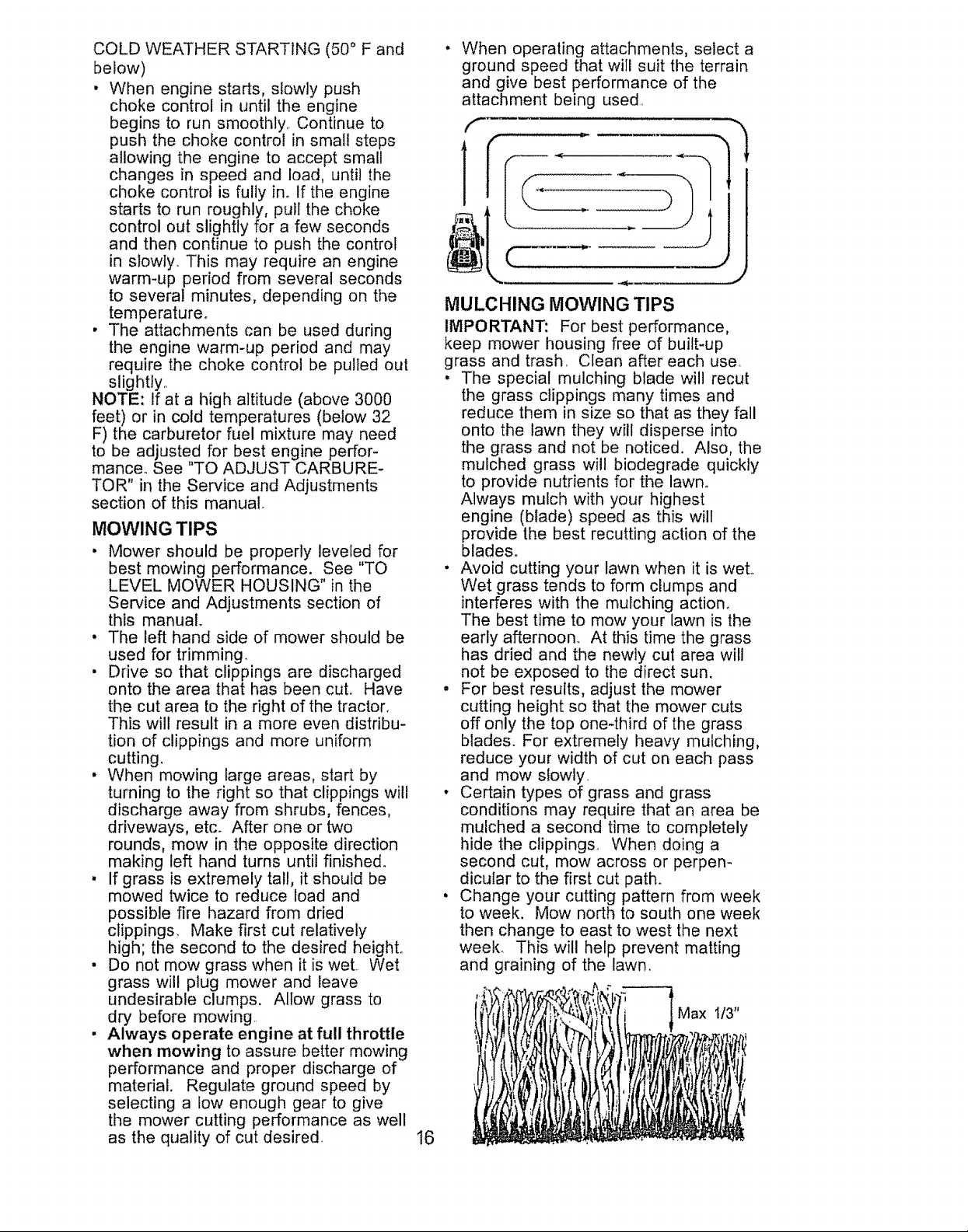
o For best results, adjust the mower
cutting height so that the mower cuts
off only the top one-third of the grass
blades. For extremely heavy mulching,
reduce your width of cut on each pass
and mow slowly.
• Certain types of grass and grass
conditions may require that an area be
mulched a second time to completely
hide the clippings. When doing a
second cut, mow across or perpen-
dicular to the first cut path.
• Change your cutting pattern from week
to week. Mow north to south one week
then change to east to west the next
week. This will help prevent matting
and graining of the lawn.
Max 1t3"
I6
Choc._rokeOperation _ V' i I
.CheckTl'eP'essu'e :V" _ I . . _
o.oo.o0oro,o. oooooooo. I I I I 1 Ii
T
Interlock Systems t,_
R
Check for LoOSe Fasteners ' V' _'_
A
_S._;p_;_R_ple_e_Mow_Bi"_e_...................... V', .........................................................
c
Lubrication Chart _,f _ ..........
Che_,Ba!ter','_Le'or................. V; . . .
o
CIean Battery and Terminals if
R
Check Transaxle Cooling
Adjust Blade Belt(s) Tension _'r,
Adjust Motlon Drive Belt(s) Tension _,_
I'1111IIIIIIII III IIIII I I I LI II I III I I II I L I
Check Engine Oil Level _#'
Change Engine Oil 1_._.3 V #'
Ciean Air Filler _#'2
E
N
Ciean Air Screen _"_
__inspec_Mui_er/spa,k Arrestor i !_
Replace0iiFilter(ifequipped) I I I_i=1 I I 1 1 i !
Rop_aoeSparkPI"g ...................................... _' V ...............
Replace Air F#ter Paper Cartridge _/'z
Replace Fuel Ftfter _'
1 - Chr_nge mete often when eperal{ng _Jnde_"a heavy load o_"In high ambient temper_l=._res
2 - Service more o_en when operating tn dirty or d*,ls|y cond_,ilan._
3 - If equipped wilh o_l rifler, change ott every 50 hours
4 - Replace blades more at:ten when mowing In sandy soil
GENERAL RECOMMENDATIONS
LUBRICATION CHART
The warranty on this tractor does not
cover items that have been subjected to
operator abuse or negligence. To
receive full value from the warranty,
operator must maintain tractor as
instructed in this manual.
_Front Wheel,-i! , {_Front Wheel
Some adjustments will need to be made
periodically to properly maintain your
tractor,
All adjustments in the Service and
Adjustments section of this manual
should be checked at least once each
season.
* Once a year you should replace the
spark plug, clean or replace air filter,
and check blades and belts for wear_
A new spark plug and clean air filter
assure proper air-fue! mixture and
help your engine run better and last
longer.
BEFORE EACH USE
. Check engine oil level.
. Check brake operation,
. Check tire pressure,
. Check operator presence and
interlock systems for proper operation.
• Check for loose fasteners.
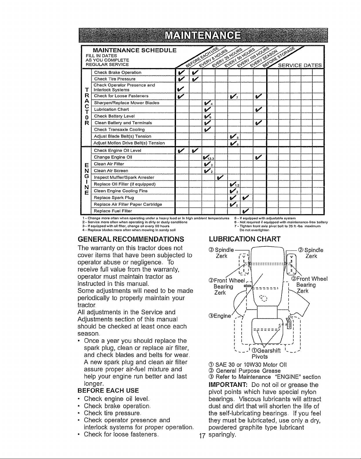
d) SAE 30 or t0W30 Motor OII
@ General Purpose Grease
(3.)Refer to Maintenance "ENGINE" section
IMPORTANT: Do not oil or grease the
pivot points which have special nylon
bearings,, Viscous lubricants wil! attract
dust and dirt that will shorten the life of
the self-lubricating bearings, If you feet
they must be lubricated, use only a dry,
powdered graphite type lubricant
sparingly,
17
Spindle -- r--------_, r--- _) Spindle
Zerk _-"__ II1_-_ Zerk
Bearing _V" j-i Bearing
Zerk /,,.._/I: _,,_= ==' ! _L"-_ rk
_5- I_ eq#ipped w{th adiuelab!e aystem
6 - Net reqidred it equipped wtlh mainlenmnce4ree battery
7 * Tlghlee front axle pivot bolt _o 35 _t.-lbs m_xlmum
DO not overllghlen
l "--r - - "_Z - - -- "r -# I
'- __Ge'arshift _.... -J
Pivots

TRACTOR
Always observe safety rules when
performing any maintenance..
BRAKE OPERATION
if tractor requires more than six (6) feet
stopping distance at high speed in
highest gear, then brake must be
adjustedo (See "TO ADJUST BRAKE" in
the Service and Adjustments section of
this manual),
TIRES
o Maintain proper air pressure in all tires
(See "PRODUCT SPECIFICATIONS"
section of this manual)
• Keep tires free of gasoline, oil, or
insect control chemicals which can
harm rubber,,
• Avoid stumps, stones, deep ruts, sharp
objects and other hazards that may
cause tire damage..
NOTE: To seal tire punctures and
prevent flat tires due to slow leaks, tire
sealant may be purchased from your
local parts dealer.. Tire sealant also
prevents tire dry rot and corrosion.
OPERATOR PRESENCE SYSTEM
Be sure operator presence and interlock
systems are working properly., if your
tractor does not function as described,
repair the problem immediately_
• The engine should not start unless the
clutch/brake pedal is fully depressed
and attachement clutch control is in
the disengaged position,.
• When the engine is running, any
attempt by the operator to leave the
seat without first setting the parking
brake should shut off the engine.
• When the engine is running and the
attachment clutch is engaged, any
attempt by the operator to leave the
seat should shut off the engine.
• The attachment clutch should never
operate unless the operator is in the
seat°
BLADE CARE
For best results mower blades must be
kept sharp. Replace bent or damaged
blades.
BLADE REMOVAL
• Raise mower to highest position to
allow access to blades..
• Remove hex bolt, lock washer and flat
washer securing blade.
• Install new or resharpened blade with
trailing edge up towards deck as
shown..
IMPORTANT: To ensure proper assem-
bly, center hole in blade must align with
star on mandrel assembly.
• Reassemble hex bolt, lock washer and
flat washer in exact order as shown.
• Tighten bolt securely (27_35 Ft. Lbs_
torque).
IMPORTANT: Blade bolt is Grade 8 heat
treated.
Trailing Edge Up
Blade Center
Flat Washer..
Lock Washer
Hex Bolt
*A Grade 8 heat treated bolt can be identified
by six lines on the bolt head,
TO SHARPEN BLADE
NOTE: We do not recommend sharpen-
ing blade - but if you do, be sure the
blade is balanced°
Care should be taken to keep the blade
balanced.. An unbalanced blade will
cause excessive vibration and eventual
damage to mower and engine_
. The blade can be sharpened with a
file or on a grinding wheel. Do not
attempt to sharpen while on the
mower.
- To check blade balance, you will need
a 5/8" diameter steel bolt, pin, or a
cone balancer. (When using a cone
balancer, follow the instructions
supplied with balancer 0
NOTE: Do not use a nail for balancing
blade. The lobes of the center hole may
appear to be centered, but are not.
. Slide blade on to an unthreaded
portion of the steel bolt or pin and hold
the bolt or pin parallel with the ground.
If blade is balanced, it should remain
in a horizonta! position. If either end of
the blade moves downward, sharpen
the heavy end until the blade is
balanced.
Mandrel Assembly
Hole
18
 Loading...