

Page 1

Owner's Manual
CRnFTSMnNo
16.0 HP
ELECTRIC START
42" MOWER
AUTOMATIC
LAWN TRACTOR
Model No.
917.270680
• Safety
• Assembly
• Operation
• Maintenance
• Repair Parts
dnfferently from previously built engines, Before you start the en-
This product has a low emission engine which operates
gine, read and understand this Owner's Manual.
CAUTION:
Read and follow all Safety
Rules and Instructions before
operating this equipment.
For answers to your questions
about this product, Call:
1-800-659-5917
Sears Craftsman Help Line
5 am- 5 pro, Mon - Sat
Sears, Roebuck and Co., Hoffman Estates, II 60179
Visit our Craftsman website:www.sears.com/craftsman
Page 2
Warranty...............................................2
SafetyRules.........................................3
ProductSpecifications..........................5
Assembly..............................................7
Operation............................................10
Maintenance.......................................17
MaintenanceSchedule......................17
ServiceandAdjustments....................21
Storage...............................................28
Troubleshooting.................................29
RepairParts........................................34
PartsOrdering.....................BackCover
LIMITEDTWOYEARWARRANTYONCRAFTSMANRIDINGEQUIPMENTPARTS
Fortwo(2)yearsfromthedateofpurchase,if thisCraftsmanRidingEquipmentis
maintained,lubricatedandtuned up accordingto the instructionsin the owner's
manual,Searswillrepairorreplace,freeofcharge,any partsfoundto bedefectivein
materialor workmanship.Warrantyserviceis availablefreeofchargeby takingyour
CraftsmanridingequipmenttoyournearestSearsServiceCenter. In-homewarranty
serviceisavailablebutatripchargewillapply.Thiswarrantyappliesonlywhilethis
productisinthe UnitedStates.
ThisWarrantydoesnotcover:
• Expendableitemswhichbecomewornduringnormaluse,suchas blades,spark
plugs,air cleaners,beltsandoilfilters.
• Tire replacementorrepaircausedby puncturesfromoutsideobjects,suchas nails,
thorns,stumps,or glass.
• Repairs necessary because of operator abuse, including but not limited to, damage
caused by towing objects beyond the capability of the riding equipment, impacting
objects that bend the frame or crankshaft, or over speeding the engine.
• Repairs necessary because of operator negligence, including but not limited to,
electrical and mechanical damage caused by improper storage, failure to use the
proper grade and amount of engine oil, failure to keep the deck clear of flammable
debris, or the failure to maintain the equipment according to the instructions
contained in the owner's manual.
• Engine (fuel system) cleaning or repairs caused by fuel determined to be contami-
nated or oxidized (stale). In general, fuel should be used within thirty (30) days of its
purchase date.
• Riding equipment used for commercial or rental purposes.
LIMITED 90 DAY WARRANTY ON BATTERY
For ninety (90) days from date of purchase, if any battery included with this riding
equipment proves defective in material or workmanship and our testing determines
the battery will not hold a charge, Sears will replace the battery at no charge. War-
ranty service is available free of charge by taking your Craftsman riding equipment to
your nearest Sears Service Center. In-home warranty service is available but a trip
charge will apply. This warranty applies only while this product is in the United States.
To locate the nearest sears service center or to schedule in-home warranty service,
simply contact sears at 1-800-4-my-home
This Warranty gives you specific legal rights, and you may also have other rights
which may vary from state to state.
Sears, Roebuck and Co., D/817 WA, Hoffman Estates, IL 60179
2
Page 3
IMPORTANT: This cutting machine is
capable of amputating hands and feet
and throwing objects. Failure to observe
the following safety instructions could
result in serious injury or death.
GENERAL OPERATION
• Read, understand, and follow all
instructions in the manual and on the
machine before starting.
• Only allow responsible adults, who are
familiar with the instructions, to operate
the machine.
• Clear the area of objects such as rocks,
toys, wire, etc., which could be picked
up and thrown by the blade.
• Be sure the area is clear of other
people before mowing. Stop machine if
anyone enters the area.
• Never carry passengers.
• Do not mow in reverse unless absolute-
ly necessary. Always look down and
behind before and while backing.
• Be aware of the mower discharge
direction and do not point it at anyone.
Do not operate the mower without
either the entire grass catcher or the
guard in place.
• Slow down before turning.
• Never leave a running machine
unattended. Always turn off blades, set
parking brake, stop engine, and remove
keys before dismounting.
• Turn off blades when not mowing.
• Stop engine before removing grass
catcher or unclogging chute.
• Mow only in daylight or good artificial
light.
• Do not operate the machine while
under the influence of alcohol or drugs.
• Watch for traffic when operating near or
crossing roadways.
• Use extra care when loading or
unloading the machine into a trailer or
truck.
• Data indicates that operators, age 60
years and above, are involved in a
large percentage of riding mower-
related injuries. These operators should
evatuate their ability to operate the
riding mower safely enough to protect
themselves and others from serious
injury.
SLOPE OPERATION
Slopes are a major factor related to loss-
of-control and tipover accidents, which
can result in severe injury or death. All
slopes require extra caution. If you canno_
back up the slope or if you feel uneasy or
it, do not mow it.
DO;
• Mow up and down slopes, not across.
• Remove obstacles such as rocks, tree
limbs, etc.
• Watch for holes, ruts, or bumps. Uneve
terrain could overturn the machine. Tal
grass can hide obstacles.
• Use slow speed. Choose a low gear sc
that you will not have to stop or shift
while on the slope.
• Follow the manufacturer's recommen-
dations for wheel weights or counter-
weights to improve stability.
• Use extra care with grass catchers or
other attachments. These can change
the stability of the machine.
• Keep all movement on the slopes slow
and gradual. Do not make sudden
changes in speed or direction.
• Avoid starting or stopping on a slope. If
tires lose traction, disengage the blade
and proceed slowly straight down the
slope.
DO NOT:
• Do not turn on slopes unless neces-
sary, and then, turn stowly and gradual-
ly downhill, if possible.
• Do not mow near drop-offs, ditches, or
embankments. The mower could
suddenly turn over if a wheel is over the
edge of a cliff or ditch, or if an edge
caves in.
• Do not mow on wet grass. Reduced
traction could cause sliding.
• Do not try to stabilize the machine by
putting your foot on the ground.
• Do not use grass catcher on steep
slopes.
CHILDREN
Tragic accidents can occur if the operator
is not alert to the presence of children.
Children are often attracted to the
machine and the mowing activity. Never
assume that children will remain where
you last saw them.
• Keep children out of the mowing area
and under the watchful care of another
responsible adult.
• Be alert and turn machine off if children
enter the area.
3
Page 4
• Before and when backing, look behind
and down for small children.
• Never carry children. They may fall off
and be seriously injured or interfere
with safe machine operation.
• Never allow children to operate the
machine.
• Use extra care when approaching blind
corners, shrubs, trees, or other objects
that may obscure vision.
SERVICE
• Use extra care in handling gasoline
and other fuels. They are flammable
and vapors are explosive.
Use only an approved container.
Never remove gas cap or add fuel
with the engine running. Allow
engine to cool before refueling. Do
not smoke.
Never refuel the machine indoors.
Never store the machine or fue_
container inside where there is an
open flame, such as a water heater.
• Never run a machine inside a closed
area.
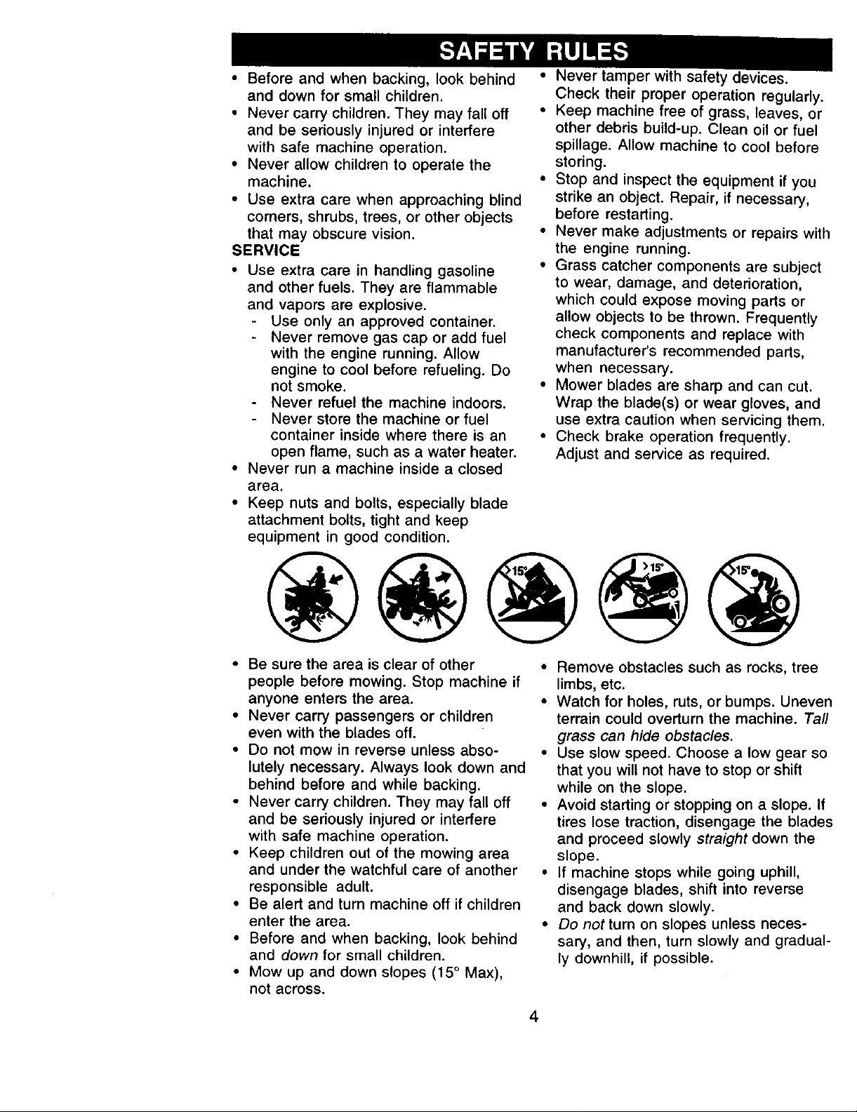
• Keep nuts and bolts, especially blade
attachment bolts, tight and keep
equipment in good condition.
• Never tamper with safety devices.
Check their proper operation regularly.
• Keep machine free of grass, leaves, or
other debris build-up. Clean oil or fuel
spillage. Allow machine to cool before
storing.
• Stop and inspect the equipment if you
strike an object. Repair, if necessary,
before restarting.
• Never make adjustments or repairs witf
the engine running.
• Grass catcher components are subject
to wear, damage, and deterioration,
which could expose moving parts or
allow objects to be thrown. Frequently
check components and replace with
manufacturer's recommended parts,
when necessary.
• Mower blades are sharp and can cut.
Wrap the blade(s) or wear gloves, and
use extra caution when servicing them.
• Check brake operation frequently.
Adjust and service as required.
• Be sure the area is clear of other
people before mowing. Stop machine if
anyone enters the area.
• Never carry passengers or children
even with the blades off.
• Do not mow in reverse unless abso-
lutely necessary. Always look down and
behind before and while backing.
• Never carry children. They may fall off
and be seriously injured or interfere
with safe machine operation.
• Keep children out of the mowing area
and under the watchful care of another
responsible adult.
• Be alert and turn machine off if children
enter the area.
• Before and when backing, look behind
and down for small children.
• Mow up and down slopes (15 ° Max),
not across.
• Remove obstacles such as rocks, tree
limbs, etc.
• Watch for holes, ruts, or bumps. Unevel
terrain could overturn the machine. Tal,
grass can hide obstacles.
• Use slow speed. Choose a low gear sc
that you will not have to stop or shift
while on the slope.
• Avoid starting or stopping on a slope. If
tires lose traction, disengage the blade
and proceed slowly straight down the
slope.
• If machine stops while going uphill,
disengage blades, shift into reverse
and back down slowly.
• Do not turn on slopes unless neces-
sary, and then, turn slowly and gradual.
ly downhill, if possible.
4
Page 5
,ALook for this symbol to point out
important safety precautions. It means
CAUTIONt!t BECOME AWARE!!! YOUR
_FETY IS INVOLVED.
CAUTION= In order to prevent
accidental starting when setting up,
transporting, adjusting or making repairs
always disconnect spark plug wire and
place wire where it cannot contact spark
CAUTION: Do not coast down a hill in
neutral, you may lose control of the
tractor.
_L, CAUTION: Tow only the attachments
that are recommended by and comply
with specifications of the manufacturer o=
your tractor. Use common sense when
towing. Operate only at the lowest
possible speed when on a slope. Too
heavy of a load, while on a slope, is
dangerous. Tires can lose traction with tl
ground and cause you to lose control of
_luWAr tractOr.
RNING: The engine exhaust from
this product contains chemicals known t(
the State of California to cause cancer,
birth defects, or other reproductive harm.
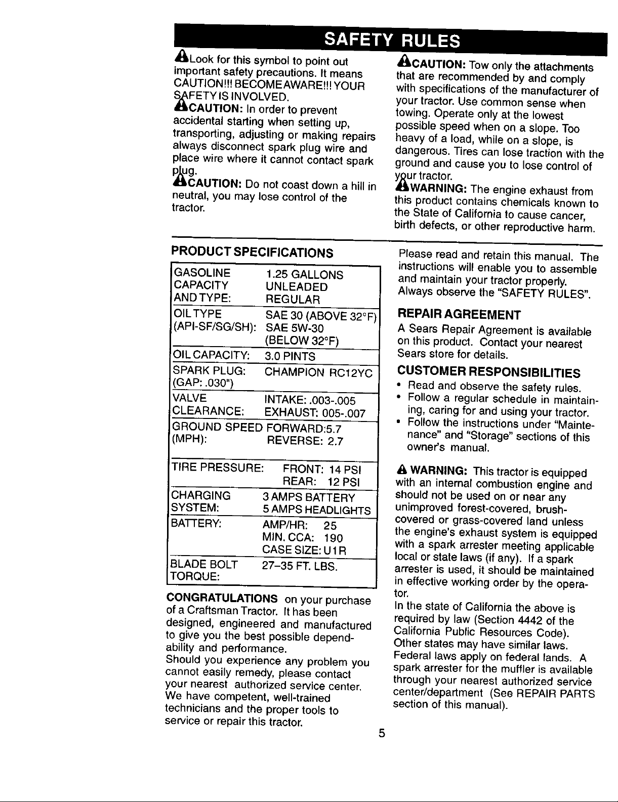
PRODUCT SPECIFICATIONS
GASOLINE 1.25 GALLONS
CAPACITY UNLEADED
_NDTYPE: REGULAR
OILTYPE SAE 30 (ABOVE 32°F
(API-SF/SG/SH): SAE 5W-30
(BELOW 32°F)
OIL CAPACITY: 3.0 PINTS
SPARK PLUG: CHAMPION RC12YC
GAP: .030")
VALVE INTAKE: .003-.005
CLEARANCE: EXHAUST: 005-.007
GROUND SPEED FORWARD:5.7
(MPH): REVERSE: 2.7
TIRE PRESSURE: FRONT: 14 PSI
REAR: 12 PSI
CHARGING 3AMPS BATTERY
SYSTEM: 5 AMPS HEADLIGHTS
BA'I-rERY: AMP/HR: 25
MIN. CCA: 190
CASE SIZE: U1R
BLADE BOLT 27-35 FT. LBS.
TORQUE:
CONGRATULATIONS on your purchase
of a Craftsman Tractor. It has been
designed, engineered and manufactured
to give you the best possible depend-
ability and performance.
Should you experience any problem you
cannot easily remedy, please contact
your nearest authorized service center.
We have competent, well-trained
technicians and the proper tools to
service or repair this tractor.
Please read and retain this manual. Th_
instructions will enable you to assemble
and maintain your tractor properly.
Always observe the "SAFETY RULES".
REPAIR AGREEMENT
A Sears Repair Agreement is available
on this product. Contact your nearest
Sears store for details.
CUSTOMER RESPONSIBILITIES
• Read and observe the safety rules.
• Follow a regular schedule in maintain.
ing, caring for and using your tractor.
• Follow the instructions under "Mainte-
nance" and "Storage" sections of this
owner's manual.
WARNING= This tractor is equipped
with an internal combustion engine and
should not be used on or near any
unimproved forest-covered, brush-
covered or grass-covered land unless
the engine's exhaust system is equippe_
with a spark arrester meeting applicable
local or state laws (if any). If a spark
arrester is used, it should be maintained
in effective working order by the opera-
tor.
In the state of California the above is
required by law (Section 4442 of the
California Public Resources Code).
Other states may have similar laws.
Federal laws apply on federal lands. A
spark arrester for the muffler is available
through your nearest authorized service
center/department (See REPAIR PARTS
section of this manual).
5
Page 6
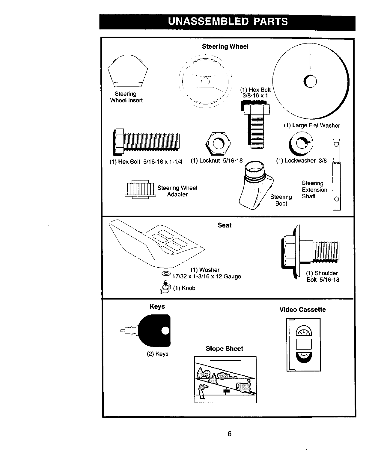
Steering Wheel
//,S_', \
Steering
Wheel Insert
(1) Hex Bolt 5/16-18 x 1-1/4
,_ Steering Wheel
Adapter
(1) Locknut 5/16-18
Seat
(1) Hex Bolt
3/8-16 x 1
(1) Large Flat Washer
(1) Lockwasher 3/8 ___
Steering
Extension
Shaft
Boot
C
_(1) Knob
Keys
(2) Keys
(1) Washer
17/32 x 1-3/16 x 12 Gauge
Slope Sheet
6
(1) Shoulder
Bolt 5/16-18
Video Cassette
Page 7
Your new tractor has been assembled at the factory with exception of those parts left
unassembled for shipping purposes. To ensure safe and proper operation of your
tractor all parts and hardware you assemble must be tightened securely. Use the
correct tools as necessary to insure proper tightness. Review the video cassette befo
you begin.
TOOLS REQUIRED FOR
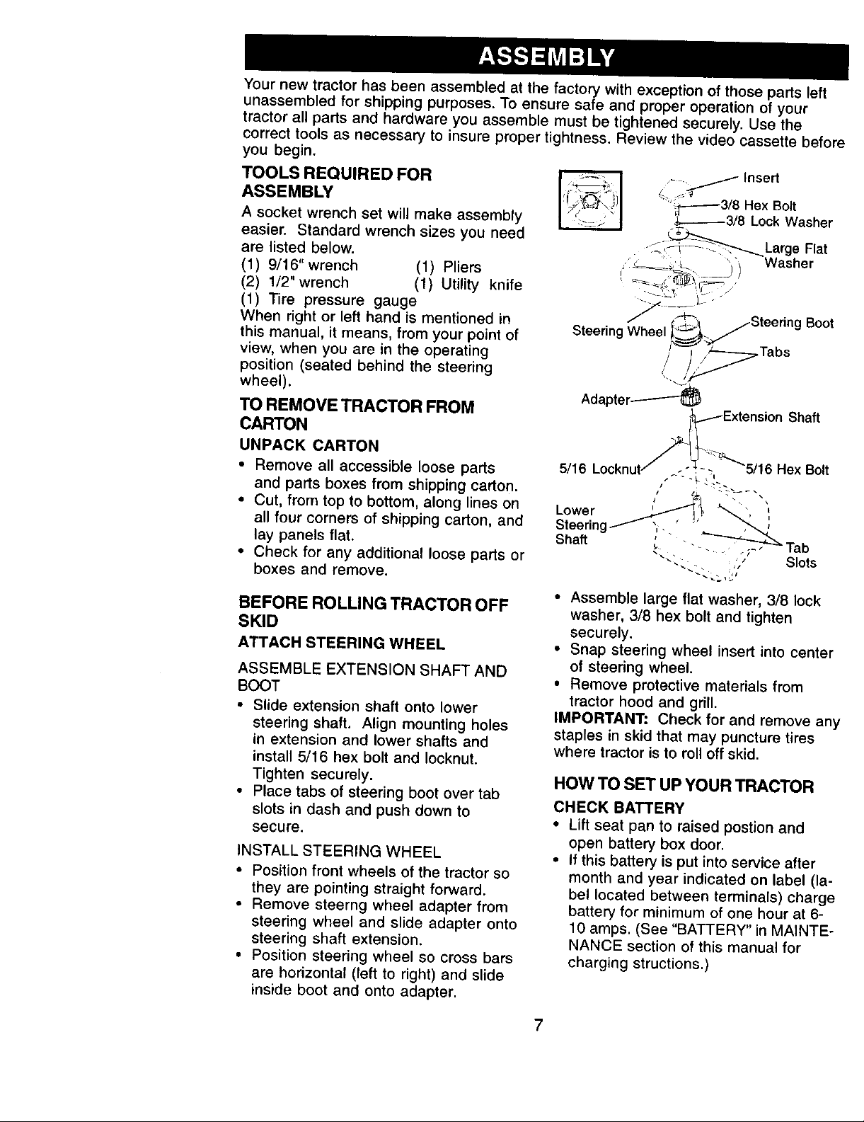
.__/ Insert
ASSEMBLY
A socket wrench set will make assembly
easier. Standard wrench sizes you need
are listed below.
(1) 9/16"wrench (1) Pliers
(2) 1/2" wrench (1) Utility knife
(1) Tire pressure gauge
When right or left hand is mentioned in
this manual, it means, from your point of
view, when you are in the operating
position (seated behind the steering
wheel).
TO REMOVE TRACTOR FROM
Steering Wheel
AdapteP_-_
• ;T-------3/8 Hex Bolt
_,.--------3/8 Lock Washer
-__"_L
-- arge Fat
' Washer
Boot
,Tabs
Shaft
CARTON
UNPACK CARTON
• Remove all accessible loose parts
and parts boxes from shipping carton.
• Cut, from top to bottom, along lines on
all four corners of shipping carton, and
lay panels flat.
• Check for any additional loose parts or
boxes and remove.
BEFORE ROLLING TRACTOR OFF
SKID
ATTACH STEERING WHEEL
ASSEMBLE EXTENSION SHAFT AND
BOOT
• Slide extension shaft onto lower
steering shaft. Align mounting holes
in extension and lower shafts and
install 5/16 hex bolt and Iocknut.
Tighten securely.
• Place tabs of steering boot over tab
slots in dash and push down to
secure.
INSTALL STEERING WHEEL
• Position front wheels of the tractor so
they are pointing straight forward.
• Remove steerng wheel adapter from
steering wheel and slide adapter onto
steering shaft extension.
• Position steering wheel so cross bars
are horizontal (left to right) and slide
inside boot and onto adapter.
• Assemble large flat washer, 3/8 lock
washer, 3/8 hex bolt and tighten
securely.
• Snap steering wheel insert into center
of steering wheel.
• Remove protective materials from
tractor hood and grill.
IMPORTANT: Check for and remove an
staples in skid that may puncture tires
where tractor is to roll off skid.
HOW TO SET UP YOUR TRACTOR
CHECK BATTERY
• Lift seat pan to raised postion and
open battery box door.
• If this battery is put into service after
month and year indicated on label (la-
bel located between terminals) charge
battery for minimum of one hour at 6-
10 amps. (See "BATTERY" in MAINTE-
NANCE section of this manual for
charging structions.)
Page 8
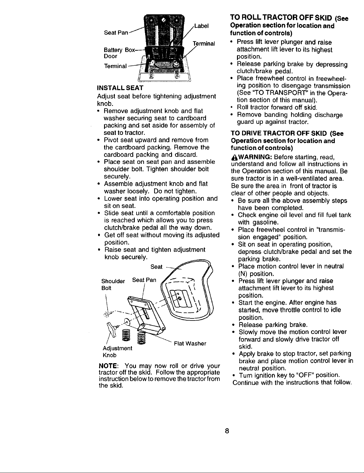
Label
Terminal
Ba_er
Door
INSTALL SEAT
Adjust seat before tightening adjustment
knob.
• Remove adjustment knob and flat
washer securing seat to cardboard
packing and set aside for assembly of
seat to tractor.
• Pivot seat upward and remove from
the cardboard packing. Remove the
cardboard packing and discard.
• Place seat on seat pan and assemble
shoulder bolt. Tighten shoulder bolt
securely.
• Assemble adjustment knob and flat
washer loosely. Do not tighten.
• Lower seat into operating position and
sit on seat.
• Slide seat until a comfortable position
is reached which allows you to press
clutch/brake pedal all the way down.
• Get off seat without moving its adjusted
position.
• Raise seat and tighten adjustment
knob securely.
Seat _
Shouder SeatPan ,_._-_-_ {(t
Adjustment
Knob
NOTE: You may now roll or drive your
tractor off the skid. Follow the appropriate
instruction below to remove the tractor from
the skid.
TO ROLL TRACTOR OFF SKID (See
Operation section for location and
function of controls)
• Press lift lever plunger and raise
attachment lift lever to its highest
position.
• Release parking brake by depressing
clutch/brake pedal.
• Place freewheel control in freewheel-
ing position to disengage transmission
(See "TO TRANSPORT" in the Opera-
tion section of this manual).
• Roll tractor forward off skid.
• Remove banding holding discharge
guard up against tractor.
TO DRIVE TRACTOR OFF SKID (See
Operation section for location and
function of controls)
_I,WARNING: Before starting, read,
understand and follow all instructions in
the Operation section of this manual. Be
sure tractor is in a well-ventilated area.
Be sure the area in front of tractor is
clear of other people and objects.
• Be sure all the above assembly steps
have been completed.
• Check engine oil level and fill fuel tank
with gasoline.
• Place freewheel control in "transmis-
sion engaged" position.
• Sit on seat in operating position,
depress clutch/brake pedal and set the
parking brake.
• Place motion control lever in neutral
(N) position.
• Press lift lever plunger and raise
attachment lift lever to its highest
position.
• Start the engine. After engine has
started, move throttle control to idle
position.
• Release parking brake.
• Slowly move the motion control lever
forward and slowly drive tractor off
skid.
• Apply brake to stop tractor, set parking
brake and place motion control lever in
neutral position.
• Turn ignition key to "OFF" position.
Continue with the instructions that follow.
8
Page 9
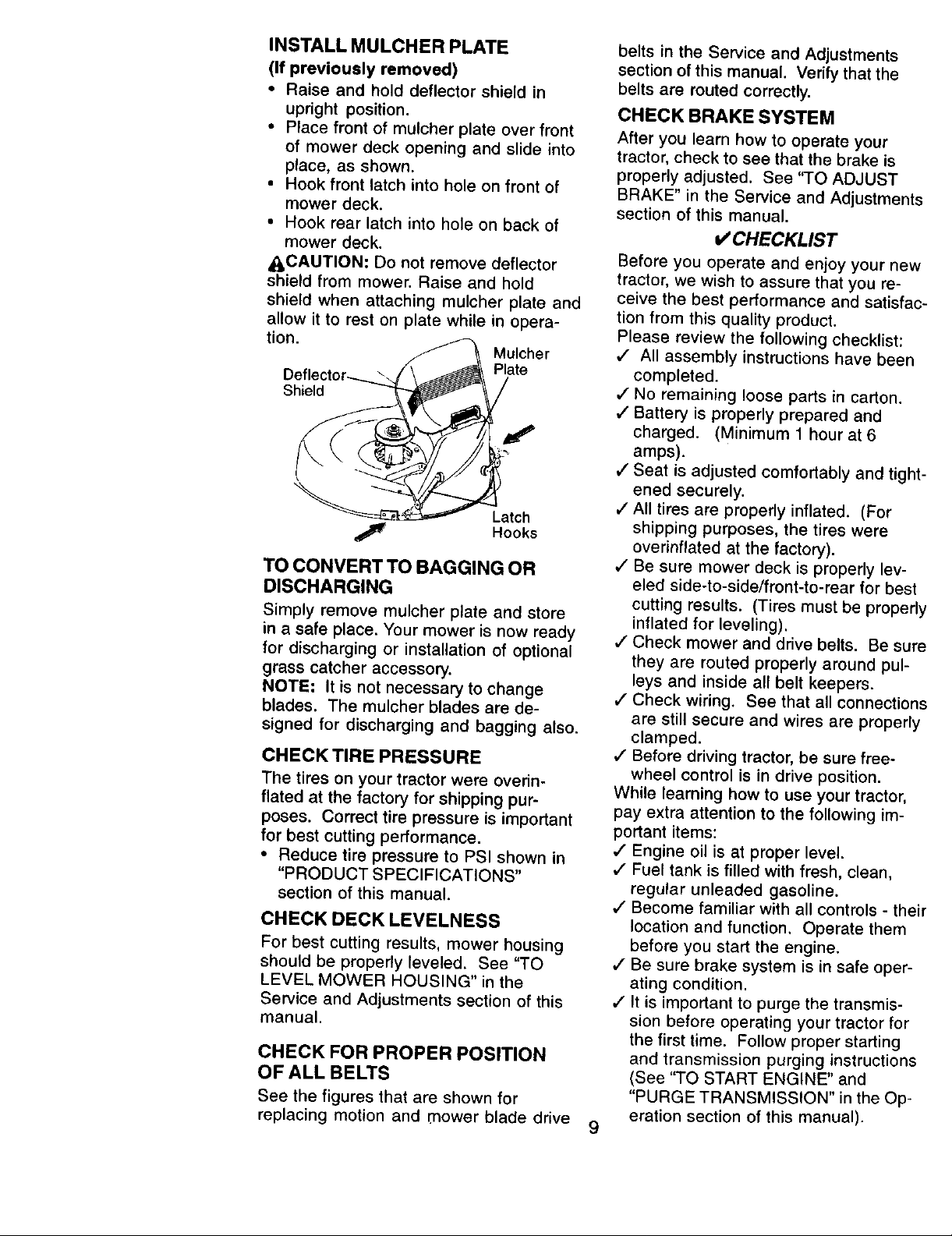
INSTALL MULCHER PLATE
(If previously removed)
• Raise and hold deflector shield in
upright position.
• Place front of mulcher plate over front
of mower deck opening and slide into
place, as shown.
• Hook front latch into hole on front of
mower deck.
• Hook rear latch into hole on back of
mower deck.
_CAUTION: Do not remove deflector
shield from mower. Raise and hold
shield when attaching mulcher plate and
allow it to rest on plate while in opera-
tion.
Mulcher
Plate
Shield
Latch
Hooks
TO CONVERT TO BAGGING OR
DISCHARGING
Simply remove mulcher plate and store
in a safe place. Your mower is now ready
for discharging or installation of optional
grass catcher accessory.
NOTE: It is not necessary to change
blades. The mulcher blades are de-
signed for discharging and bagging also.
CHECK TIRE PRESSURE
The tires on your tractor were overin-
flated at the factory for shipping pur-
poses. Correct tire pressure is important
for best cutting performance.
• Reduce tire pressure to PSI shown in
"PRODUCT SPECIFICATIONS"
section of this manual.
CHECK DECK LEVELNESS
For best cutting results, mower housing
should be properly leveled. See "TO
LEVEL MOWER HOUSING" in the
Service and Adjustments section of this
manual.
CHECK FOR PROPER POSITION
OF ALL BELTS
See the figures that are shown for
replacing motion and mower blade drive
belts in the Service and Adjustments
section of this manual. Verify that the
belts are routed correctly.
CHECK BRAKE SYSTEM
After you learn how to operate your
tractor, check to see that the brake is
properly adjusted. See "TO ADJUST
BRAKE" in the Service and Adjustment_
section of this manual.
V'CHECKL IS T
Before you operate and enjoy your new
tractor, we wish to assure that you re-
ceive the best performance and satisfac
tion from this quality product.
Please review the following checklist:
,/ All assembly instructions have been
completed.
J No remaining loose parts in carton.
,/Battery is properly prepared and
charged. (Minimum 1 hour at 6
amps).
,/Seat is adjusted comfortably and tighl
ened securely.
,/All tires are properly inflated. (For
shipping purposes, the tires were
overinflated at the factory).
,/Be sure mower deck is properly lev-
eled side-to-side/front-to-rear for best
cutting results. (Tires must be properl
inflated for leveling).
,/Check mower and drive belts. Be sun
they are routed properly around pul-
leys and inside all belt keepers.
,/Check wiring. See that all connection
are still secure and wires are properly
clamped.
4" Before driving tractor, be sure free-
wheel control is in drive position.
While learning how to use your tractor,
pay extra attention to the following im-
portant items:
_" Engine oil is at proper level.
,/Fuel tank is filled with fresh, clean,
regular unleaded gasoline.
,/Become familiar with all controls - the
location and function. Operate them
before you start the engine.
,/Be sure brake system is in safe oper-
ating condition.
,/It is important to purge the transmis-
sion before operating your tractor for
the first time. Follow proper starting
and transmission purging instructions
(See "TO START ENGINE" and
"PURGE TRANSMISSION" in the Op-
eration section of this manual).
9
Page 10
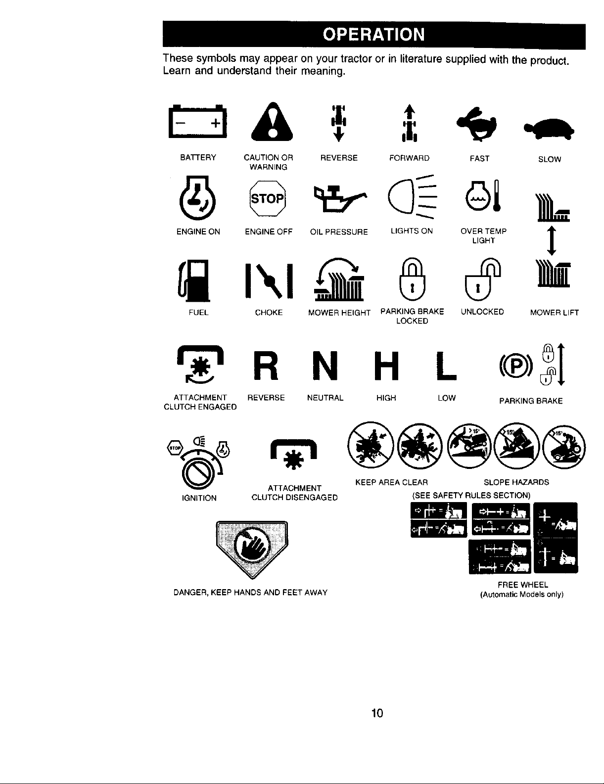
These symbols may appear on your tractor or in literature supplied with the product.
Learn and understand their meaning.
BA_-ERY CAUTION OR REVERSE FORWARD FAST SLOW
ENGINE ON ENGINE OFF OIL PRESSURE LIGHTS ON OVER TEMP
FUEL CHOKE MOWER HEIGHT PARKING BRAKE UNLOCKED MOWER LIFT
WARNING
LIGHT
LOCKED
R N H L
ATTACHMENT REVERSE NEUTRAL HIGH LOW PARKING BRAKE
CLUTCH ENGAGED
1
ATTACHMENT KEEP AREA CLEAR SLOPE HAZARDS
IGNITION CLUTCH DISENGAGED (SEE SAFETY RULES SECTION)
DANGER, KEEP HANDS AND FEET AWAY
FREE WHEEL
(Automatic Models only)
10
Page 11
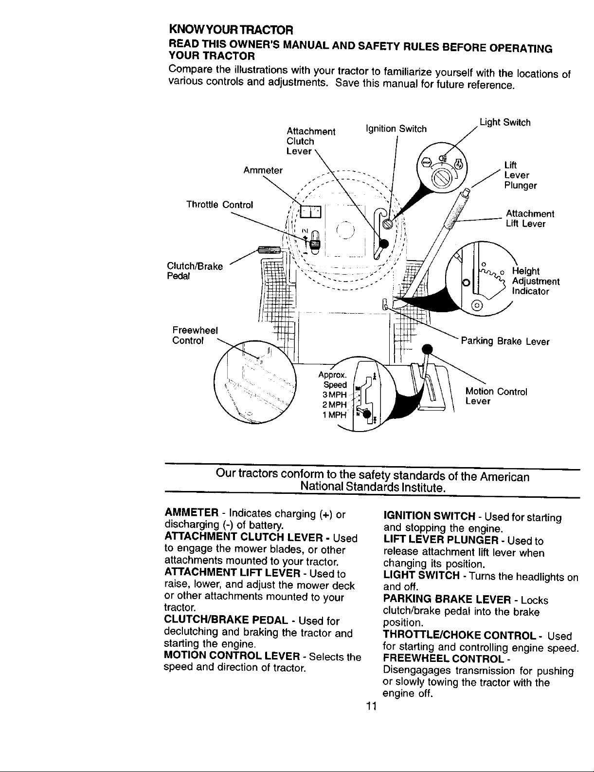
KNOW YOUR TRACTOR
READ THIS OWNER'S MANUAL AND SAFETY RULES BEFORE OPERATING
YOUR TRACTOR
Compare the illustrations with your tractor to familiarize yourself with the locations of
various controls and adjustments. Save this manual for future reference.
Attachment Ignition Switch
Light Switch
Clutch
Ammeter / Lever
Plunger
Throttle Control
Attachment
Lift Lever
Clutch/Brake " , , ' He
..... ight
Pedal -. "- ...... ,- Adjustment
- - ..... Indicator
Freewheel
Control
Approx.
Parking Brake Lever
• Speed _ Motion Controt
3MPH Lever
1MPH i
Our tractors conform to the safety standards of the American
National Standards Institute.
AMMETER - Indicates charging (+) or
discharging (-) of battery.
ATTACHMENT CLUTCH LEVER - Used
to engage the mower blades, or other
attachments mounted to your tractor.
ATTACHMENT LIFT LEVER - Used to
raise, lower, and adjust the mower deck
or other attachments mounted to your
tractor.
CLUTCH/BRAKE PEDAL - Used for
declutching and braking the tractor and
starting the engine.
MOTION CONTROL LEVER - Selects the
speed and direction of tractor.
i
IGNITION SWITCH - Used for starting
and stopping the engine.
LIFT LEVER PLUNGER - Used to
release attachment lift lever when
changing its position.
LIGHT SWITCH - Turns the headlights o
and off.
PARKING BRAKE LEVER - Locks
clutch/brake pedal into the brake
position.
THROTTLE/CHOKE CONTROL- Used
for starting and controlling engine speec
FREEWHEEL CONTROL -
Disengagages transmission for pushing
or slowly towing the tractor with the
engine off.
11
Page 12
The operation of any tractor can result in foreign objects thrown into
the eyes, which can result in severe eye damage. Always wear safety
glasses or eye shields while operating your tractor or performing any
adjustments or repairs. We recommend a wide vision safety mask
over spectacles or standard safety glasses.
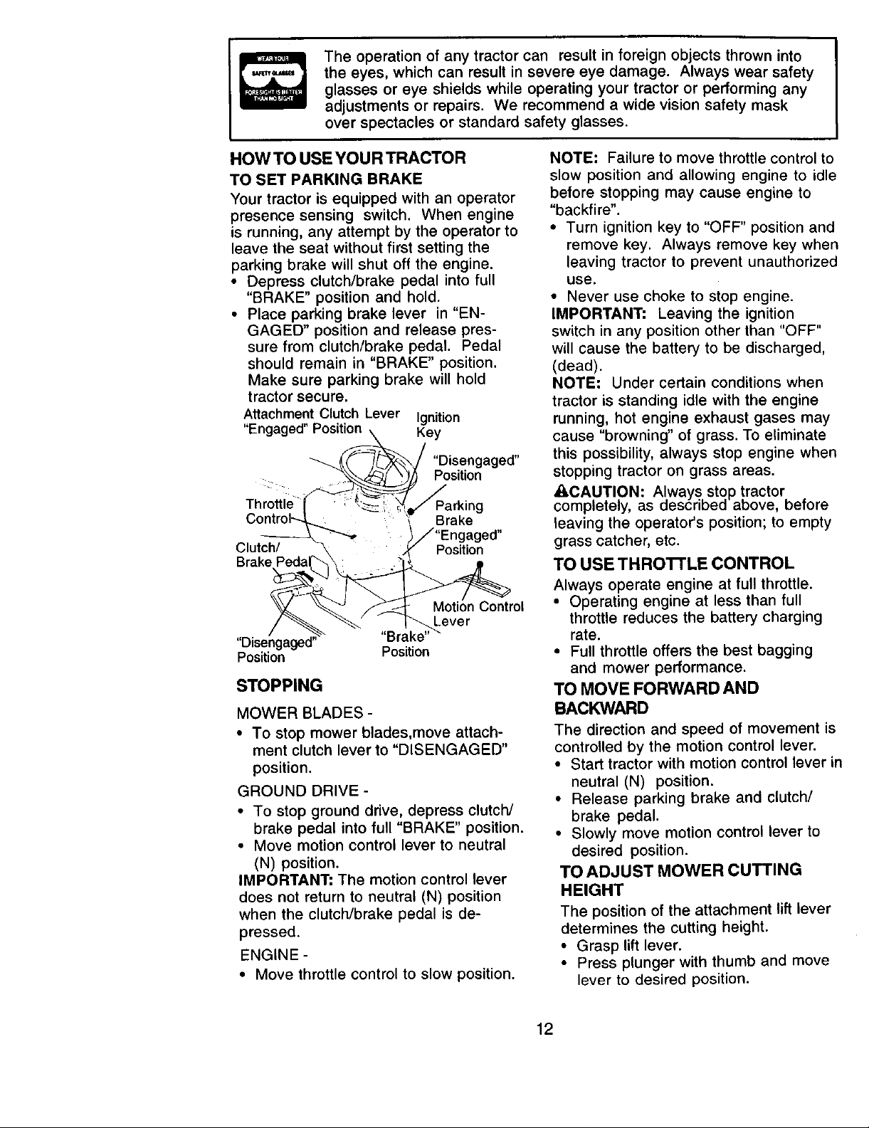
HOWTO USE YOUR TRACTOR
TO SET PARKING BRAKE
Your tractor is equipped with an operator
presence sensing switch. When engine
is running, any attempt by the operator to
leave the seat without first setting the
parking brake will shut off the engine.
• Depress clutch/brake pedal into full
"BRAKE" position and hold.
• Place parking brake lever in "EN-
GAGED" position and release pres-
sure from clutch/brake pedal. Pedal
should remain in "BRAKE" position.
Make sure parking brake will hold
tractor secure.
Attachment Clutch Lever Ignition
"Engaged" Position Key
"Disengaged"
Position
Throttle _
Clutch/ Position
"Disengaged" "Brake"_
Position Position
STOPPING
MOWER BLADES -
• To stop mower blades,move attach-
ment clutch lever to "DISENGAGED"
position.
GROUND DRIVE -
• To stop ground drive, depress clutch/
brake pedal into full "BRAKE" position.
• Move motion control lever to neutral
(N) position.
IMPORTANT: The motion control lever
does not return to neutral (N) position
when the clutch/brake pedal is de-
pressed.
ENGINE -
• Move throttle control to slow position.
g
Brake
Motion Control
Lever
NOTE: Failure to move throttle control to
slow position and allowing engine to idle
before stopping may cause engine to
"backfire".
• Turn ignition key to "OFF" position and
remove key. Always remove key when
leaving tractor to prevent unauthorized
use.
• Never use choke to stop engine.
IMPORTANT: Leaving the ignition
switch in any position other than "OFF"
will cause the battery to be discharged,
(dead).
NOTE: Under certain conditions when
tractor is standing idle with the engine
running, hot engine exhaust gases may
cause "browning" of grass. To eliminate
this possibility, always stop engine when
stopping tractor on grass areas.
_,CAUTION: AI.ways, stop tractor .
completeJy, as oescriDea aoove, berore
leaving the operator's position; to empty
grass catcher, etc.
TO USE THRO'I'rLE CONTROL
Always operate engine at full throttle.
• Operating engine at less than full
throttle reduces the battery charging
rate.
• Full throttle offers the best bagging
and mower performance.
TO MOVE FORWARD AND
BACKWARD
The direction and speed of movement is
controlled by the motion control lever.
• Start tractor with motion control lever in
neutral (N) position.
• Release parking brake and clutch/
brake pedal.
• Slowly move motion control lever to
desired position.
TO ADJUST MOWER CUTTING
HEIGHT
The position of the attachment lift lever
determines the cutting height.
• Grasp lift lever.
• Press plunger with thumb and move
lever to desired position.
12
Page 13
The cutting height range is approxi-
mately 1-1/2 to 4". The heights are
measured from the ground to the blade
tip with the engine not running. These
heights are approximate and may vary
depending upon soil conditions, height
of grass and types of grass being
mowed.
• The average lawn should be cut to
approximately 2-1/2 inches during the
cool season and to over 3 inches
during hot months. For healthier and
better looking lawns, mow often and
after moderate growth.
• For best cutting performance, grass
over 6 inches in height should be
mowed twice. Make the first cut
relatively high; the second to desired
height.
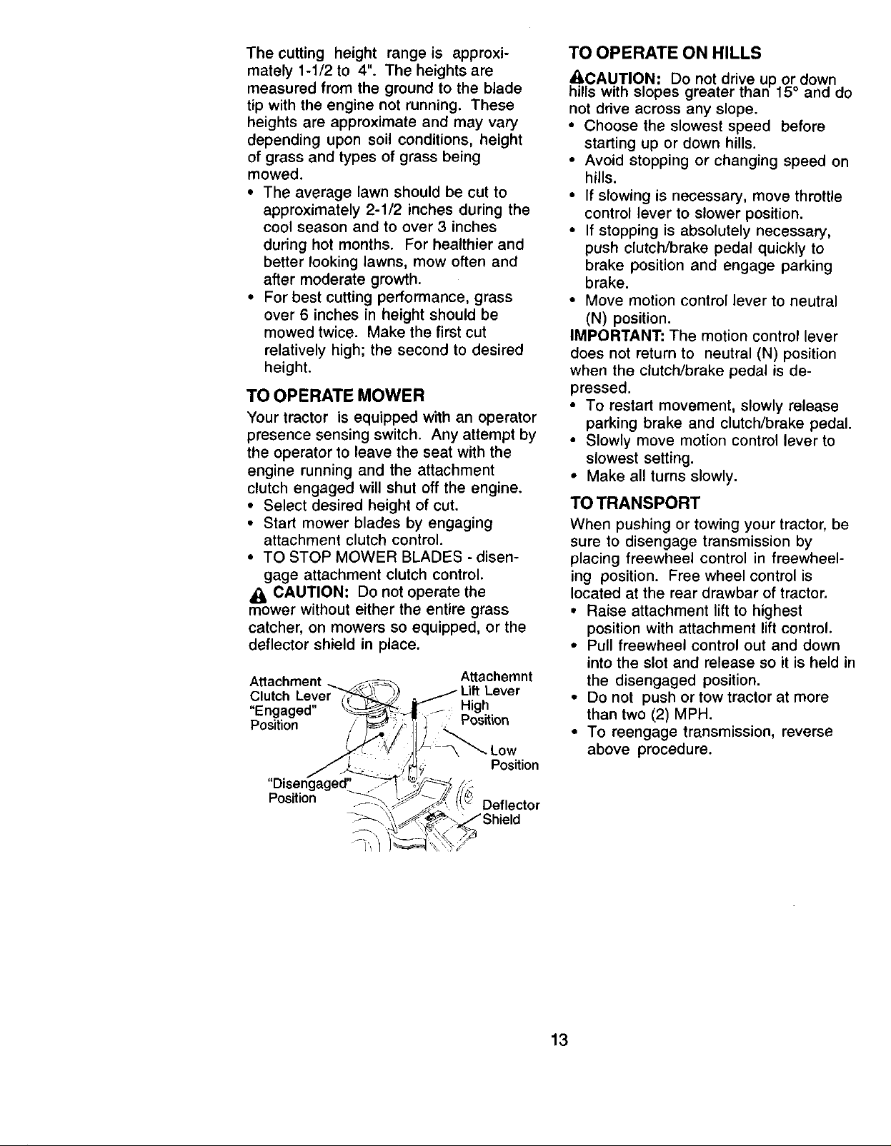
TO OPERATE MOWER
Your tractor is equipped with an operator
presence sensing switch. Any attempt by
the operator to leave the seat with the
engine running and the attachment
clutch engaged will shut off the engine.
• Select desired height of cut.
• Start mower blades by engaging
attachment clutch control.
• TO STOP MOWER BLADES - disen-
gage attachment clutch control.
CAUTION: Do not operate the
mower without either the entire grass
catcher, on mowers so equipped, or the
deflector shield in place.
Attachment Attachemnt
Clutch Lift Lever
"Engaged" High
Position / Position
Position
"Oisen_aged_
Position Deflector
TO OPERATE ON HILLS
A, CAUTION: Do not drive up or down
hills with slopes greater than 15° and do
not drive across any slope.
• Choose the slowest speed before
starting up or down hills.
• Avoid stopping or changing speed on
hills.
• If slowing is necessary, move throttle
control lever to slower position.
• If stopping is absolutely necessary,
push clutch/brake pedal quickly to
brake position and engage parking
brake.
• Move motion control lever to neutral
(N) position.
IMPORTANT: The motion control lever
does not return to neutral (N) position
when the clutch/brake pedal is de-
pressed.
• To restart movement, slowly release
parking brake and clutch/brake pedal.
• Slowly move motion control lever to
slowest setting.
• Make all turns slowly.
TOTRANSPORT
When pushing or towing your tractor, be
sure to disengage transmission by
placing freewheel control in freewheel-
ing position. Free wheel control is
located at the rear drawbar of tractor.
• Raise attachment lift to highest
position with attachment lift control.
• Pull freewheel control out and down
into the slot and release so it is held in
the disengaged position.
• Do not push or tow tractor at more
than two (2) MPH.
• To reengage transmission, reverse
above procedure.
13
Page 14
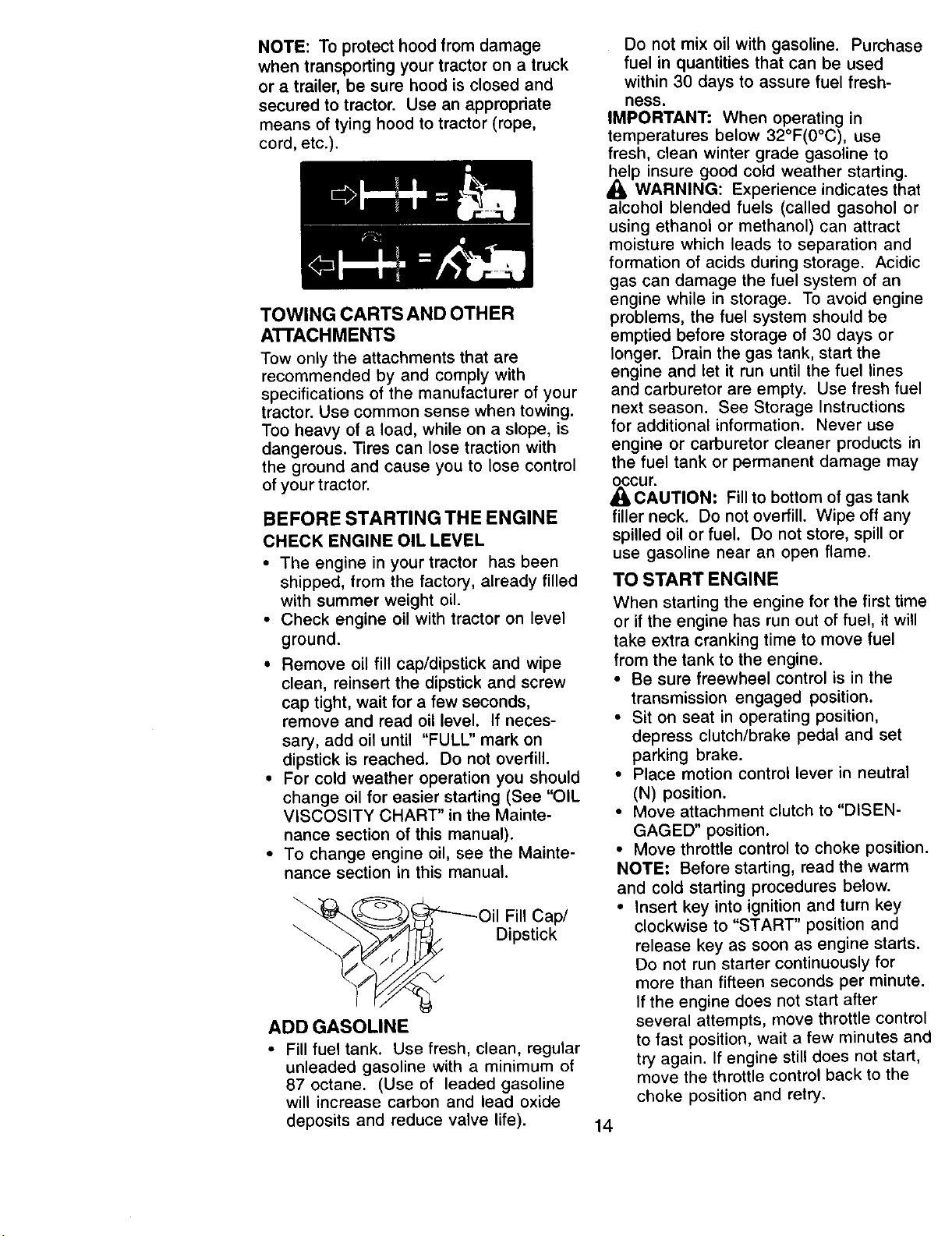
NOTE: To protect hood from damage
when transporting your tractor on a truck
or a trailer, be sure hood is closed and
secured to tractor. Use an appropriate
means of tying hood to tractor (rope,
cord, etc.).
TOWING CARTS AND OTHER
A'I-I'ACH MENTS
Tow only the attachments that are
recommended by and comply with
specifications of the manufacturer of your
tractor. Use common sense when towing.
Too heavy of a load, while on a slope, is
dangerous. Tires can lose traction with
the ground and cause you to lose control
of your tractor.
BEFORE STARTING THE ENGINE
CHECK ENGINE OIL LEVEL
• The engine in your tractor has been
shipped, from the factory, already filled
with summer weight oil.
• Check engine oil with tractor on level
ground.
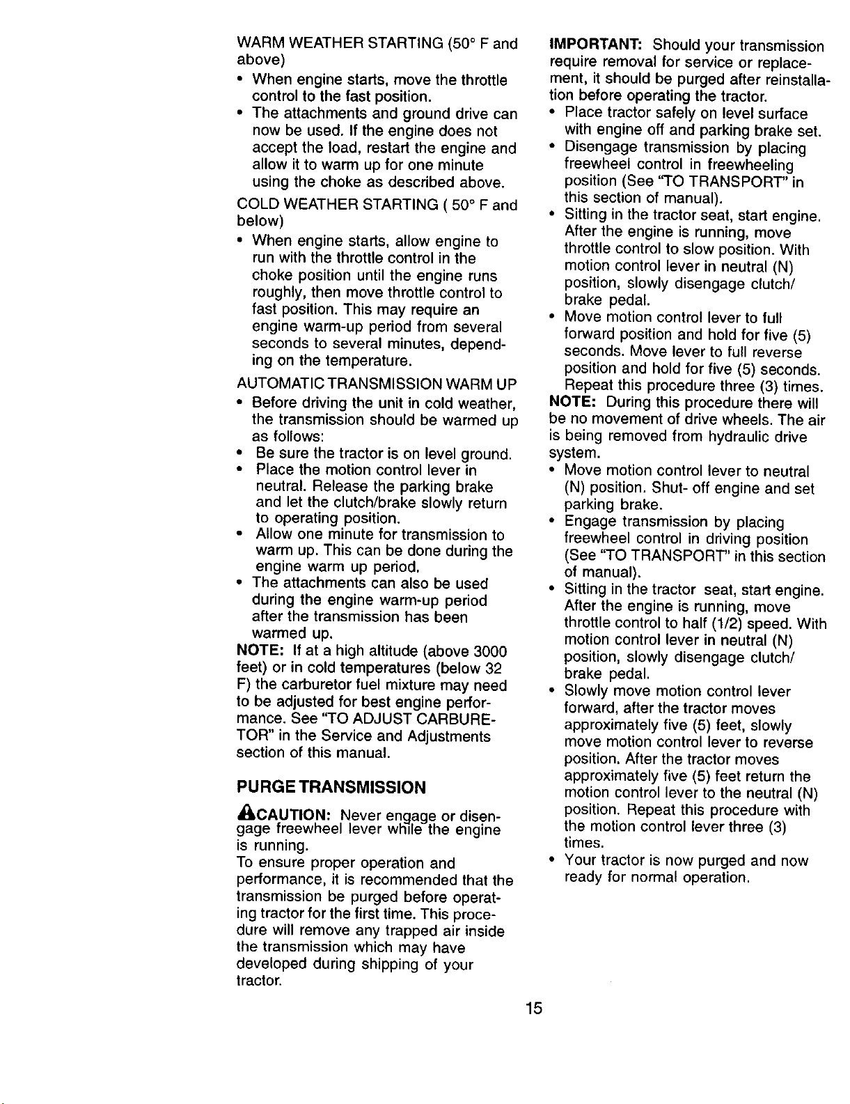
• Remove oil fill cap/dipstick and wipe
clean, reinsert the dipstick and screw
cap tight, wait for a few seconds,
remove and read oil level. If neces-
sary, add oil until "FULL" mark on
dipstick is reached. Do not overfill.
• For cold weather operation you should
change oil for easier starting (See "OIL
VISCOSITY CHART" in the Mainte-
nance section of this manual).
• To change engine oil, see the Mainte-
nance section in this manual.
Oil Fill Cap/
Dipstick
ADD GASOLINE
• Fill fuel tank. Use fresh, clean, regular
unleaded gasoline with a minimum of
87 octane. (Use of leaded gasoline
will increase carbon and lead oxide
deposits and reduce valve life).
Do not mix oil with gasoline. Purchase
fuel in quantities that can be used
within 30 days to assure fuel fresh-
ness.
IMPORTANT: When operating in
temperatures below 32°F(0°C), use
fresh, clean winter grade gasoline to
_lp insure good cold weather starting.
WARNING: Experience indicates that
alcohol blended fuels (called gasohol or
using ethanol or methanol) can attract
moisture which leads to separation and
formation of acids during storage. Acidic
gas can damage the fuel system of an
engine while in storage. To avoid engine
problems, the fuel system should be
emptied before storage of 30 days or
longer. Drain the gas tank, start the
engine and let it run until the fuel lines
and carburetor are empty. Use fresh fuel
next season. See Storage Instructions
for additional information. Never use
engine or carburetor cleaner products in
the fuel tank or permanent damage may
,_cur.
CAUTION: Fill to bottom of gas tank
filler neck. Do not overfill. Wipe off any
spilled oil or fuel. Do not store, spill or
use gasoline near an open flame.
TO START ENGINE
When starting the engine for the first time
or if the engine has run out of fuel, it will
take extra cranking time to move fuel
from the tank to the engine.
• Be sure freewheel control is in the
transmission engaged position.
• Sit on seat in operating position,
depress clutch/brake pedal and set
parking brake.
• Place motion control lever in neutral
(N) position.
• Move attachment clutch to "DISEN-
GAGED" position.
• Move throttle control to choke position.
NOTE: Before starting, read the warm
and cold starting procedures below.
• Insert key into ignition and turn key
clockwise to "START" position and
release key as soon as engine starts.
Do not run starter continuously for
more than fifteen seconds per minute.
If the engine does not start after
several attempts, move throttle control
to fast position, wait a few minutes and
try again. If engine still does not start,
move the throttle control back to the
choke position and retry.
14
Page 15
WARM WEATHER STARTING (50 ° F and
above)
• When engine starts, move the throttle
control to the fast position.
• The attachments and ground drive can
now be used. If the engine does not
accept the load, restart the engine and
allow it to warm up for one minute
using the choke as described above.
COLD WEATHER STARTING ( 50 ° F and
below)
• When engine starts, allow engine to
run with the throttle control in the
choke position until the engine runs
roughly, then move throttle control to
fast position. This may require an
engine warm-up period from several
seconds to several minutes, depend-
ing on the temperature.
AUTOMATIC TRANSMISSION WARM UP
• Before driving the unit in cold weather,
the transmission should be warmed up
as follows:
• Be sure the tractor is on level ground.
• Place the motion control lever in
neutral. Release the parking brake
and let the clutch/brake slowly return
to operating position.
• Allow one minute for transmission to
warm up. This can be done during the
engine warm up period.
• The attachments can also be used
during the engine warm-up period
after the transmission has been
warmed up.
NOTE: If at a high altitude (above 3000
feet) or in cold temperatures (below 32
F) the carburetor fuel mixture may need
to be adjusted for best engine perfor-
mance. See "TO ADJUST CARBURE-
TOR" in the Service and Adjustments
section of this manual.
PURGETRANSMISSION
_CAUTION: Never engage or disen-
gage freewneel lever wn e the engine
is running.
To ensure proper operation and
performance, it is recommended that the
transmission be purged before operat-
ing tractor for the first time. This proce-
dure will remove any trapped air inside
the transmission which may have
developed during shipping of your
tractor.
IMPORTANT: Should your transmissio
require removal for service or replace-
ment, it should be purged after reinstall
tion before operating the tractor.
• Place tractor safely on level surface
with engine off and parking brake sel
• Disengage transmission by placing
freewheel control in freewheeling
position (See "TO TRANSPORT" in
this section of manual).
• Sitting in the tractor seat, start engine
After the engine is running, move
throttle control to slow position. With
motion control lever in neutral (N)
position, slowly disengage clutch/
brake pedal.
• Move motion control lever to full
forward position and hold for five (5)
seconds. Move lever to full reverse
position and hold for five (5) seconds
Repeat this procedure three (3) time_
NOTE: During this procedure there will
be no movement of drive wheels. The a
is being removed from hydraulic drive
system.
• Move motion control lever to neutral
(N) position. Shut- off engine and set
parking brake.
• Engage transmission by placing
freewheel control in driving position
(See ''TO TRANSPORT" in this sectic
of manual).
• Sitting in the tractor seat, start engin_
After the engine is running, move
throttle control to half (1/2) speed. Wi
motion control lever in neutral (N)
position, slowly disengage clutch/
brake pedal.
• Slowly move motion control lever
forward, after the tractor moves
approximately five (5) feet, slowly
move motion control lever to reverse
position. After the tractor moves
approximately five (5) feet return the
motion control lever to the neutral (N)
position. Repeat this procedure with
the motion control lever three (3)
times.
• Your tractor is now purged and now
ready for normal operation.
15
Page 16
MOWING TIPS
• Mower should be properly leveled for
best mowing performance. See "TO
LEVEL MOWER HOUSING" in the
Service and Adjustments section of
this manual.
• The left hand side of mower should be
used for trimming.
• Drive so that clippings are discharged
onto the area that has been cut. Have
the cut area to the right of the tractor.
This will result in a more even distribu-
tion of clippings and more uniform
cutting.
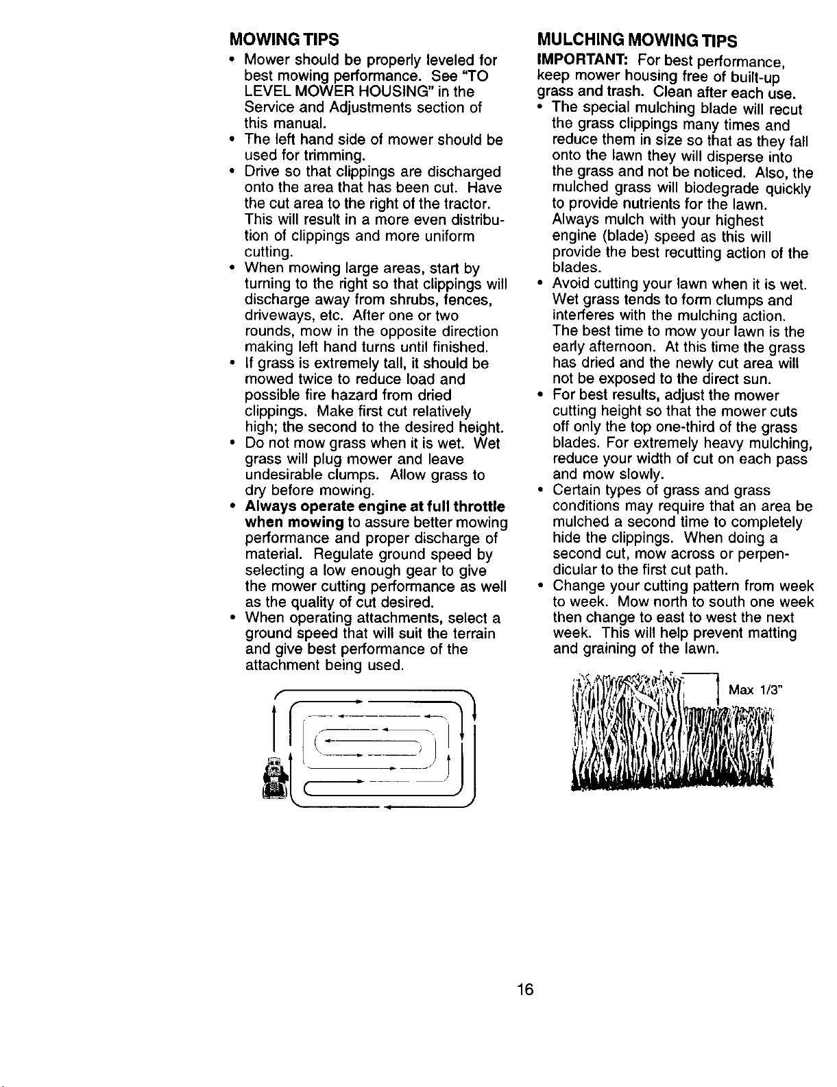
• When mowing large areas, start by
turning to the right so that clippings will
discharge away from shrubs, fences,
driveways, etc. After one or two
rounds, mow in the opposite direction
making left hand turns until finished.
• If grass is extremely tall, it should be
mowed twice to reduce load and
possible fire hazard from dried
clippings. Make first cut relatively
high; the second to the desired height.
• Do not mow grass when it is wet. Wet
grass will plug mower and leave
undesirable clumps. Allow grass to
dry before mowing.
• Always operate engine at full throttle
when mowing to assure better mowing
performance and proper discharge of
material. Regulate ground speed by
selecting a low enough gear to give
the mower cutting performance as well
as the quality of cut desired.
• When operating attachments, select a
ground speed that will suit the terrain
and give best performance of the
attachment being used.
f
MULCHING MOWING TIPS
IMPORTANT: For best performance,
keep mower housing free of built-up
grass and trash. Clean after each use.
• The special mulching blade will recut
the grass clippings many times and
reduce them in size so that as they fall
onto the lawn they will disperse into
the grass and not be noticed. Also, the
mulched grass will biodegrade quickly
to provide nutrients for the lawn.
Always mulch with your highest
engine (blade) speed as this will
provide the best recutting action of the
blades.
• Avoid cutting your lawn when it is wet.
Wet grass tends to form clumps and
interferes with the mulching action.
The best time to mow your lawn is the
early afternoon. At this time the grass
has dried and the newly cut area will
not be exposed to the direct sun.
• For best results, adjust the mower
cutting height so that the mower cuts
off only the top one-third of the grass
blades. For extremely heavy mulching,
reduce your width of cut on each pass
and mow slowly.
• Certain types of grass and grass
conditions may require that an area be
mulched a second time to completely
hide the clippings. When doing a
second cut, mow across or perpen-
dicular to the first cut path.
• Change your cutting pattern from week
to week. Mow north to south one week
then change to east to west the next
week. This will help prevent matting
and graining of the lawn.
Max 1/3"
16
Page 17
FILL IN DATES
AS¥OUOOMPLETE
Check Brake Operation
Check Tire Pressure _
Check Operator Presence and
T Interlc_kSystems Ik_
R Check for Loose Fasteners _ _7
T Lubrication Chart
0 Check Battery Level
Sharpen/Replace Mower Blades i4
R Clean Battery and Terminals
Check Transaxle Cooling i_ #
Adjust Blade Belt(s) Tension _s
Adjust Motion Drive Belt(s) Tension _s
Check Engine Oil Level _
Change Engine OIl _2,3
E Clean AIr Filter _:
a Clean Air Screen
Inspect Muffler/Spark Arrester V'
a Replace Oil Filter (If equipped) _ 2
E Clean Engine Cooling Fins V'2
Replace Spark Plug i_ v_
Replace Air Filter Paper Cartridge
Replace Fuel Filter V +
1 • Change more often when oper atir,_g ur,der a heavy load o¢ in high ambient lemperature$ 5 - II equipped wffh r_diust able system
2 • Se_ice more often when opera_ng _n dirty or dusly cond;_or ts 6. Not r_q_ired if eqtJipped with mlinter=ance.f tee battery
3 _ If oquipped with oil filter, change oil eve_/50 hours¸ 7 - Tighten front axle pivot bolt to 35 ff.-_s maximum¸
4 - Replace b_ade$ _qote Often when r_owittg it+ sindy soiJ Do not ove_ghten
GENERAL RECOMMENDATIONS
The warranty on this tractor does not
cover items that have been subjected to
operator abuse or negligence. To
receive full value from the warranty,
operator must maintain tractor as
instructed in this manual.
Some adjustments will need to be made
periodically to properly maintain your
tractor.
All adjustments in the Service and
Adjustments section of this manual
should be checked at least once each
season.
• Once a year you should replace the
spark plug, clean or replace air filter,
and check blades and belts for wear.
A new spark plug and clean air filter
assure proper air-fuel mixture and
help your engine run better and last
longer.
BEFORE EACH USE
• Check engine oil level.
• Check brake operation.
• Check tire pressure.
• Check operator presence and
interlock systems for proper operation.
• Check for loose fasteners.
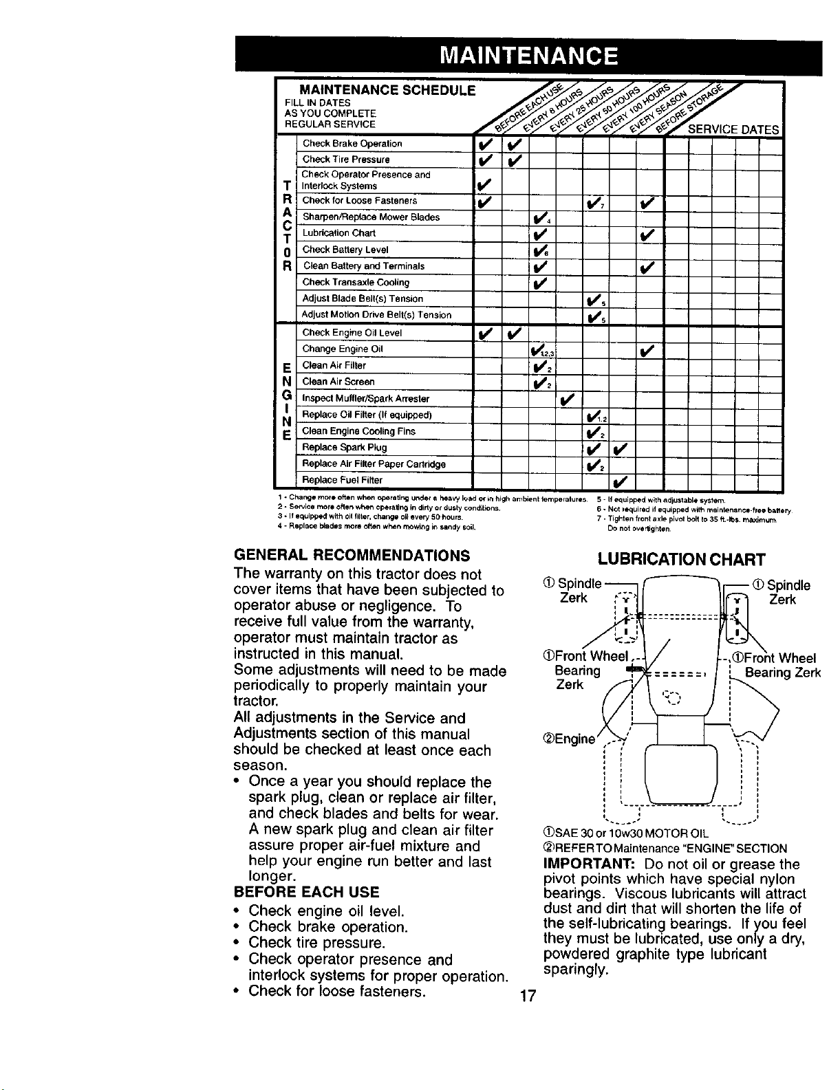
LUBRICATION CHART
Zerk Zerk
(_Front Wheel
Bearing
Zerk
I
_SAE 30 or10w30 MOTOR OIL
_REFER TO Maintenance "ENGINE" SECTION
IMPORTANT: Do not oil or grease the
pivot points which have special nylon
bearings• Viscous lubricants will attract
dust and dirt that will shorten the life of
the self-lubricating bearings. If 7ou feel
they must be lubricated, use omy a dry,
powdered graphite type lubricant
sparingly.
17
- _ Spindle
Bearing Zerk
Page 18
TRACTOR
Always observe safety rules when
performing any maintenance.
BRAKE OPERATION
If tractor requires more than six (6) feet
stopping distance at high speed in
highest gear, then brake must be
adjusted. (See "TO ADJUST BRAKE" in
the Service and Adjustments section of
this manual).
TIRES
• Maintain proper air pressure in all tires
(See "PRODUCT SPECIFICATIONS"
section of this manual).
• Keep tires free of gasoline, oil, or
insect control chemicals which can
harm rubber.
• Avoid stumps, stones, deep ruts, sharp
objects and other hazards that may
cause tire damage.
NOTE: To seal tire punctures and
prevent flat tires due to slow leaks, tire
sealant may be purchased from your
local parts dealer. Tire sealant also
prevents tire dry rot and corrosion.
OPERATOR PRESENCE SYSTEM
Be sure operator presence and interlock
systems are working properly. If your
tractor does not function as described,
repair the problem immediately.
• The engine should not start unless the
clutch/brake pedal is fully depressed
and attachement clutch control is in
the disengaged position.
• When the engine is running, any
attempt by the operator to leave the
seat without first setting the parking
brake should shut off the engine.
• When the engine is running and the
attachment clutch is engaged, any
attempt by the operator to leave the
seat should shut off the engine.
• The attachment clutch should never
operate unless the operator is in the
seat.
BLADE CARE
For best results mower blades must be
kept sharp. Replace bent or damaged
blades.
BLADE REMOVAL
• Raise mower to highest position to
allow access to blades.
• Remove hex bolt, lock washer and flat
washer securing blade.
• Install new or resharpened blade with
trailing edge up towards deck as
shown.
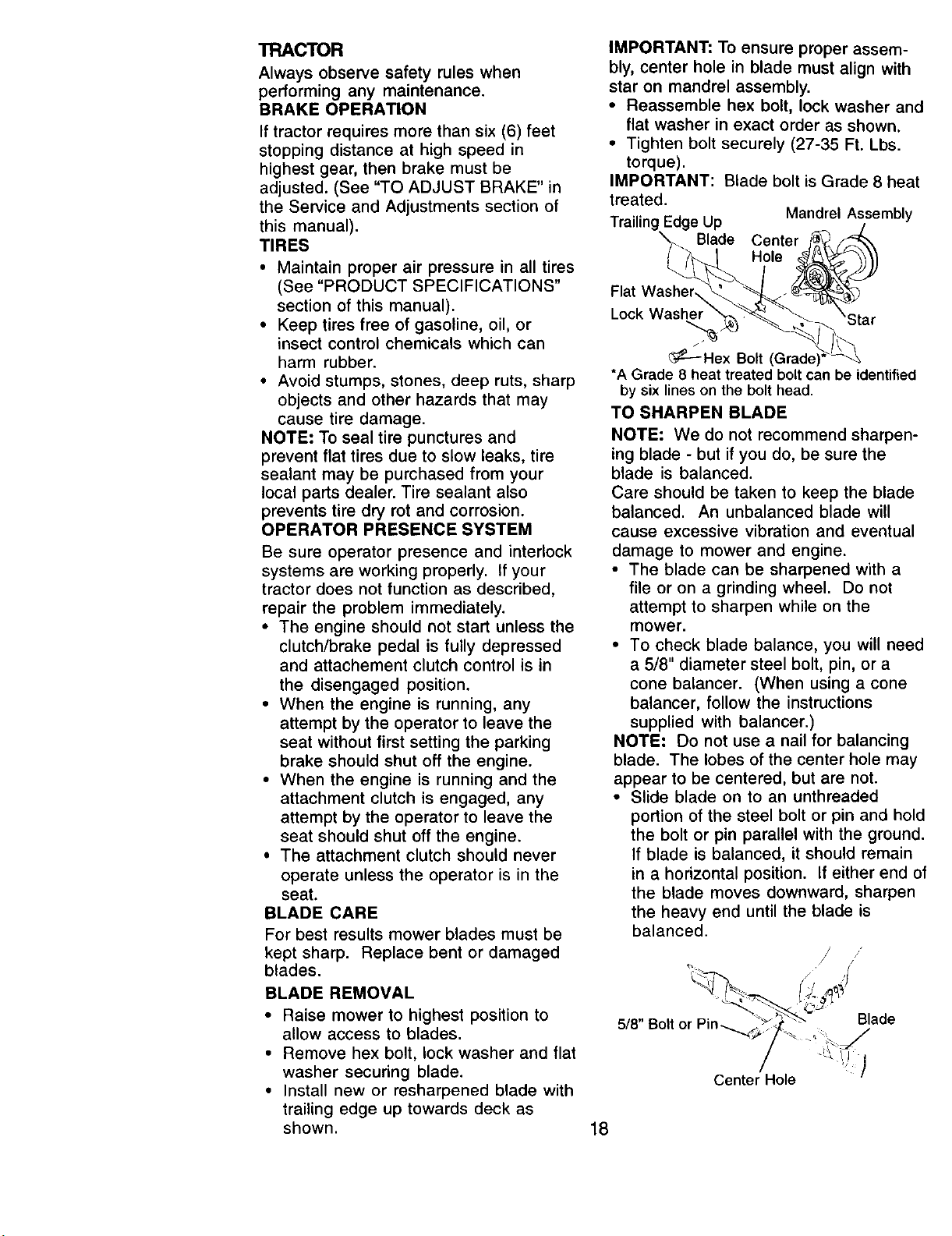
IMPORTANT: To ensure proper assem-
bly, center hole in blade must align with
star on mandrel assembly.
• Reassemble hex bolt, lock washer and
flat washer in exact order as shown.
• Tighten bolt securely (27-35 Ft. Lbs.
torque).
IMPORTANT: Blade bolt is Grade 8 heat
treated.
Trailing Edge Up
Blade Center
Flat Washer,
Lock Washer
_--Hex Bolt (Grade)
*A Grade 8 heat treated bolt can be identified
by six lines on the bolt head.
TO SHARPEN BLADE
NOTE: We do not recommend sharpen-
ing blade - but if you do, be sure the
blade is balanced.
Care should be taken to keep the blade
balanced. An unbalanced blade will
cause excessive vibration and eventual
damage to mower and engine.
• The blade can be sharpened with a
file or on a grinding wheel. Do not
attempt to sharpen while on the
mower.
• To check blade balance, you will need
a 5/8" diameter steel bolt, pin, or a
cone balancer. (When using a cone
balancer, follow the instructions
supplied with balancer.)
NOTE: Do not use a nail for balancing
blade. The lobes of the center hole may
appear to be centered, but are not.
• Slide blade on to an unthreaded
portion of the steel bolt or pin and hold
the bolt or pin parallel with the ground.
If blade is balanced, it should remain
in a horizontal position. If either end of
the blade moves downward, sharpen
the heavy end until the blade is
balanced.
5/8" Bolt or Pin_
Center Hole
Mandrel Assembly
Hole
Blade
18
Page 19

BA'n'ERY
Your tractor has a battery charging
system which is sufficient for normal use.
However, periodic charging of the battery
with an automotive charger will extend
its life.
• Keep battery and terminals clean.
• Keep battery bolts tight.
• Keep small vent holes open.
• Recharge at 6-10 amperes for 1 hour.
NOTE: The original equipment battery on
your tractor is maintenance free. Do not
attempt to open or remove caps or
covers. Adding or checking level of
electrolyte is not necessary.
TO CLEAN BATTERY AND TERMINALS
Corrosion and dirt on the battery and
terminals can cause the battery to "leak"
power.
• Open battery box door.
• Disconnect BLACK battery cable first
then RED battery cable and remove
battery from tractor.
• Rinse the battery with plain water and
dry.
• Clean terminals and battery cable
ends with wire brush until bright.
• Coat terminals with grease or petro-
leum jelly.
• Reinstall battery (See "REPLACING
BATTERY" in the SERVICE AND
ADJUSTMENTS section of this
manual).
V-BELTS
Check V-belts for deterioration and wear
after 100 hours of operation and replace
if necessary. The belts are not adjustable.
Replace belts if they begin to slip from
wear.
TRANSAXLE COOLING
The transmission fan and cooling fins
should be kept clean to assure proper
cooling.
Do not attempt to clean fan or transmis-
sion while engine is running or while the
transmission is hot. To prevent possible
damage to seals, do not use high
pressure water or steam to clean
transaxle.
• Inspect cooling fan to be sure fan
blades are intact and clean.
• Inspect cooling fins for dirt, grass
clippings and other materials. To
prevent damage to seals, do not use
compressed air or high pressure
sprayer to clean cooling fins.
TRANSAXLE PUMP FLUID
The transaxle was sealed at the factory
and fluid maintenance is not required for
the life of the transaxle. Should the
transaxle ever leak or require servicing,
contact your nearest authorized service
center/department.
ENGINE
LUBRICATION
Only use high quality detergent oil rated
with API service classification SF, SG or
SH. Select the oil's SAE viscosity grade
according to your expected operating
temperature.
NOTE: Although multi-viscosity oils
(5W30, 10W30 etc.) improve starting in
cold weather, these multi-viscosity oils
will result in increased oil consumption
when used above 32°E Check your
engine oil level more frequently to avoid
possible engine damage from running
low on oil.
Change the oil after every 25 hours of
operation or at least once a year if the
tractor is not used for 25 hours in one
year.
Check the crankcase oil level before
starting the engine and after each eight
(8) hours of operation. Tighten oil fill cap/
dipstick securely each time you check
the oi! level.
TO CHANGE ENGINE OIL
Determine temperature range expected
before oil change. All oil must meet API
service classification SF, SG or SH.
• Be sure tractor is on level surface.
• Oil will drain more freely when warm.
• Catch oil in a suitable container.
• Remove oil fill cap/dipstick. Be careful
not to allow dirt to enter the engine
when changing oil.
• Remove drain plug.
• After oil has drained completely,
replace oil drain plug and tighten
securely.
• Refill engine with oil through oil fill
dipstick tube. Pour slowly. Do not
overfill. For approximate capacity see
"PRODUCT SPECIFICATIONS"
section of this manual.
19
Page 20

• Use gauge on oil fill cap/dipstick for
checking level. Be sure dipstick cap is
tightened securely for accurate
reading. Keep oil at "FULL" line on
dipstick.
Oil Fill
Cap/Dipstick
OilDrain
CLEAN AIR SCREEN
Air screen must be kept free of dirt and
chaff to prevent engine damage from
overheating. Clean with a wire brush or
compressed air to remove dirt and
stubborn dried gum fibers.
ENGINE COOLING FINS
Remove any dust, dirt or oil from engine
cooling fins to prevent engine damage
from overheating.
• Remove screws from blower housing
and lift housing and dipstick tube
assembly off engine.
• Cover oil fill opening to prevent entry
of dirt.
• Use compressed air or stiff bristle
brush to thoroughly clean engine
cooling fins.
• To reassemble, reverse above
procedure.
Screws Screws
Dipstick Tube
Assembly
Engine
Cooling
Fins
AIR FILTER
Your engine will not run properly using a
dirty air filter. Clean the foam pre-cleaner
after every 25 hours of operation or
every season. Service paper cartridge
every 100 hours of operation or every
season, whichever occurs first.
Service air cleaner more often under
dusty conditions.
• Remove knob(s) and cover.
TO SERVICE PRE-CLEANER
• Slide foam pre-cleaner off cartridge.
• Wash it in liquid detergent and water.
• Squeeze it dry in a clean cloth.
• Saturate it in engine oil. Wrap it in
clean, absorbent cloth and squeeze to
remove excess oil.
Blower Housing
• If very dirty or damaged, replace pre-
cleaner.
• Reinstall pre-cleaner over cartridge.
• Reinstall cover and secure with
knob(s).
TO SERVICE CARTRIDGE
• Remove cartridge nut.
• Carefully remove cartridge to prevent
debris from entering carburetor. Clean
base carefully to prevent debris from
entering carburetor.
• Clean cartridge by tapping gently on
flat surface. If very dirty or damaged,
replace cartridge.
• Reinstall cartridge, nut, precleaner,
cover and secure with knob(s).
IMPORTANT: Petroleum solvents, such
as kerosene, are not to be used to clean
the cartridge. They may cause deteriora-
tion of the cartridge. Do not oil cartridge.
Do not use pressurized air to clean or dry
cartridge. _ Cover
-i_ i Knob
Cover _._;'_ Cartridge
_ Nut
_;_ Paper
Foam Pre- ...i--_ ._ Cartridge
Cleaner
_li;_../Base
MUFFLER
Inspect and replace corroded muffler
and spark arrester (if equipped) as it
could create a fire hazard and/or
damage.
SPARKPLUGS
Replace spark plugs at the beginning of
each mowing season or after every 100
hours of operation, whichever occurs
first. Spark plug type and gap setting are
shown in "PRODUCT SPECIFICATIONS"
section of this manual.
IN-LINE FUEL FILTER
The fuel filter should be replaced once
each season. If fuel filter becomes
clogged, obstructing fuel flow to carbure-
tor, replacement is required.
• With engine cool, remove filter and
plug fuel line sections.
• Place new fuel filter in position in fuel
line with arrow pointing towards
carburetor.
• Be sure there are no fuel line leaks
and clamps are properly positioned.
• Immediately wipe up any spilled
gasoline.
20
Page 21

free of all gasoline, oil, etc.
• Protect painted surfaces with automo
tive type wax.
We do not recommend using a garden
hose to clean your tractor unless the
CLEANING
• Clean engine, battery, seat, finish, etc.
of all foreign matter.
• Keep finished surfaces and wheels
CAUTION: Before performing any service or adjustments:
Depress clutch/brake pedal fully and set parking brake.
• Place motion control lever in neutral (N) position.
• Place attachment clutch in "DISENGAGED" position.
Turn ignition key "OFF" and remove key.
Make sure the blades and all moving parts have completely stopped.
• Disconnect spark plug wire from spark plug and place wire where it cannot come
in contact with plug.Tractor
electrical system, muffler, air filter and
carburetor are covered to keep water OL
Water in engine can result in a short-
ened engine life.
TRACTOR
TO REMOVE MOWER
Mower will be easier to remove from the
right side of tractor.
• Place attachment clutch in "DISEN-
GAGED" position.
• Move attachment lift lever forward to
lower mower to its lowest position.
• Roll belt off engine puUey.
• Remove small retainer spring, and lift
clutch spring off pulley bolt.
• Remove large retainer spring, slide
collar off and push housing guide out
of bracket.
• Disconnect anti-swaybar from chassis
bracket by removing retainer spring.
• Disconnect suspension arms from rear
deck brackets by removing retainer
springs.
• Disconnect front links from deck by
removing retainer springs.
Small Retainer Spring
Clutch
• Raise lift lever to raise suspension
arms. Slide mower out from under
tractor.
IMPORTANT: If an attachment other tha
the mower deck is to be mounted on th_
tractor, remove the front links and hook
the clutch spring onto square hole in
frame.
TO INSTALL MOWER
• Raise attachment lift lever to its
highest position.
• Slide mower under tractor with
discharge guard to right side of tracto
• Lower lift lever to its lowest position.
• Install mower in reverse order of
removal instructions.
Retainer
Anti-Sway
Housing Guide Br_
Large Retainer Spring
Link
_prirtgs
(Both Sides)
21
Page 22

TO LEVEL MOWER HOUSING
Adjust the mower while tractor is parked
on level ground or driveway• Make sure
• , _l D
t=res areproperly inflated (See PRO -
UCT SPECIFICATIONS" section of this
manual). If tires are over or
underinflated, you will not properly
adjust your mower.
SIDE-TO-SIDE ADJUSTMENT
• Raise mower to its highest position.
• At the midpoint of both sides of mower,
measure height from bottom edge of
mower to ground. Distance "A" on
both sides of mower should be the
same or within 1/4" of each other.
• If adjustment is necessary, make
adjustment on one side of mower only.
• To raise one side of mower, tighten lift
link adjustment nut on that side.
• To lower one side of mower, loosen lift
link adjustment nut on that side.
NOTE: Each full turn of adjustment nut
witl change mower height about 1/8".
• Recheck measurements after adjust-
ing.
Bottom edge of Bottom edge of
mower to mower to
ground _ ground
Before making any necessary adjust-
ments, check that both front links are
equal in length. Both links should be
approximately 10-3/8".
If links are not equal in length, adjust
one link to same length as other link.
To lower front of mower loosen nut "E'
on both front links an equal number o
turns.
When distance "D" is 1/8" to 1/2" Iowe
at front than rear, tighten nuts "F"
against trunnion on both front links.
To raise front of mower, loosen nut "F
from trunnion on both front links.
Tighten nut "E" on both front links an
equal number of turns.
When distance "D" is 1/8" to 1/2" Iow_
at front than rear, tighten nut "F"
against trunnion on both front links.
Recheck side-to-side adjustment.
oo\_ , oo/ /. Mandrel
Both Front Links Should be Equal in Lengtt_
A_-\- '_JGmund Line_- JT A
©
, Suspension Arm
Lift Link
Adjustment Nut
FRONT-TO-BACK ADJUSTMENT
IMPORTANT: Deck must be level side-to
side. If the following front-to-back
adjustment is necessary, be sure to
adjust both front links equally so mower
will stay level side-to-side.
To obtain the best cutting results, the
mower housing should be adjusted so
that the |font is approximately 1/8" to 1/2"
lower than the rear when the mower is in
its highest position.
Check adjustment on right side of tractor.
Measure distance "D" directly in front
and behind the mandrel at bottom edge
of mower housing as shown.
Nut
TrL
Front Links
22
Page 23

TO REPLACE MOWER BLADE
DRIVE BELT
The mower blade drive belt may be
replaced without tools. Park the tractor
on level surface. Engage parking brake.
BELT REMOVAL-
• Remove mower from tractor (See 'q-O
REMOVE MOWER" in this section of
this manual).
• Work belt off both mandrel pulleys and
idler pulleys.
• Pull belt away from mower.
BELT INSTALLATION -
• Install new belt in reverse order of
removal.
• Make sure belt is in all pulley grooves
and inside all belt guides.
• Install mower in reverse order of
removal instructions.
Mandrel
Pulley j j
TO ADJUST BRAKE
Your tractor is equipped with an adjust-
able brake system which is mounted on
the side of the transaxte.
If tractor requires more than six (6) feet
stopping distance at high speed in
highest gear, then brake must be
adjusted.
• Depress clutch/brake pedal and
engage parking brake.
• Measure distance between brake
operating arm and nut "A" on brake
rod.
• If distance is other than 1-9/16", loosen
jam nut and turn nut "A" until distance
becomes 1-9/16". Retighten jam nut
against nut "A".
• Road test tractor for proper stopping
distance as stated above. Readjust if
necessary. If stopping distance is still
greater than six (6) feet in highest
gear, further maintenance is neces-
sary. Contact your nearest authorized
service center/department.
With Parking Brake "Engaged"
Nut "A"
Jam Nut
\
Arm
_ _J
Do Not touch this nut. If further brake
adjustment is necessary contact your
nearest authorized service center/
department
TO REPLACE MOTION DRIVE BEL
Park the tractor on level surface. En-
gage parking brake. For assistance,
there is a belt installation guide decal (
bottom side of left footrest.
• Remove mower (See "TO REMOVE
MOWER" in this section of this
manual.)
• Remove belt from stationary idler ant
clutching idler.
• Pul! belt slack toward rear of tractor.
Carefully remove belt upwards from
transmission input pulley and over
cooling fan blades.
• Pull belt toward front of tractor and
remove downward from around
engine pulley.
• Install new belt by reversing above
procedure.
Engine____._._____
Pulley
Clutching Idler--
Stationary Idler----.
Transmission
Input Pulley\
23
Page 24

TRANSAXLE MOTION CONTROL
LEVER NEUTRAL ADJUSTMENT
The motion control lever has been preset
at the factory and adjustment should not
be necessary.
• Loosen adjustment bolt in front of the
right rear wheel, and lightly tighten.
• Start engine and move motion control
lever until tractor does not move
forward or backward.
• Hold motion control lever in that
position and turn engine off.
• While holding motion control lever in
place, loosen the adjustment bolt.
• Move motion control lever to the
neutral (N) (lock gate) position.
• Tighten adjustment bolt securely.
NOTE: If additional clearance is needed
to get to adjustment bolt, move mower
deck height to the lowest position.
After above adjustment is made, if the
tractor still creeps forward or backward
while motion control lever is in neutral
position, follow these steps:
• Loosen the adjustment bolt.
• Move the motion control lever 1/4 to
1/2 inch in the direction it is trying to
creep.
• Tighten adjustment bolt securely.
• Start engine and test.
• If tractor still creeps, repeat above
steps until satisfied.
Motion Control Lever Lock Gate
Neutral
FRONT WHEEL TOE-IN/CAMBER
The front wheel toe-in and camber are
not adjustable on your tractor. If damage
has occurred to affect the front wheel
toe-in or camber, contact your nearest
authorized service center/department.
TO REMOVE WHEEL FOR REPAIRS
• Block up axle securely.
• Remove axle cover, retaining ring and
washers to allow wheel removal (rear
wheel contains a square key - Do not
lose).
• Repair tire and reassemble.
• On rear wheels only: align grooves in
rear wheel hub and axle. Insert
square key.
• Replace washers and snap retaining
ring securely in axle groove.
• Replace axle cover.
NOTE; To seal tire punctures and
prevent flat tires due to slow leaks, tire
sealant may be purchased from your
local parts dealer. Tire sealant also
prevents tire dry rot and corrosion.
Washers
Retaining
Axle
Cover
"o
i
Square Key.....-.-_
(Rear Wheel Only)
Adjustment Bolt
TRANSMISSION REMOVAL/
REPLACEMENT
Should your transmission require
removal for service or replacement, it
should be purged after reinstallation and
before operating the tractor. See
"PURGE TRANSMISSION" in the
Operation section of this manual.
TO ADJUST STEERING WHEEL
ALIGNMENT
If steering wheel crossbars are not
horizontal (left to right) when wheels are
positioned straight forward, remove
steering wheel and reassemble per
instructions in the Assembly section of
this manual.
TO START ENGINE WITH A WEAK
BAI-FERY
ACAUTION: Lead-acid batteries
generate explosive gases. Keep sparks,
flame and smoking materials away from
batteries. Always wear eye protection
when around batteries.
If your battery is too weak to start the
engine, it should be recharged. (See
"BATTERY" in the MAINTENANCE
section of this manual).
If "jumper cables" are used for emer-
gency starting, follow this procedure:
IMPORTANT: Your tractor is equipped
with a 12 volt negative grounded system.
The other vehicle must also be a 12 volt
negative grounded system. Do not use
your tractor battery to start other vehicles.
24
Page 25

TO ATTACH JUMPER CABLES -
• Connect each end of the RED cable to
the POSITIVE (+) terminal of each
battery, taking care not to short against
chassis.
• Connect one end of the BLACK cable
to the NEGATWE (-) terminal of fully
charged battery.
• Connect the other end of the BLACK
cable to good CHASSIS GROUND,
away from fuel tank and battery.
TO REMOVE CABLES, REVERSE
ORDER -
• BLACK cable first from chassis and
then from the fully charged battery.
• RED cable last from both batteries.
Positive Terminal Negative Terminal
Battery
Positive Terminal
REPLACING BATTERY
_, CAUTION: Do not short battery
terminals by allowing a wrench or any
other object to contact both terminals at
the same time. Before connecting battery,
remove metal bracelets, wristwatch
bands,rings,etc.
Positive terminal must be connected first
to prevent sparking from accidental
grounding.
• Lift seat pan to raised position and
open battery box door.
• Disconnect BLACK battery cable first
then RED battery cable and carefully
remove battery from tractor.
• Install new battery with terminals in
same position as old battery.
• First connect RED battery cable to
positive (+) terminal with hex bolt and
nut as shown. Tighten securely.
• Connect BLACK grounding cable to
negative (-) terminal with remaining
hex bolt and nut. Tighten securely.
• Close battery box door.
Negative Terminal
Battery
Box
Keps-_
Positive (Red) Cable Negative' (Black)
Cable
TO REPLACE HEADLIGHT BULB
• Raise hood.
• Pull bulb holder out of the hole in the
backside of the grill.
• Replace bulb in holder and push bull
holder securely back into the hole in
the backside of the grill.
• Close hood.
INTERLOCKS AND RELAYS
Loose or damaged wiring may cause
your tractor to run poorly, stop running,
prevent it from starting.
• Check wiring. Sea electrical wiring
diagram in the Repair Parts section.
TO REPLACE FUSE
Replace with 15 amp automotive-type
plug-in fuse. The fuse holder is located
behind the dash.
TO REMOVE HOOD AND GRILL
ASSEMBLY
• Raise hood.
• Unsnap headlight wire connector.
• Stand in front of tractor. Grasp hood
sides, tilt toward engine and lift off of
tractor.
• To replace, reverse above procedure
/
Hood
Headlight Wire
Connector
25
Page 26

ENGINE
Maintenance, repair, or replacement of
the emission control devices and
systems, which are being done at the
customers expense, may be performed
by any non-road engine repair establish-
ment or individual. Warranty repairs must
be performed by an authorized engine
manufacturer's service outlet.
TO ADJUST THROTTLE CONTROL
CABLE
The throttle control has been preset at
the factory and adjustment should not be
necessary. Check adjustment as
described below before loosening cable.
If adjustment is necessary, proceed as
follows:
• With engine not running, move throttle
control lever from slow to choke
position. Slowly move lever from
choke to fast position.
• Check that holes "A" in governor
control lever and hole in governor
plate line-up, if holes "A" are not
aligned, loosen clamp screw and
move throttle cable until holes are
aligned. Tighten clamp screw se-
curely.
TO ADJUST CARBURETOR
NOTE: The carburetor on this engine is
low emission. It is equipped with an idle
fuel adjusting needle with a limiter cap,
which allows some adjustment within
the limits allowed by the cap, Do not
attempt to remove the limiter cap. The
limiter cap cannot be removed without
breaking the adjusting needle.
The carburetor has been preset at the
factory and adjustment should not be
necessary. However, minor adjustment
may be required to compensate for
differences in fuel, temperature, altitude
or load. If the carburetor does need
adjustment, proceed as follows:
In general, turning idle mixture valve in
(clockwise) decreases the supply of fuel
to the engine giving a leaner fuel/air
mixture. Turning the idle mixture valve
out (counterclockwise) increases the
supply of fuel to the engine giving a
richer fuel/air mixture.
IMPORTANT: Damage to the needle
valve and the seatin carburetor may
result if screw is turned in too tight.
Governor
Control Lever
Holes "A" Clamp Screw Cable
Governor
Plate
26
Page 27

PRELIMINARY SETTING -
• Air cleaner assembly must be as-
sembled to the carburetor when
making carburetor adjustments.
• Be sure the throttle control cable is
adjusted properly (see above).
FINAL SETTING -
• Start engine and allow to warm for five
minutes. Make final adjustments with
engine running and shift/motion control
lever in neutral (N) position.
• Move throttle control lever to slow
position. With finger, rotate and hold
throttle lever against idle speed screw.
Turn idle speed screw to attain 1750
RPM.
• While still holding throttle lever against
idle speed screw, turn idle mixture
valve full travel clockwise then counter-
clockwise until engine runs rough.
Turn valve to a point midway between
those two positions. Release throttle
lever.
ACCELERATION TEST -
• Move throttle control lever from slow to
fast position. If engine hesitates or
dies, turn idle mixture valve out
(counterclockwise) 1/8 turn. Repeat
test and continue to adjust, if neces-
sary, until engine accelerates smoothly.
High speed stop is factory adjusted. Do
not adjust - damage may result.
IMPORTANT: Never tamper with the
engine governor, which is factory set for
proper engine speed. Overspeeding the
engine above the factory high speed
setting can be dangerous. If you think the
engine-governed high speed needs
adjusting, contact your nearest autho-
rized service center/department, which
has proper equipment and experience to
make any necessary adjustments.
Idle Speed
Screw
Idle Mixture Valve _
with Limiter
27
Page 28

Immediately prepare your tractor for
storage at the end of the season or if the
tractor will not be used for 30 days or
more.
CAUTION: Never store the tractor
with gasoline in the tank inside a
building where fumes may reach an
open flame or spark. Allow the engine to
cool before storing in any enclosure.
TRACTOR
Remove mower from tractor for winter
storage. When mower is to be stored for
a period of time, clean it thoroughly,
remove all dirt, grease, leaves, etc. Store
in a clean, dry area.
• Clean entire tractor (See "CLEANING"
in the Maintenance section of this
manual).
• Inspect and replace belts, if necessary
(See belt replacement instructions in
the Service and Adjustments section of
this manual).
• Lubricate as shown in the Mainte-
nance section of this manual.
• Be sure that all nuts, bolts and screws
are securely fastened. Inspect moving
parts for damage, breakage and wear.
Replace if necessary.
• Touch up all rusted or chipped paint
surfaces; sand lightly before painting.
BATrERY
• Fully charge the battery for storage.
• After a period of time in storage,
battery may require recharging.
• To help prevent corrosion and power
leakage during long periods of
storage, battery cables should be
disconnected and battery cleaned
thoroughly (see "TO CLEAN BATTERY
AND TERMINALS" in the Maintenance
section of this manual).
• After cleaning, leave cables discon-
nected and place cables where they
cannot come in contact with battery
terminals.
• If battery is removed from tractor for
storage, do not store battery directly on
concrete or damp surfaces.
ENGINE
FUEL SYSTEM
IMPORTANT: It is important to prevent
_uUmdeposits from forming in essential
el system parts such as carburetor, fuel
filter, fuel hose, or tank during storage.
Also, experience indicates that alcohol
blended fuels 9called gasohol or using
ethanol or methanol) can attract moisture
which leads to separation and formation
of acids during storage. Acidic gas can
damage the fuel system of an engine
while in storage.
• Drain the fuel tank.
• Start the engine and let it run until the
fuel lines and carburetor are empty.
• Never use engine or carburetor
cleaner products in the fuel tank or
permanent damage may occur.
• Use fresh fuel next season.
NOTE" Fue! stabilizer is an acceptable
alternative in minimizing the formation of
fuel gum deposits during storage. Add
stabilizer to gasoline in fuel tank or
storage container. Always follow the mix
ratio found on stabilizer container. Run
engine at least 10 minutes after adding
stabilizer to allow the stabilizer to reach
the carburetor. Do not drain the gas tank
and carburetor if using fuel stabilizer.
ENGINEOIL
Drain oil (with engine warm) and replace
with clean engine oil. (See "ENGINE" in
the Maintenance section of this manual).
CYLINDER(S)
• Remove spark plug(s).
• Pour one ounce of oil through spark
plug hole(s) into cylinder(s).
• Turn ignition key to "START" position
for a few seconds to distribute oil.
• Replace with new spark plug(s).
OTHER
• Do not store gasoline from one season
to another.
• Replace your gasoline can if your can
starts to rust. Rust and/or dirt in your
gasoline will cause problems.
• If possible, store your tractor indoors
and cover it to give protection from
dust and dirt.
• Cover your tractor with a suitable
protective cover that does not retain
moisture. Do not use plastic. Plastic
cannot breathe which allows conden-
sation to form and wil! cause your
tractor to rust.
IMPORTANT: Never cover tractor while
engine and exhaust areas are still
warm.
28
Page 29

TROUBLESHOOTINGCHART
i PROBLEM
iWill not start
Hard to start
CAUSE
• Out of fuel.
• Engine not "CHOKED"
properly.
• Engine flooded.
• Bad spark plug.
• Dirty air filter.
• Dirty fuel filter.
• Water in fuel.
• Loose or damaged wiring.
• Carburetor out of adjustment
Service Adjustments
• Engine valves out of
adjustment.
• Dirty air filter.
• Bad spark plug.
• Weak or dead battery.
• Dirty fuel filter.
• Stale or dirty fuel.
• Loose or damaged wiring. •
• Carburetor out of adjustment •
Engine valves out of
adjustment.
CORRECTION
• Fill fuel tank.
• See "TO START ENGINE"
in Operation section.
• Wait several minutes before
attempting to start.
• Replace spark plug.
• Clean/replace air filter.
• Replace fuel filter.
• Drain fuel tank and carbure
tor, refill tank with fresh
gasoline and replace fuel
filter.
• Check all wiring.
• See ''To Adjust Carburetor" in
section.
• Contact an authorized
service center/department.
• Clean/replace air filter.
• Replace spark plug.
• Recharge or replace battery.
• Replace fuel filter.
• Drain fuel tank and refill with
fresh gasoline.
Check all wiring.
See "To Adjust Carburetor" in
Service Adjustments
section.
• Contact an authorized service
center/department.
Enginewill not
turn over
Engine clicks but
will not start
• Clutch/brake pedal not
depressed
• Attachment clutch is
engaged.
• Weak or dead battery.
• Blown fuse.
• Corroded battery terminals.
• Loose or damaged wiring.
• Faulty ignition switch.
• Faulty solenoid or starter.
Faulty operator presence
switch(es).
• Weak or dead battery.
• Corroded battery terminals.
• Loose or damaged wiring.
• Faulty solenoid or starter.
Depress clutch/brake pedal.
Disengage attachment clutch.
• Recharge or replace battery.
• Replace fuse.
• Clean battery terminals.
• Check all wiring.
• Check/replace ignition switch.
• Check/replace solenoid or
starter.
• Contact an authorized service
center/department.
• Recharge or replace battery.
• Clean battery terminals.
• Check all wiring.
• Check/replace solenoid or
starter.
29
Page 30

TROUBLESHOOTING CHART
PROBLEM
CAUSE
CORRECTION
Loss of power
Cutting too much grass/too
fast.
Throttle in "CHOKE"
position.
Build-up of grass, leaves •
and trash under mower.
Dirty air filter. •
Low oil level/dirty oil. •
Faulty spark plug. •
• Dirty fuel filter.
• Stale or dirty fuel.
• Water in fuel.
• Spark plug wire loose.
Dirty engine air screen/fins. •
Dirty/clogged muffler. •
Loose or damaged wiring. •
Carburetor out of •
adjustment.
Engine valves out of •
adjustment.
• Set in "Higher Cut" position/
reduce speed.
• Adjust throttle control.
Clean underside of mower
housing.
Clean/replace air filter.
Check oil level/change oil.
Clean and regap or change
spark plug.
Replace fuel filter.
Drain fuel tank and refill with
fresh gasoline.
Drain fuel tank and carbure-
tor, refill tank with fresh
gasoline and replace fuel
filter.
Connect and tighten spark
plug wire.
Clean engine air screen/
fins.
Clean/replace muffler.
Check all wiring.
See "To Adjust Carburetor"
in Service Adjustments
section.
Contact an authorized
service center/department.
Excessive •
vibration
Enginecontinues •
to run when
operator leaves
seat with
attachment
clutch engaged
Poor cut- uneven •
Worn, bent or loose blade. •
Bent blade mandrel. •
Loose/damaged part(s). •
Faulty operator-safety •
presence control system.
Worn, bent or loose blade. •
Mower deck not level. •
Buildup of grass, leaves, •
and trash under mower.
Bent blade mandrel. •
Clogged mower deck vent •
from build-up of grass,
leaves, and trash around
mandrels.
Replace blade.
Tighten blade bolt.
Replace blade mandrel.
Tighten loose part(s).
Replace damaged parts.
Check wiring, switches and
connections. If not corrected
contact an authorized
service center/department.
Replace blade. Tighten
blade bolt.
Level mower deck.
Clean underside of mower
housing.
Replace blade mandrel.
Clean around mandrels to
open vent holes.
3O
Page 31

TROUBLESHOOTING CHART
=ROBLEM CAUSE
_owerbladeswill
not rotate
• Obstruction in clutch
mechanism.
• Worn/damaged mower
drive belt.
• Frozen idler pulley.
• Frozen blade mandrel.
CORRECTION
• Remove obstruction.
• Replace mower drive belt.
• Replace idler pulley.
• Replace blade mandrel.
Poor grass
discharge
Headlight(s) not •
working •
(if so equipped) •
• Engine speed too slow.
• Travel speed too fast.
• Wet grass.
Mower deck not level.
Low/uneven tire air pressure.
Worn, bent or loose blade.
Buildup of grass, leaves and
trash under mower.
Mower drive belt worn.
Blades improperly installed.
Improper blades used.
Clogged mower deck vent
holes from buildup of
grass, leaves, and trash
around mandrels.
Switch is "OFF".
Bulb(s) burned out.
Faulty light switch.
Loose or damaged wiring.
Blown fuse.
• Place throttle control in
"FAST" position.
• Shift to slower speed.
• Allow grass to dry before
mowing.
• Level mower deck.
• Check tires for proper air
pressure.
• Replace/sharpen blade.
Tighten blade bolt.
• Clean underside of mower
housing.
• Replace mower drive belt.
• Reinstall blades sharp eric
down.
• Replace with blades listed
this manual.
• Clean around mandrels to
open vent holes.
• Turn switch "ON".
• Replace bulb(s).
• Check/replace light switch.
• Check wiring and connec
tions.
• Replace fuse.
Battery will not •
charge •
Loss of drive •
Engine "backfires" •
when turning
engine
"OFF"
Bad battery cell(s).
Poor cable connections.
Faulty regulator
(if so equipped).
Faulty alternator.
Freewheel control in
"disengaged" position.
Motion drive belt worn,
damaged, or broken.
Air trapped in transmission
during shipment or
servicing.
Engine throttle control not
set at "SLOW"
position for 30 seconds
stopping engine.
31
• Replace battery.
• Check/clean all connection
• Replace regulator.
Replace alternator.
• Place freewheel control in
"engaged" position.
• Replace motion drive belt.
Purge transmission.
Move throttle control to
"SLOW" position and allow
to idle for 30 seconds befor
stopping engine.
Page 32

NOTES
32
Page 33

SCHEMATIC
TRACTOR- - MODEL NUMBER 917.270680
RED
BATrERY
AMMETER FUSE
RE O
w.,_ '© ' ,O--:-----
Je M_
_)G At( (PEDAL UP)
IGNITION
SWITCH
/7
/
__ (2 PLUGSON
C_UT-ChI_BR-AKE
(OPTIONAL) _ SPARK
', FUEL; UNIT
BLUE II LINE : TWIN CYL,ENGINES)
i I
L I _lL . _ _'_________ '.........
FUELSHUT*OFF SOLENOID RED I I
(IFSO EQUIPPED) r LJGF_TINGSYSTEMOUTPUTDIODE I
BLACK
BLACK
ORANGE
i I
*_ _ BLACK •
RED
SOLENO,D
[_!! I STARTER
........ (NOT OCCUPIED)
W_TE I I /_/ ....... i
I 61_c K I BlOC K
ATT'MENTCLUTCH .....
CLUT H OFF GROUNDING
A
BLACK IGNITION _ GAP _----
(_ PLUG
CHARGING SYSTEM OUTPUT 21_ VOLTS AC MIN a 3_30 RpM
3 AMe DC O 36_ RPM {CHARGING SYSTEM DISCONNECTED
5AMP AC @ _ RPM_TPUT_I C)_ODE I_A_!1
SEAT SWITCH
IGNITION SWITCH
POSIllON CIRCUIT =MAKE"
OFF M+G+A1 NONE
RUN/LIGHT B+A1 A2+L
RUN B+A1 NONE
START B+S+A1 NONE
NOTE
YOUR TRACTOR IS
EQUIPPED WITH A SPECIAL
ALTERNATOR SYSTEM.
THE LIGHTS ARE NOT
CONNECTED TO THE
BATTERY, BUT HAVE THEIR
OWN ELECTRICAL SOURCE,
BROWN
HEADLIGHTS
BECAUSE OF THIS, THE
BRIGHTNESS OF THE LIGHTS
WILL CHANGE WITH ENGINE
SPEED. AT IDLE THE LIGHTS
WILL DIM. AS THE ENGINE IS
SPEEDED UP, THE LIGHTS
WILL BECOME THEIR BRIGHTEST.
NON-REMOVABLE
CONNECTIONS
REMOVABLE
CONNECTIONS
WIRING INSULATED CLIPS
NOTE: IF WIRING INSULATED CLIPS WERE REMOVED FOR
SERVICING OF UNIT, THEY SHOULD BE REPLACED TO
PROPERLY SECURE YOUR WIRING.
33
/3
O-
Page 34

ELECTRICAL
TRACTOR - - MODEL NUMBER 917.270680
22
I
i
,70
26
25
\\
i
34
Page 35

ELECTRICAL
TRACTOR - - MODEL NUMBER 917,270680
KEY PART
NO. NO. DESCRIPTION
1 144925 Battery12 VOLT 25 AMP
2 74760412 Bolt Hex Hd 1/4-20unc x 3/4
8 156417 Case Battery
16 153664 Switch, Interlock Push-In
21 166182 Harness Asm LightW/4152j
22 4152J Bulb Light#1156
24 4799J Cable Battery 6 Ga 11" red
25 146147 Cable Battery 6 Ga w/16 wire red
26 166180 Fuse 15AMP
27 73510400 Nut Keps Hex 1/4-20 Unc
28 4207J Cable Ground 6 Ga 12" black
29 121305X SwitchPlungerNc Gray
30 163968 SwitchIgn
33 140403 Key Ign
40 170217 Harness Ign
41 71110408 Bolt BIk. Fin Hex 1/4-20 Unc x 1/2
42 131563 CoverTerminal Red
43 145673 Solenoid
45 121433X AmmeterRectangular6Amp
52 141940 ProtectionWire Loop
70 170243 HarnessEngine
NOTE: Aft componentdimensionsgiven in U.S. inches
1 inch= 25.4 mm
35
Page 36

TRACTOR - - MODEL NUMBER 917.270680
CHASSIS AND ENCLOSURES
28
12
53
55
57
2O6
208
6O
54
J
I
74
2o8
36
Page 37

TRACTOR - - MODEL NUMBER 917.270680
CHASSIS AND ENCLOSURES
KEY PART
NO. NO. DESCRIPTION
1 169830 Chassis
2 169061 Drawbar
3 17060612 Screw 3/8-16 x3/4
5 155272 BumperHood_ash
9 168337X013 Dash
10 STD533710 Bolt, Cardage 3/8-16 x 3/4
11 155927 Panel,Dash, L.H.
12 1456B0 ClipTinnerman Gdlle P/L
13 169117)(010 PaneI, Dash, R.H,
17 144983)(558 Hood Assembly
18 126938X Bumper Hood
25 19131312 Washer 13/32 x 13/16 x 12 Gauge
26 STD541437 Nut
28 156725X558 Insert Lens Reflective
29 155217X599 Lens, Grille
30 164918X558 Fend/Ftrest
31 139976 Bracket, Fender Support
37 17490508 Screw Thdrbl 5/16-18 x 1/2
38 169834 PivotBracket Assembly,Rear
51 73800400 Nut Lock w/Insert 1/4-20 UNC
52 19091416 Washer 9/32 x 7/8 x 16 Ga.
53 145201 Bracket Gdlle Pickoff LH
54 161464 Screw Hex Wshd 8-18 x 7/8
55 14520_ Bracket Grille Pickoff RH
57 STD522507 Bolt, Fin Hex 1/4-20 UNC x .75
60 72140606 Bolt RdhdSqnk 3/8-16 UNC x 3/4
64 154798 DashLowerSTLT
74 STD541437 Nut Crownlock 3/8016UNC
142 165867 PlateReinforcement STLT
143 154_o6 Bracket Swaybar Chassis
144 154207 Bracket Pnt Footrest STLT
145 156524 Rod PivotChassis/Hood
206 170165 Bolt Shoulder 5/16-18 TT
207 17670508 Screw Thdrbl 5/16-18 x 1/2 Tytt
208 17670608 Screw Thdrbl 3/8-16 x 1/2
212 165919 Grille/Lens Assembly
- - 5479J Plug, Button
NOTE: All componentdimensions givenin U,S. inches
1 inch = 25.4 mm
37
Page 38

GROUND DRIVE
197
TRACTOR - - MODEL NUMBER 917.270680
116
_103
164
21_.
62
36
36 35
_ 53
I
I
1_ 84 2
55 •
200 _ 1_
61
73 _16
38
Page 39

TRACTOR - - MODEL NUMBER 917.270680
GROUND DRIVE
KEY PART KEY PART
NO. NO. DESCRIPTION NO. NO.
1 Transmission (See Breakdown) 72 19132012
HydroGear Model 322-0510 73 169182
8 165866 Rod, Shift 74 169496
10 STD561210 Pin, Cotter 1/8 x 1 75 121749X
14 STD551125 Washer Lock1/4 76 12000001
15 74490544 Bolt Hex Flghd 5/16-18 Gr. 5 77 123583X
16 73800500 Nut, LockHex w/Ins 5/16-18 78 121748X
UNC 81 165596
21 130564 Knob 82 165711
22 169498 Rod, Brake 83 19171216
24 7335(3600 Nut 84 169843
25 106888X Spring, Rod, Brake 89 164890X428
26 19131316 Washer 13/32 x 13/16 x 16 Ga. 90 124346X
27 STD561210 Pin, Cotter 1/8 x 3/4 95 170201
28 145204 Rod, Parking Brake 96 STD624003
29 71673 Cap, Parking Brake 103 73940800
30 130807 Bracket,Transmission
32 74760512 BoltHex5/16-18UNCx3/4 116 72110610
34 155071 Shaft, Foot Pedal
35 120183X Bearing, Nylon 150 165850
36 19211616 Washer 151 19133210
37 1572H Pin, Roll 156 166002
38 131494 Pulley, idler, Flat 158 165589
39 72110622 Bolt 159 165494
40 4470J Spacer, Split 161 72140406
41 165838 Keeper, Belt, Idler
42 19131312 Washer 13/32 x 13/16 x 12 Ga. 162 73680400
47 127783 Pulley, Idler, V-Belt 163 74780416
48 154407 BellcrankClutchGrnd Drustl 164 19091010
49 123205X Retainer, Belt 165 165623
50 STD523715 Bolt 166 166880
51 STD541437 Nut 168 165492
52 STD541431 NutCrownlock 5/16-28 169 165580
53 165710X Link, Clutch 197 169613
55 105709X Spring, Return, Clutch 198 169593
56 74760620 Bolt, Hex3/8-16 UNCx 1-1/4 199 169612
57 140294 V-Belt, Drive 200 72140508
59 169691 Keeper, Belt, Center
61 17060612 Screw 3/8-16x3/4 202 72110612
62 8883R Cover, Pedal
63 140186 Pulley,Engine 205 19171616
64 71170764 BoltHex 7/16x4Gr. 5
65 100407(73 Washer
66 154778 Keeper,Belt Engine Hydro
70 134683 Guide,Belt, Mower DriveRH
71 169183 Strap,Torque,Lh
NOTE: Allcomponent dimensionsgiven inU.S. inches
1 inch = 25.4 mm
DESCRIPTION
Washer 13/32 x 1-1/4 x 12 Ga.
Strap,Torque, Rh
Spacer, Axle
Washer 25/32 x 1-1/4 x 16 Ga.
Ring, E
Key, Square
Washer 25/32 x 1-5/8 x 16 Ga.
Shaft Asm Cross
Spring,Torsion
Washer 17/32 x 3/4 x 16 Ga.
LinkTranssxle
Console, Shift
Nut Self-Thd Wshd 1/4
Control Asm Bypass Hydro
Spring, Retainer 1"
Nut, Hex Jam Toplock 1/2-20
UNF
Bolt Rdhd Sq Neck 3/8-16 x 1-
1/4
Bushing BeUcrankGrd Drive
Washer 13/32 x 2 x 10
Washer 5/16x 1.0x 1.25
Bracket Shift Mount
HubTapered FlangeShift
Bolt Rdhd Sqnk 1/4-20 x 3/4
Gr. 5
NutCrownlock 1/4-20 Unc
Bolt Hex Fin 1/4-20 x 1
Washer 5/8 x .281 x !0 Ga.
Bracket Pivot Lever
Screw 5/16 x 1.0 x .125
Bolt Shoulder 5/16-18 x .561
Plate FastenerCross Shaft
Nyliner Snap-In
Washer Nyliner
Bolt Shoulder 5/16-18 Unc
BoltRdHd Sqnk
5/16-18 Uncx 1
Bolt Carr. Sh 3/8-16 x 1-1/2
Gr. 5
Washer 17/32 x 1 x 16 Ga.
39
Page 40

TRACTOR - - MODEL NUMBER 917,270680
STEERING ASSEMBLY
_41
i:!:!
L
,_42
, j
37---_A' I
I
62
39
I
68 67 67
47
13
2S
67
40
Page 41

TRACTOR - - MODEL NUMBER 917.270680
STEERING ASSEMBLY
KEY PART
NO. NO. DESCRIPTION
1 139768
2 154427
3 156483
4 157473
5 6266H
6 121748X
7 19272016
8 12000029
9 3366R
10 169832
11 STD551137
13 136518
15 145212
17 156546
18 57079
19 160395
22 165857
23 165851
25 154406
26 126847X
27 136874
28 19131416
29 17060612
30 STD561210
32 130465
36 155O99
37 152927
38 139769
39 1913-3812
40 STD541537
41 100711L
42 145054X428
43 121749X
44 153720
46 121232X
47 6855M
51 STD541431
54 74780520
62 1679(3e
63 STD523710
65 160367
66 1544O4
67 72110618
68 169829
79 19132012
80 74950612
82 169835
85 133835
Steering Wheel
Axle Assembly STMP Dropped STL
Spindle Assembly,L.H.
Spindle Assembly, R.H.
Bearing, Race, Thrust, Hardened
Washer 25/32 x 1-5/8 x 16 Gauge
Washer 27/32 x 1-1/4 x 16 Gauge
Ring,Klip
Beadng,Steering Column
Dreglink
Washer, Lock
Spacer Bearing Axle Front
Nut, Hex Flange Lock
Shaft Assembly, Steering
Washer, Thrust .515 x .750 x .033
Support,Shaft
Screw, Hex Wsh Hd Torx
Pittman Shaft Assembly
Bracket, Steering
Bushing, Link, Drag
Gear, Sector
Washer 13/32 x 7/8 x 16 Gauge
Screw 3/8o16 x 3/4
Pin Cotter
Rod, Tie
Bushing,Steering
Screw
Insert, SteeringWheel
Washer 13/32 x 2-3/8 x 12 Gauge
Nut LockCenter 3/8-24 Unf
Adaptor,SteeringWheel
Boot, Steering Shaft
Washer 25/32 x 1-1/4 x 16 Gauge
ExtensionShaft Steering LR.LT
Cap, Spindle
Fitting,Grease
Nut Lock Hex w/ins. 5/16-18 UNC
Bolt Fin Hex 5/16-18 UNC x 1-1/4
Kit Steering Asm Service
Bolt, Fin Hex 3/8-16 UNC x 1 Gr 5
Spacer Brace Axle
Bearing Arm Pitk'nan
BoltRDHD Sqnk 3/8-16 x 2-1/4
Axle, Brace
Washer 13/32 x 1-1/4 x 12 Ga.
Bolt Hex Nylon 3/8-16 x 3/4
Bracket Susp. Chassis Front
Fastener Christmas Tree
NOTE: All componentdimensions given inU.S. inches
1 inch= 25.4 mm
41
Page 42

ENGINE
TRACTOR - - MODEL NUMBER 917.270680
72
62
i, ¸ ;. '_
/+' /
13
4
29
OPTIONAL EQUIPMENT
Spark Arrester
23
42
Page 43

ENGINE
TRACTOR - - MODEL NUMBER 917.270680
KEY PART
NO. NO. DESCRIPTION
1 162157
2 17720410
3 ........
4 137352
13 165291
14 13280324
15 13200300
16 STD551237
23 169837
29 137180
31 109202X
32 158990
33 123487X
37 137040
38
40 124028X
44 17490412
45 17060612
46 19091416
62 STD551131
72 71070512
78 17060620
81 128861
NOTE: Allcomponentdimensionsgiven in U.S. inches
1 inch= 25.4 rom
ControlThrot/Ch Lh
ScrewHex Thd Cut 1/4-20x5/8 T
Engine(See Breakdown)
BnggsModel310707-0130-E1
MufflerExhaustB&S Lt
Gasket 1 313 Id Tin Plated
NipplePipe 3/8 NptX 3"
ElbowStd90 Degree3/8-18 Npt
Washer Lock Ext Tooth3/8
ShieldBrowning/DebrisGuard
ArrestorSpark
TankFuel 1 25 Fr
Cap Asm Fuel SearsVented
Clamp Hose BIk
LineFuel20"
PlugOil Drain (See EngineBreakdown)
BushingSnap NylBIkFuel Line
ScrewHexwshThdro_1/4-20x3/4
Screw 3/8-16 x 3/4
Washer 9/32 X 7/8 X 16ga
Washer LockHvy Hlcl Spr 5/16
Screw HexhdCap 5/16-18x3/4
Screw 3/8-16x1-1/4
Nut Flange1/4-20 StarterNut
43
Page 44

SEAT ASSEMBLY
TRACTOR- - MODEL NUMBER 917.270680
KEY
NO.
1
2
3
4
5
6
7
8
9
lO
11
PART
NO.
14O122
140551
71110616
19131610
1450O6
STD541437
124181X
17000616
19131614
155925
166369
KEY PART
DESCRIPTION NO. NO. DESCRIPTION
Seat 3350 BIkJblkCraftsman 12 121246X
Bracket Pnt Pivot Seat (blk) 13 121248X
Bolt Fin Hex 3/8-16uric X 1 14 72050412
Washer 13/32 X 3/4 X 10Ga 15 134300
ClipPush In Hinged 16 121250X
Nut Hex Lock w/Ins 3/8-16 Unc 17 123976X
Spdng Seat Cprsn 2 250 Bik Zi 21 171852
Screw 3/8-16 X 1 22 STD541431
Washer 13/32 X 1 X 14 Ga 24 19171912
Pan Pnt Seat (blk) 25 127018X
Knob SeatAdj Wingnut
NOTE: Allcomponent dimensions given in U.S. inches
1inch = 25.4 mm
Bracket PntMounting Switch
BushingSnap Bik Nyl50 Id
BoltRdhd Sht Nk 1/4-20x1-1/2
Spacer Split 28 X 96 Zinc
Spnng Cprsn 1 27 BIkPnt
NutLock 1/4 Lge Fig Gr 5 Zinc
BoltShoulder 5/16-18 Unc-2A
NutHex Lock w/Ins 5/16-18
Washer t 7/32 X 1-3/16 X 12Ga.
BoltShoulder 5/16-18 X 62
44
Page 45

DECALS
TRACTOR - - MODEL NUMBER 917.270680
4 5
13 6
8
21
KEY PART
NO. DESCRIPTION NO. NO.
156811 oecs|, Opar. Instr. 14 160396
'71761 oecaLReplacement 15 165404
71696 Decal, Hood, R.H, 20 149516
"1697 Decal, HOOd,L.H, 21 163205
33644 Decal,CustomerMaintenance -- 169210
66887 Decal, Deck MowafEZ - - 138311
163204 Decal, Fender, Craftsman - - 165800X428
156439 Decal, FenderDa_ger - - 165799X428
146046 Decal, V-BeltDdveSchematic - - 172095
163252 Decal, Dash Panel - - 172096
13
10
2O
12
DESCRIPTION
Decal, V-Belt Schematic
Decal, Engine
Decal Battery DngdPsn Eng
Decal, FenderSd. Wht
Decal, By-Pass
Decal, LiftHandle
Pad Footrest LH STLT
Pad Footrest RH STLT
Owner's Manual, English
OwneCsManual, Spanish
/HEELS & TIRES KEY PART
NO. NO. DESCRIPTION
1 59192 Cap ValueTire
2 65139 Stem Value
3 1(_222X Tire F Ts 15 X 6 0- 6 Servi_
4 59904 Tube InnerFront #35060
5 106732)(427 Rim Asm 6"front White Ser_
6 278H Fitting Grease
7 9040H Bea_9 Flarx3e
8 106108X427 Rim Asm 8"rear White Servk
9 106268X Tire R Ts 18x95-8 Service
10 7152J Tube Rear 9 5 X 8 Service
11 104757X Cap Axle BIk 150 X 1 00
- - 144334 Sealant, Tire (10oz. tube)
NOTE: Artcomponent dimensionsgivenin U.S. inch_
1inch = 25.4 mm
45
Page 46

LIFT ASSEMBLY
TRACTOR - - MODEL NUMBER 917.270680
7
8
5
13
13
...1 •
" 6
I 13
19
2O
19
46
Page 47

LIFT ASSEMBLY
TRACTOR - - MODEL NUMBER 917.270680
KEY PART
NO. NO. DESCRIPTION
1 159460 Washer Asm InnerSpdng W/Plunger
2 159471 ShaftAsm. Lift
3 105767X Pin Groove
4 12000002 E Ring #513.3-62
5 19211621 Washer21/32x1 x21 Ga.
6 120183X BearingNylong
7 125631X Grip Handle Fluted
8 122365X ButtonPlungerRead
11 139865 LinkAsm LiftL.H.
12 139866 LinkAsm Lift R.H.
13 STD624008 Retainer Spring
15 167253 Link Front
16 733.50800 Nut Jam Hex 1/2-13 Unc
17 130171 TrunnionBlkZinc
18 73800800 Nut Lockw/Wsh 1/2-13 Unc
19 139868 ArmSuspensionMower
20 163552 Retainer Spring
31 1403(_ Bearing, Pvt. Lift. Spherical
32 73540600 Nut Crownlock 3/8-24
NOTE: AUcomponent dimensions given in U.S. inches
1 inch = 25.4 mm
47
Page 48

MOWER DECK
TRACTOR -- MODEL NUMBER 917,270680
34
21
22
25
\
16
28
29
,18
5
6
19/" 21
12
27
48
Page 49

MOWER DECK
TRACTOR - - MODEL NUMBER 917.270680
KEY PART
NO. NO.
1
2
3
4
5
6
! 65892
STD533107
138017
165460
STD624008
130832
850857
8
9
STD551137
10
140296
11
134149
12
129895
137645
13
128774
14
15
110485X
16
140329
72140505
18
19
132827
159770
!1
STD541431
2
134753
3
131267
105304X
123713X
110452X
130968X428
19111016
131491
157722
129963
153535
137266
STD533717
133835
131494
STD551037
Io
STD541437
45
46
48
49
50
51
140088
STD624003
137729
133944
155066
131340
STD541410
KEY PART
DESCRIPTION NO. NO.
Mower Deck Assembly,42" 52 139888
Bolt 53 131845
Bracket Assembly,Sway Bar, 54 133943
Front 55 155046
Bracket Sway Bar 38/42" Deck 56 165723
Retainer Spring 59 141043
Arm, Suspension, Rear 67 149846
Bolt,Hex 3/8-24 x 1.25 Gr. 8 68 144959
Washer, Lock 92 STD541437
Washer,Hardened 101 136420
Blade, Mulching 102 71161010
Beadng,Ball 103 19061216
Shaft Assembly, Mandrel, 104 STD551110
Vented (Includes Key 105 160793
Number12) 106 2029J
Housing,Mandrel, Vented 128 153390
Beadng, Ball,Mandral 129 19131312
Stripper,Vented Mower Deck
Bolt,Carriage 5/16-18 x 5/8 130 STD523710
Bolt,Shoulder
Baffle, Vortex 131 STD533710
Nut Crownlock 5/16-18 UNC
Stiffener Bracket 142 165890
Bracket, Deflector 143 157109
Cap, Sleeve 144 158634
Spring, Torsion, Deflector 145 165888
Nut, Push 146 165891
Shield, Deflector 147 131335
Washer 11/32 x 5/8 x 16 Ga. 148 169022
Rod,Hinge 149 165898
ScrewThdrolWasher Head 150 19091216
Washer, Spacer 151 169670
Pulley,Mandral 152 169676
Nut,Toplock,Flanged 153 169674
Bolt 154 169675
Fastner, Christmas Tree 155 169671
Pulley, Idler, Flat 156 169672
Washer 13/32 x 13/16 x 16 157 169669
Gauge 158 17720410
NutCrownlock3/8-16 UNC
Guard, Mandrel, L.H. 159 72140614
Retainer
Screw, Thd. Roll 1/4-20 x 5/8 - - 130794
Washer, Hardened
RollerAssembly,Cam Follower
Bolt,Shoulder #10-24 - - 169583
Grade 5
Locknut
(Standard Deck, Order Separately Mulcher Plate and
Gauge Wheel Components, Key Nos. 101-106 and
111-121)
NOTE=All component dimensions given in U.S.inches
1inch = 25.4 mm
DESCRIPTION
Bolt,Shoulder 5/16-18 UNC
Arm Assembly, Pad, Brake
Washer, Hardened
Arm, Idler
Spacer, Retainer
Guard, TUV Idler
Knob Custom Oval
V-Belt
Nut
MulcherCover
Screw
Washer #10
Washer, Lock
Latch Assembly, Bagger
Nut, Weld
Washer Felt
Washer 13/32 x 13/16 x 12
Ga.
Bo_t,Fin Hex 3/8-16 UNC x 1
Gr. 5
Bolt, Rdhd Sqnk
3/8-16UNC x 1
Arm Spdng Brake Mower
Bracket Arm Idler 42"
Keeper Belt 42" Clutch Cable
Pulley Idler Fiat
Bolt Carriage Idler
Spring Extension
Spring Return Idler
Retainer Spring Yellow Zinc
Washer 9/32 x 3/4 x 16 Ga.
Bracket Clutch
Cable Clutch 42 In
Washer Flat 3/8" Type B
Spring Retainer
Spring Retention Lever
Spacer
Rod Clutch
Screw Hex Thd Cut 1/4-20 x
5/8
Bolt Rdhd Sqn 3/8-16 Unc x
3/4
Mandrel Assembly (Includes
Key Numbers 8-10, 12-15, 31
and 32)
Mower Deck, Complete
49
Page 50

TRACTOR - - MODEL NUMBER 917.270680
HYDRO TRANSAXLE -- MODEL NUMBER 322-0510
109
9O
\
16
B2
78
8O
73
16 124 SEAL AND O_RING KIT/'127
48
20W50 OiL _s7
50
Page 51

TRACTOR - - MODEL NUMBER 917.270680
HYDRO TRANSAXLE -- MODEL NUMBER 322-0510
KEY PART KEY PART
NO. NO. DESCRIPTION NO, NO. DESCRIPTION
1
2
3
4
5
6
7
38
40
41
42
43
44
45
46
47
48
49
5O
51
52
53
54
55
56
57
58
59
170351 Main Housing,Assembly 60 142883
170352 Side Housing, Assembly 61 142882
170353 Center Section, Assembly 62 170409
170354 Swashplate, Trunion Machined 63 170410
169898 Block - Assembly
170355 Sealant 64 142892
170356 Hex Flange Screw 1/4-20 X 65 170411
1.25 66 170412
170357 Stud, 5/16-24 Hex Double End 67 170413
170358 Shaft, Input 68 170414
0
170359 Ring-Retaining 69 170415
1
170360 Spacer 70 170416
2
169870 Ring - Retaining 71 170417
3
170361 Seal, Lip .67 X 1.58 X .276
t
173158 Ball Brg 17MM ID X40MM OD 72 170418
X12MM
170362 Hex FLlange Head Scraw 5/16- 73 142884
24 X 0.75
7
170363 Lip Seal 18 X 32 X 7 74 170419
3
170364 Arm, Control 75 170420
173159 Bearing, 30X52X13 Thrust
3
170365 Check Plug Assembly, Washer 76 170421
170366 Shaft, Motor1 77 170422
7
170367 Gear - Pinion, 13T 78 142969
B
170368 10T/48TGEAR 79 142980
9
170369 Gear, 10T Jackshaft 80 150778
0
170370 60T Bull Gear
1
170371 Sleeve Bearing .75 X 1.575 X 81 170423
.625 82 170424
2
170389 Sleeve Beadng
(Outboard).75X 1.750X.625 83 161168
142991 Washer, 3/4 ID X 1-1/20D X 84 170425
.13THK 85 170426
34
170390 Lip Seal Axle Seal 87 173160
170391 Shaft, Axle .75 X 11.39 (Key, 88 170428
R.H.) 90 170430
170392 Shaft, Axle .75 X 16.99 (Key, 93 170431
L.H.) 107 170432
150792 Miter Gear (SPLINED) 108 170433
150793 Miter Gear 15T (0.5 ID)
150809 Shaft 109 170434
170393 Ring, Spiral Retaining 111 170435
170394 Pin, Jackshaft 113 170437
170395 Magnet, Rling
170396 Spring, Bypass 116 170438
150797 Hydro mtg Screw 3/8-24 X 2.5 119 173161
Long 120 17044
170397 Fliiter 122 173162
170398 Base, Filter
170399 Actuator, Bypass 123 173163
170400 Rod, Bypass Actuator 124 170444
170401 Arm, Bypass
170402 Retaining Ring .250 External 125 170445
170403 Seal, Lip .741 X .250 X .250 126 173164
TC
170404 Flat Washer, 5/8 ID X 1.00D 127 170447
X .05 THK 128 173165
170405 Retaining Ring 900 171613
170406 Bearing, Center Block
142977 Spring -Helical Compression
142978 Washer
150798 20W-50 OIL72.8 oz
170407 Brake Yoke
170408 Rotor, Brake
NOTE: All componentdimensions given in
U.S. inches 1 inch = 25.4 mm
Brake Puck
Puck Plate
Brake ActuatingPin
HFHCS 1/4-20X2 W/Patch,
Special Flange
Bolt, 1/4-20 X 1 W/Patch
Spacer
Spring, Brake Arm Bias
SQ. HD. BOLT5/16-24-Ribbed
Arm, Brake
Slotted Hex Nut 5/16-24
Cotter Pin 3/32 X3/4
Compression Spring Brake
Anti-Drag
Washer, HT .5 I.D. X 10.D. X
.032
Flat - Washer 11/32 LD. X 7/8
O.D.
Oil Seal .625 X 1.0 X .25
Check Plug Assembly, .027,
Washer
Stud, 5/16-24 Friction Pack
Puck, .330 X 1.50 X .0975
Sprir_g,HeliclComp
Spacer
Hex Lock Nut 5/16-24
UNJF(Nylon Insert)
Wedge, Friction Pack
Clip, Washer .316X1.50X. 1046
(Plated)
Pin, Standard Headless
Fitting, 5/16 Sae 5/32 Tube
Hose, Expansion Tank
Cap, Vent
Bolt, Self Tapping 10-32 X 1/2
Puck, Inner Wedge
Spring Clip - Housing Thrust
Deflector
Washer,Motorshaft
.71IDX1.15ODX.05OTHK
Plug, Sae #6
O-ring .07 x .301 I.D.
Bracket, Support Expansion
Tank
Slilicon Sponge
Fan
Pulley
#12 T.F. Serew-lindented Hex
Washer Head
Bracket Belt Keeper
Center Section- Filter-Bypass
Assembly
Filter Assembly
Fan - Pulley Service
Aassembly
Seal - O-ring Kit
Kit, Expansion Tank
Transaxle, complete
51
Page 52

TRACTOR - - MODEL NUMBER 917.270680
BRIGGS & STRATTON ENGINE-MODEL NUMBER 310707, TYPE NUMBER 0130-E1
ir REQUIRES SPECIALTOOLS
TO INSTALL. SEE REPAIR
INSTRUCTION MANUAL.
914 <:,_r
!_::__ _ 1022
1023 :/I
i
L4oO;?
868
830 _,,
1029 "
1033 VALVE OVERHAUL KIT
51@
51A 1022 ..')
868 _l
15!_
• Ii _
20 I_'_ ..... _- '
52
Page 53

TRACTOR - - MODEL NUMBER 917.270680
BRIGGS & STRATTON ENGINE-MODEL NUMBER 310707, TYPE NUMBER 0130-E1
960
127
265 I!;
/' 267
216A
53
Page 54

TRACTOR - - MODEL NUMBER 917.270680
BRIGGS & STRATTON ENGINE-MODEL NUMBER 310707, TYPE NUMBER 0130-E1
I \_')
503 j_
8O3
513 I"
310 __
802
462
510AI 513 I'_
\ 783B _,:_)'_
1051 /-
697 _;_
493A _- r'-- ._
305 _,
J =
• /
54
Page 55

TRACTOR - - MODEL NUMBER 917.270680
BRIGGS & STRATTON ENGINE-MODEL NUMBER 310707, TYPE NUMBER 0130-E1
KEY PART KEY PART
NO. NO. DESCRIPTION NO. NO. DESCRIPTION
1 690156 CylinderAssembly 117 232118 • Jet, Main(Standard)
2 399265 Bushing/Seal Kit 232119 Jet, Main (High Altitude)
3 291675 "_ Seal-oil 121 690191 CarburetorOverhaulKit
4 494238 Sump-Engine 125 690194 Carburetor
5 690188 Head-Cylinder 127 • Plug-Welch (Sold in Kit Only)
7 692410 _ +Gasket-Cylinder Head 130 224539 Valve-Throttle
8 495735 _r BreatherAssembly 131 494379 Throttle Shaft Kit
9 27803 Gasket-Breather 133 494381 Roat-Carburetor
10 94621 Screw (Breather Assembly) 137 281165 •4'Gasket-Float Bowl
11 281246 Tube-Braather 141 495097 Choke Shaft Kit (Man. Choke)
12 271916 _ Gasket-Crankcase (.015"Thick, 141A 495931 ChokeShaft Kit(Choke-A-Matic)
271997 "_ Gasket-Crankcase (.005" Thick) 146 94196 Key-'nming
271996 -_-Gasket-Crankcase (.009" Thick) 163 281106 _ Gasket, AirCleaner
13 94728 Screw (Cylinder Head, 3-9/16") 165 693148 Nut (Ring Gear)
15 94239 Plug-oil Drain 171 281051 Nut (Air Cleaner)
15A 91488 Plug-Oi_Pressure Switch 177 270920 ._ Seal-O-Ring
16 690136 Crankshaft 186 493496 Connector-Hoee
20 291675 _ Seal-Oil 187 492790 Line-Fuel(CuttoRequiredLength)
22 95187 Screw (Crankcase Cover) 188 94929 Screw (Control Braoket)
23 693557 Flywheel (Steel Ring Gear) 192 492160 Adjuster, Rocker Arm
23A 492326 Flywheel (Plastic Ring Gear) 209 260695 Spring, Governor
24 222698 Key-Flywheel 216 262766 Link-Choke
25 692271 Piston Assembly (Std.) 216A 262767 Link-Choke
692272 Piston Assembly (.010 "O.S.) 222 495611 Bracket, Control
692273 Piston Assembly (.020" 03.) 227 493935 Lever-Governor
692274 Piston Assembly (.030" O,S.) 231 4098 • Screw(Choke)
26 690162 Ring Set, Piston (Std.) 232 262785 Spring-Link
690164 Ring Set, Piston (.010 "O.S.) 238 262836 Cap, Valve
690166 Ring Set, Piston (.020 "O.S.) 240 394358 Filter-Fuel
690168 Ring Set, Piston (.030 "O.S.) 265 221535 Clamp-Casing
27 263129 Lock-Piston Pin 276 281164 O_'SealingWasher
28 498319 Pin Assembly, Piston (Std.) 287 94903 Screw (DipstiokTube)
498320 Pin Assembly-Piston (.005" O.S.) 294 810104 Adjuster-RockerArm
29 692419 Rod-Connecting (Std.) 304 692417 Housing-Blower (Red Inner)
499940 Rod-Connecting (.020 U.S.) 305 94863 Screw (Inner Blower Housing)
32 692852 Screw (Connecting Rod) 306 225020 Shield,Cylinder
33 495856 Valve-Exhaust 307 94930 Screw (Cylinder Shield)
34 495857 Valve, Intake 309 693551 Motor-Starter(For Steer Ring Gear
35 262811 Spring, Valve Only)
37 224502 Guard-Flywheel 309 497595 Motor-Starter (For Plastic Ring
40 224641 Retainer, Valve Gear Only)
43 490815 Governor-Oil Slinger 309 693054 Motor-Starter (For Aluminum Ring
45 262411 Tappet, Valve Gear Only)
46 692421 Camshaft 310 94003 Scraw (Starter Motor)
48 692706 Shortblock 311 497608 Brush Set
50 690193 Manifold, Intake 318 94734 Screw (Mounting Bracket)
51 693138 _+Gasket-lntake 333 495859 Armature, Magneto
51A 273650 Gasket-Intake 334 94731 Screw (Armatura
53 690227 Stud (Carburetor) 337 491055 Spark Plug
54 95160 Screw (Intake Manifold) 358 690189 Gasket Set
73 224948 Screen, Rotating 363 19203 Flywheel Puller
74 94821 Screw (Rotating Screen) 383 89838 Wrench-Spark Plug
75 225136 Washer(Flywheel) 404 94927 Washer (Governor Crank)
78 49626 Screw (Flywheel Guard) 423 95163 Screw (Air Cleaner Base)
87 491323 -k SeaI-GovernorShaft 455 222561 Cup-Flywheel
93 281346 Bushing-Throttle Shaft 462 225137 Washer (Starter Cable)
94 498030 Valve-Idle Adjustment 467 493903 Knob-Air Cleaeer
95 94098 • Screw (Throttle Valve) 474 393474 Alternator
98 495800 Kit-idleSpeed 493 224968 Bracket-Mounting (Front)
104 231789 • Pin-FloatHinge 493A 224969 Bracket-Mounting(Rear)
105 231855 • Valve-FloatNeedle 503 806000 Strap-Starter
106 231854 • Seat-Inlet 505 231978 Nut(GovernorLever)
108 224558 Valve-Choke (Manual Choke) 510 693699 Drive, Starter (Use With Steel Ring
108A 224540 Valve-Choke (Choke-A-Matic) Gear Only)
Std.) 142 232117 • Nozzle-Carburetor
55
Page 56

TRACTOR - - MODEL NUMBER 917.270680
BRIGGS & STRATTON ENGINE-MODEL NUMBER 310707, TYPE NUMBER 0130-E1
KEY PART KEY PART
NO. NO. DESCRIPTION NO. NO. DESCRIPTION
510A 497606 Drive, Starter 802 497607 Cap-End
(Use With Aluminum & PlasticRing 803 497604 Housing-Starter
GearOnly) 830 94555 Stud-RookerArm
513 398003 Ciotch-Ddve 847 496415 DipstickJTube Assembly
523 495230 Dipstick 851 224110 Terminal-Cable
524 281370 "_ Dipstick Tube Seal 868 499236 -k+ SeaI- Valve
525 496113 Dipstick Tube 871 262835 Bushing-Guide
535 496894 Filter,A/C Element 875 693686 Base, Air Cleaner
544 497603 Armature-Starter 877 393456 Wire-Alternator
552 491986 Bushing-Gov. Lever 878 393362 Harness-Alternator
556 93621 Screw (Alternator) 914 94863 Screw (Rocker Cover)
562 94907 Bolt (Governer Lever) 921 225511 Housing, Blower (Red Outer)
579 92278 Nut (Stader Cable) 934 94627 Screw (Fan Retainer)
601 93053 Clamp-Hose 940 94906 Screw (Casing Clamp)
614 93306 Pin-Cotter 947 497672 Solenoid-Fuel
616 495157 Crank-Governor 958 494768 Valve-Shut-Off
634 494453 • Seal-SpdngAssembly(Manual 967 272403 Filter-PreCletmer
634A 494455 • Seai-Spdng Assy. (Choke-A-Matic) 975 495933 Bowl-Float
635 280872 Boot, Spark Plug 977 690192 Gasket Set-Carburetor
646 224546 Brace-AirCleaner 987 281166 • SeaI-ThrottleShaft
654 94010 Nut(Carburetor) 1005 281400 Fan-Flywheel
663 94929 Screw (AirCleaner Brace) 1006 224413 Retainer-Fan
663A 94704 Screw(AirCleanerBrace) 1019 690180 LabelKit
667 94010 Nut (Air Cleaner Brace) 1022 272475 Yr+Gasket-Rocker Cover
668 691323 Spacer 1023 691192 Cover-Rocker
692 262715 Spdng-Detent 1024 499054 Pump-Oil
695 693109 Screw (Ring Gear) 1026 494432 Rod-Push(Intake)
696 94863 Screw (Outer Blower Housing) 1026A 495136 Rod-Push(Exhaust)
696A 94822 Screw(OuterBIowerHousing) 1029 224554 Arm-Rocker
697 94951 Screw (StarterMotor) 1033 690190 Valve Overhaul Kit
716 230192 DoweL,Sleeve 1034 495248 Guide-Push Rod
726 399676 Gear Ring(Aluminum-Services 1036 692468 Label Kit-Emission
727 490324 Cover, Starter Ddve 1051 263080 Ring-Retainer
729 281390 Clip,Wire 1058 273683 Owner's Manual
729A 225170 Clip, Wire 1090 497605 Retainer-Brush
7329 4625 Screw 1091 281364 Cap-Umiter
741 262932 Gear-Timing
757 213998 Unk-Counterweight _ Included in Gasket Set, Ref Number 358.
758 499994 Counterweight • Includedin Carburetor Kit,Ref Number 121.
759 230787 Pin-Counterwelght • Included InCarburetor Gasket Set, Ref Number
761 94593 Screw(Counterweight) 977.
783 693713 Gear-Pinion + Included in Value Overhaul Kit, Ref Number
783A 693059 Gear-Pinion Included in Kits _ 0•+
783B 693058 Gear-Pinion NOTE: All component dimensions given in U.S. inches
789 497708 Harness, Wiring
801 497626 Cap-Ddve
Choke) 968 692139 Cover, Air Cleaner
Plastic Ring Gear Only) 1044 94673 Screw (Flywheel)
(Starter Drive Cover) ---- 311707-0026-E1 ReplacementEngioe
(For Steel Ring Gear Only) 1033.
(ForAluminum RingGear Only)
(For Plastic Ring Gear Only) 1inch = 25.4 mm
56
Page 57

57
Page 58

58
Page 59

SUGGESTED GUIDE FOR SIGHTING SLOPES FOR SAFE OPERATION
ONLY RIDE UP AND DOWN HILL,
I
SIGHTING ""
IDE
ol
(D
NOT ACROSS HILL
greater than 15 ) never across the face. Make turns gradu-
O ally to prevent tipping or loss of control. Exercise extreme
I A Operate your Tractor up and down the face of slopes (not I
caution when changingdirection on slopes.
I
I
Page 60

Get it fixed, at your home or ours!
For repair of major brand appliances in your own home...
no matter who made it, no matter who sold ifl
1-800-4-MY-HOME sM Anytime, day or night
(1-800-469-4663)
www.sears.com
To bring in products such as vacuums,
lawn equipment and electronics for repair, call for
the location of your nearest Sears Parts & Repair Center,
1-800-488-1222 Aoytimedayornight
www.sears.com
For the replacement parts, accessories and owner's manuals
that you need to do-it-yourself, call Sears PartsDirectSM!
1-800-366-PART 6 a.m.- 11 p.m. CST,
(1-800-366-7278) 7 days a week
www,sears.com/partsdirect
To purchase or inquire about a Sears Service Agreement:
1-800-827-6655
7 a.m.- 5 p.m. CST, Mon.- Sat.
Para pedir servicio de reparacibn a dornicilio,
y para ordenar piezas con entrega a dornicilio:
1-888-SU-HOGAR sM
(1-888-784-6427)
© Sears, Roebuck and Co.
® Registered Trademark / TMTrademark ofSears, Roebuck and Co
® Marca Registrada / TMMarea de F&brica de Sears, Roebuck and Co,
Au Canada pour service en fran_:ais:
1-877-LE-FOYER "_
(1-877-533-6937)
172095 1.26.00 JH/RH Printed in U.S.A.
 Loading...