

Page 1

Owner’s Manual
CRRFTSMIIN^
14.5 HP ELECTRIC START
42” MOWER
6 SPEED TRANSAXLE
LAWN TRACTOR
Model N6.
917.270512
• Safety
• Assembly
• Operation
• Maintenance
• Repair Parts
'iHUl i . si'|! (•>'" s ' -i' 5 ‘ . <i
CAUTION:
Read and follow all
Safety Rules and Instructions
before operating this equip
For answers to your questions
about this product, Call:
1-800-659-5917
Sears Craftsman Help Line
5 am - 5 pm, Mon - Sat
ment.
Sears, Roebuck and Co., Hoffman Estates, IL 60179
Page 2

TABLE OF CONTENTS
Bules.
..2
..2
..5
..8
,11
17
Maintenance
Service and Adjustments....
Storage
Troubleshooting....................
Repair Parts
Parts Ordering
.........................
.........................
..........................
......................
........
WARRANTY
LIMIT® TflO ]TEAB WARBANTY ON CRAFTSMAN RIDING EQUIPMENT
For twq(2) ^eans from tl^ d4te of purchase, if this Craftsman Riding Equipment is main-
tained, lubrfcati
Sears V ill rlpaiij
workme nshp.
This Wi rrarlty apes |iot cpver:
• Expei idaqle it »ms which becorrje
plugs air plea lers, belts, ejc.
• Tire réplaéemint or repair (paused by punctures from outside objects, such as nails,
thom^, stumpé, or glass, i ■
• Repays nece^ary because of operator abuse, negligence, improper storage or acci
dent or thé faiiiire to màintain the equipment according to the instructions contained in
the owner’s manual.
• Riding equipment used for commercial or rental purposes.
anW tu|ied gp according to the instructions in the owner's manual,
liijor repla|:e, free qf charge, any parts found to be defective in material or
worn during normal use, such as blades, spark
LIMITED 90 DAY WARRANTY ON BATTERY
For ninety (90) days from date of purchase, if any battery included with this riding equip
ment proves defective in material or workmanship and our testing determines the bat
tery will not hold a charge. Sears will replace the battery at no charge. In-home warranty
service on your Craftsman riding equipment is available at no charge for 30 days from
the date of purchase. Please contact your nearest service center. After 30 days from the
date of purchase, warranty service is available by taking your Craftsman riding equip
ment to your nearest Sears Service Center. (In-home warranty service will still be avail
able after 30 days from the date of purchase but a standard trip charge will apply). This
warranty applies only while this product is in the United States. This Warranty gives you
specific legal rights, and you may also have other rights which may vary from state to
state.
Sears, Roebuck and Co., D/817 WA, Hoffman Estates, IL 60179
SAFETY RULES
GENERAL OPERATION
• Read, understand, and follow all instruc
tions in the manual and on the machine
before starting.
• Only allow responsible adults, who are
familiar with the instructions, to operate
the machine.
• Clear the area of objects such as rocks,
toys, wire, etc., which could be picked
up and throv^oi by the blade.
• Be sure the area is clear of other people
before mowing. Stop machine if anyone
enters the area.
Never carry passengers.
Do not mow in reverse unless absolute
ly necessary. Always look down and
behind before and while backing.
Be aware of the mower discharge direc
tion and do not point it at anyone. Do
not operate the mower without either
the entire grass catcher or the guard in
place.
Slow down before turning.
Never leave a running machine unat
tended. Always turn off blades, seLparking brake, stop engine, and remove
keys before dismounting.
Page 3

SAFETY RULES
• Turn off blades when not mowing.
• Stop engine before removing grass
catcher or unclogging chute.
• Mow only in daylight or good artificial
light.
• Do not operate the machine while under
the influence of alcohol or drugs.
• Watch for traffic when operating near or
crossing roadways.
• Use extra care when loading or unload
ing the machine into a trailer or truck.
SLOPE OPERATION
Slopes are a major factor related to lossof-control and tipover accidents, which
can resuit in severe injury or death. All
slopes require extra caution. If you cannot
back up the slope or if you feel uneasy on
it, do not mow it.
DO:
• Mow up and down slopes, not across.
• Remove obstacles such as rocks, tree
limbs, etc.
• Watch for holes, ruts, or bumps. Uneven
terrain could overturn the machine. Tali
grass can hide obstacles.
• Use slow speed. Choose a low gear so
that you will not have to stop or shift
while on the slope.
• Follow the manufacturer’s recommen
dations for wheel weights or counter
weights to improve stability.
• Use extra care with grass catchers or
other attachments. These can change
the stability of the machine.
• Keep all movement on the slopes slow
and gradual. Do not make sudden
changes in speed or direction.
• Avoid starting or stopping on a slope. If
tires lose traction, disengage the blades
and proceed slowly straight down the
slope.
DO NOT:
• Do no/turn on slopes unless necessary,
and then, turn slowly and gradually
downhill, if possible.
• Do not mow near drop-offs, ditches, or
embankments. The mower could sud
denly turn over if a wheel is over the
edge of a cliff or ditch, or if an edge
caves in.
• Do not mow on wet grass. Reduced
traction could cause sliding.
• Do not try to stabiiize tl1§ rnaSnm^ by
putting your foot on the ground.
• Do not use grass catcher On steep
slopes.
CHILDREN
Tragic accidents can occur if the operator
is not alert to the presence of children.
Children are often attracted to the
machine and the mowing activity. Never
assume that children will remain where
you last saw them.
• Keep children-out of the mowing area
and under the watchful care of another
responsible adult. ^
• Be alert and turn machine off If children
enter the area.
• Before and when backing, look behind
and down for small children.
• Never carry children. They may fall off
and be seriously injured or interfere witf
safe machine operation. -
• Never allow children to operate the
machine.
• Use extra care when approaching blind
corners, shrubs, trees, or other objects
that may obscure vision.
SERVICE
• Use extra care in handling gasoline and
other fuels. They are flammable and
vapors are explosive.
- Use only an approved container.
- Never remove gas cap or add fuel
with the engine running. Allow en
gine to cool before refueling. Do not
smoke.
- Never refuel the machine'indoors.
- Never store the machine or fuel
container inside where there is an
open flame, such as a water heater.
• Never run a machine Inside a closed
area.
• Keep nuts and bolts, especially blade
attachment bolts, tight and keep equip
ment in good condition.
• Never tamper with safety devices.
Check their proper operation regularly.
• Keep machine free of grass, leaves, or
other debris build-up. Clean oil or fuel
spillage. Allow machine to cool before
storing.
• Stop and inspect the equipment if you
strike an object. Repair, if necessary,
before restarting.
Page 4

SAFETY RULES
Never make adjustments or repairs with
the engine running.
Grass catcher components are subject
to wear, damage, and deterioration,
which could expose moving parts or
allow objects to be thrown. Frequently
check components and replace with
• Be sure the area is dear of other people
before mowing. Stop machine if anyone
enters the area.
• Never carry passengers.
• Do not mow in reverse unless absolute
ly necessary. Always look down and
behind before and while backing.
• Never carry children. They may fall off
and be seriously injured or interfere with
safe machine operation.
• Keep children out of the mowing area
and under the watchful care of another
responsible adult.
• Be alert and turn machine off if children
enter the area.
• Before and when backing, look behind
and down for small children.
manufacturer's recommended paii%
when necessary.
Mower blades are sharp and can cut.
Wrap the blade(s) or wear gloves, and
use extra caution when servicing them.
Check brake operation frequently.
Adjust and service as required.
• Mow up and down slopes (15° Max), not
across.
• Remove obstacles such as rocks, tree
limbs, etc.
• Watch for holes, ruts, or bumps. Uneven
terrain could overturn the machine. TalL
grass can hide obstacles.
• Use slow speed. Choose a low gear so
that you will not have to stop or shift
while on the slope.
• Avoid starting or stopping on a slope. If
tires lose traction, disengage the blades
and proceed slowly straight down the
slope.
• Do not turn on slopes unless necessary,
and then, turn slowly and gradually
downhill, if possible.
i^Look for this symbol to point out Impor
tant safety precautions. It means CAU
TION!!! BECOME AWARE!!! YOUR SAFE
TY IS INVOLVED.
^CAUTION: In order to prevent acciden
tal starting when setting up, transporting,
adjusting or making repairs always discon
nect spark plug wire and place wire where
it cannot contact spark plug.
ifikWARNING: The engine exhaust from
this product contains chemicals known to
the State of California to cjuse cancer,
birth defects, or other reproductive harm.
Page 5

PRODUCT SPECIHCATIONS
GASOUNE
CAPACITY
AND TYPE:
OIL TYPE
(API-SF/SG/SH):
OIL CAPACITY:
SPARK PLUG:
(GAP: .OaO")
VALVE
CLEARANCE:
1.25 GALLONS
UNLEADED
REGULAR
SAE 30 (above 32“F)
SAE 5W-30
(below 32“F)
3.0 PINTS
Champion RC12YC
INTAKE: .003”-.005”
EXHAUST: .005”-.00r
Should you experience any problem you
cannot easily remedy, please contact yoi
nearest Sears Authorizjid SeQice Center.
We have competent, well-trained techni
cians and the proper tools to service or
repair this tractor.
Please read and retain this manual. The
instructions will enable you to assemble
and maintain your tractor properly. Alway
observe the “SAFETY RULES".
MAINTENANCE AGREEMENT
A Sears Maintenance Agreement is avail
able on this product. Contact your neares
Sears store for details.
GROUND SPEED
(MPH):
TIRE PRESSURE: FRONT: 14PSI
CHARGING
SYSTEM:
BATTERY: AMP/HR: 25
BLADE BOLT 27-35 FT. LBS.
TORQUE;
CONGRATULATIONS on your purchase
of a Craftsman Tractor. It has been
designed, engineered and manufactured
to give you the best possible dependability
and performance.
FORWARD:
tST 1.1
2ND 1.4
3RD 2.2
4TH 3.2
5TH 4.4
6TH 5.0
REVERSE: 1.4
REAR: 12PSI
3 AMPS BATTERY
SAMPS HEADLIGHTS
MIN. CCA: 190
CASE SIZE: U1R
CUSTOMER RESPONSIBILITIES ^
• Read and observe the safety rules.
• Follow a regular schedule in maintain
ing, caring for and using your tractor.
• Follow the instructions under “Mainte
nance” and “Storage" sections of this
owner’s manual.
AwaRNING: This tractor is equipped
with an internal combustion engine and
should not be used on or near any unim
proved forest-covered, brush-covered or
grass-covered land unless the engine’s
exhaust system is equipped with a spark
arrester meeting applicable local or state
laws (if any). If a spark arrester is used, it
should be maintained in effective working
order by the operator.
In the state of California the above is
required by law (Section 4442 of the
California Public Resources Code). Other
states may have similar laws. Federal
laws apply on federal lands. A spark
arrester for the muffler is-available througf
your nearest Sears Authorized Service
Center (See REPAIR PARTS section of
this manual).
s
Page 6
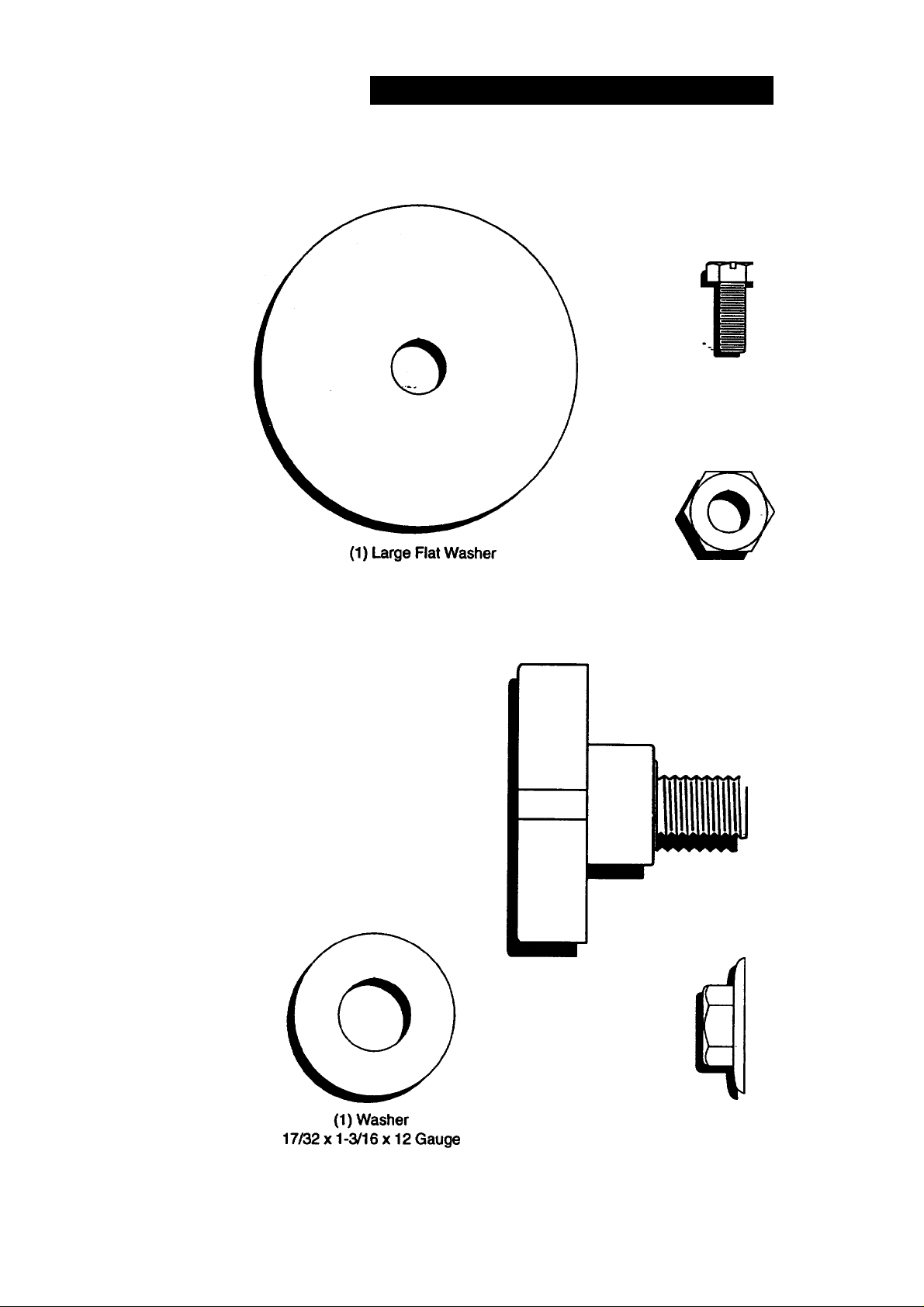
CONTENTS OF HARDWARE PACK
Parts Bag contents shown full size
(2) Sheet
Metal
Screws
#10-16x1/2
(1) Locknut
3/8-24
(1) Knob
wmm'
(1) Shoulder
Boll 5/16-18
Page 7
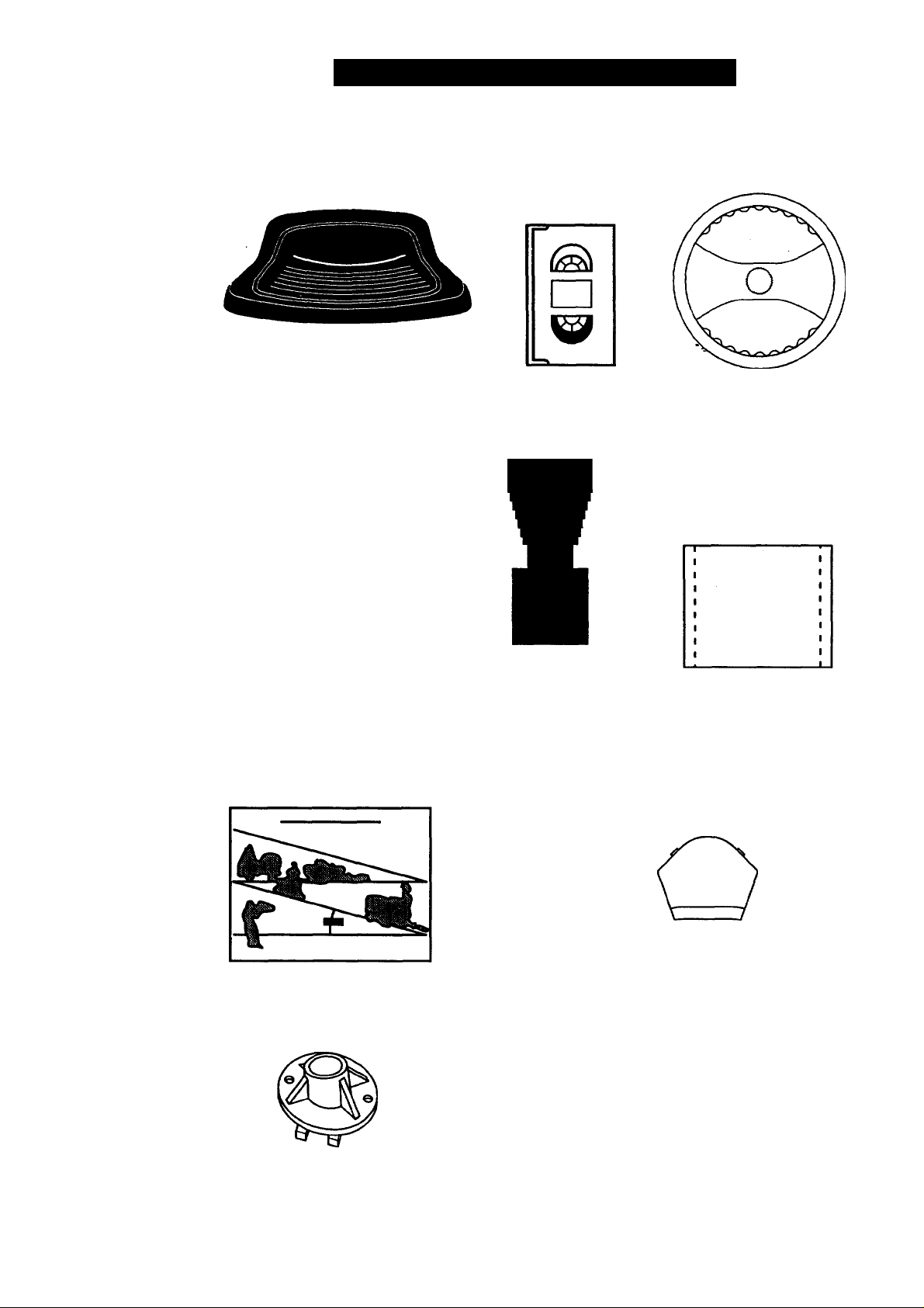
CONTENTS OF HARDWARE PACK
Parts packed separately in carton
Seat
Manual
Video
Cassette
Steering
Boot
Parts Bag contents not shown full size
Steering
Wheel
Parts Bag
Slope Sheet
Steering
Bushing
Steering
Wheel
Insert
(2) Keys
Steering Wheel
Adapter
Page 8
ASSEMBLY
Your new tractor has been assembled at the factory with exception of those parts left
unassembled for shipping purposes. To ensure safe and proper operation ef^ounifiaetor
all parts and hardware you assemble must be tightened securely. Use the correct tools
as necessary to insure proper tightness. Review the video cassette before you begin.
TOOLS REQUIRED FOR ASSEMBLY
A socket wrench set will make assembly
easier. Standard wrench sizes you need
are listed below.
(1) 9/16“ wrench (1) Utility knife
(2) 1/2" wrench (1) Pliers
(1) Phillips Screwdriver
(1) Tire pressure gauge
When right or left hand is mentioned in
this manual, it means, from your point of
view, when you are in the operating posi
tion (seated behind the steering wheel).
TO REMOVE TRACTOR FROM
CARTON
UNPACK CARTON
• Remove all accessible loose parts and
parts boxes from shipping carton (See
page 6).
• Cut, from top to bottom, along lines on
all four comers of shipping carton, and
lay panels flat.
• Check for any additional loose parts or
boxes and remove.
BEFORE ROLLING TRACTOR OFF SKID
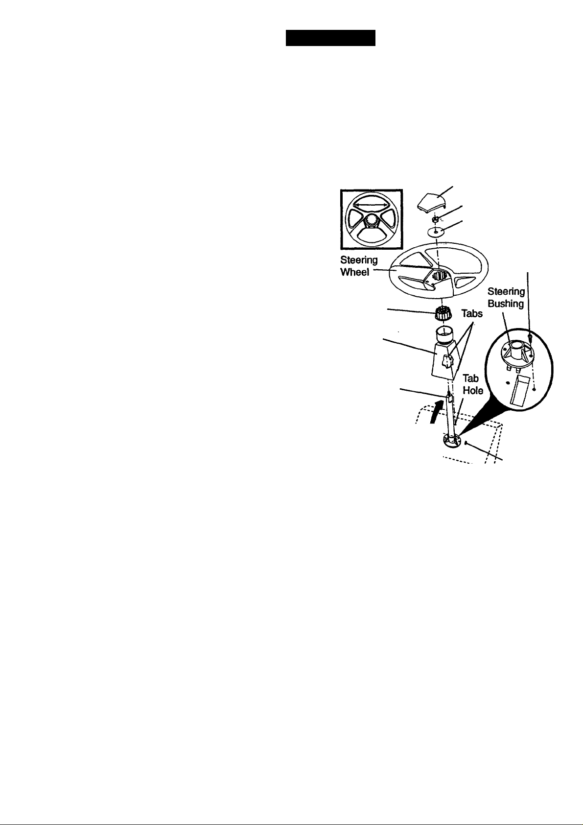
ATTACH STEERING WHEEL
• Slide the steering bushing over the
steering shaft.
• Raise steering shaft forward until screw
holes in dash line up with steering bush
ing. Install two (2) sheet metal screws
and tighten securely.
• Position steering boot over steering
shaft.
• Place tabs of steering boot over tab
slots in dash and push down to secure.
• Slide steering wheel adapter onto upper
steering shaft.
• Position front wheels of the tractor so
they are pointing straight forward.
• Position steering wheel so cross bars
are horizontal (left to right) and slide
onto adapter. •
• Assemble large flat washer and 3/8-24
locknut and tighten securely.
• Snap steering wheel Insert into center
of steering wheel.
• Remove protective materials from trac
tor hood and grill.
IMPORTANT: Check for and remove any
staples in skid that may puncture tires
where tractor is to roll off skid.
Insert
3/8-24 Locknut
Large Flat Washer
Steering Wheel
Adapter
Steering
Boot
Steering Shaft
(Assembly
Position)
Steering Shaft^
(Shipping ^
Position)
Tab Slot
TO ROLL TRACTOR OFF SKID
Operation section for ideation and
function of controis) '
• Press lift lever plunger and raise attach
ment lift lever to its highest position.
• Release parking brake by depressing
clutch/brake pedal.
• Place gearshift lever in neutral (N) posi
tion.
• Roil tractor fonvard off skid.
• Remove banding holding discharge
guard up against tractor.
8
Sheet
Metal
Screw
Page 9
HOW TO SET UP YOUR TRACTOR
CHECK BATTERY
• Lift seat pan to raised position and open
battery box door.
• If this battery is put into service after
month and year indicated on labei (iabei
iocated between terminals) charge bat
tery for minimurh of one hour, at 6-10
amps. (See "BATTERY" In Maintenance
section of this manual for charging
instructions).
Seat Pan
Label
Battery
Box Door
Terminal
Terminal
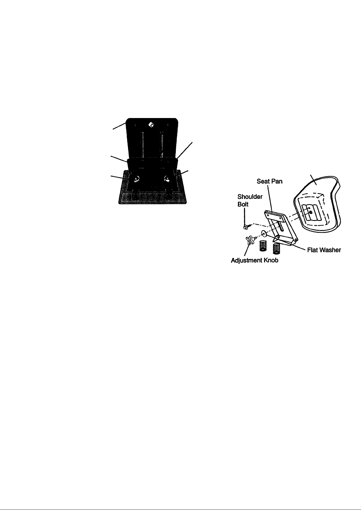
INSTALL SEAT
Adjust seat before tightening adjustment
knob.
____
• Remove cardboard pacKihg orTSeStt pan.
• Place seat on seat pan and assemble
shoulder bolt. Tighten shoulder bolt
securely.
• Assemble adjustment knob and flat
washer loosely. Do not tighten.
• Lower seat into operating position and
sit on seat.
• Slide seat until a comfortable position is
reached which allows you to press
clutch/brake pedal all the way down.
• Get off seat without moving its adjusted
position.
• Raise seat and tighten adjustment knob
securely.
Seat
Page 10

CHECK TIRE PRESSURE
The tires on your tractor were overinflated
at the factory for shipping purposes.
Correct tire pressure is important for best
cutting performance.
• Reduce tire pressure to PSI shown in
“PRODUCT SPECIFICATIONS” on
page 5 of this manual.
CHECK DECK LEVELNESS
For best cutting results, mower housing
should be properly leveled. See “TO
LEVEL MOWER HOUSING” In the
Service and Adjustments section of this
manual.
CHECK FOR PROPER POSITION OF
ALL BELTS ..
See the figures that are shown for replac
ing motion and mower blade drive belts in
the Service and Adjustments section of
this manual. Verify that the belts are rout
ed correctly.
CHECK BRAKE SYSTEM
After you learn how to operate your trac
tor, check to see that the brake is properly
adjusted. See “TO ADJUST BRAKE” in
the Service and Adjustments section of
this manual.
^CHECKLIST
PLEASE REVIEW THE FOLLOWIl^n
CHECKLIST:
✓ All assembly instructions have been
completed.
✓
No remaining loose parts In carton.
✓
Battery is properly prepared and
charged. (Minimum 1 hour at 6 amps).
Seat is adjusted comfortably and
tightened securely.
/
All tires are properly inflated. (For
shipping purposes, the tires were
overinflated at the factory).
Be sure mower deck is properly leveled
slde-to-slde/front-to-rear for best ^
cutting results. (Tires must be properly
inflated for leveling).
✓ Check mower and drive belts. Be sure
they are routed properly around pulleys
and inside all belt keepers.
✓ Check wiring. See that all connections
are still secure and wires are properly
clamped.
WHILE LEARNING HOWTO USE YOUR
TRACTOR, PAY EXTRA ATTENTION TO
THE FOLLOWING IMPORTANT ITEMS:
/ Engine oil is at proper level.
/ Fuel tank is filled with fresh, clean,
regular unleaded gasoline.
/ Become familiar with all controls - their
location and function. Operate them
before you start the engine.
/ Be sure brake system is in safe
operating condition.
10
Page 11
OPERATION
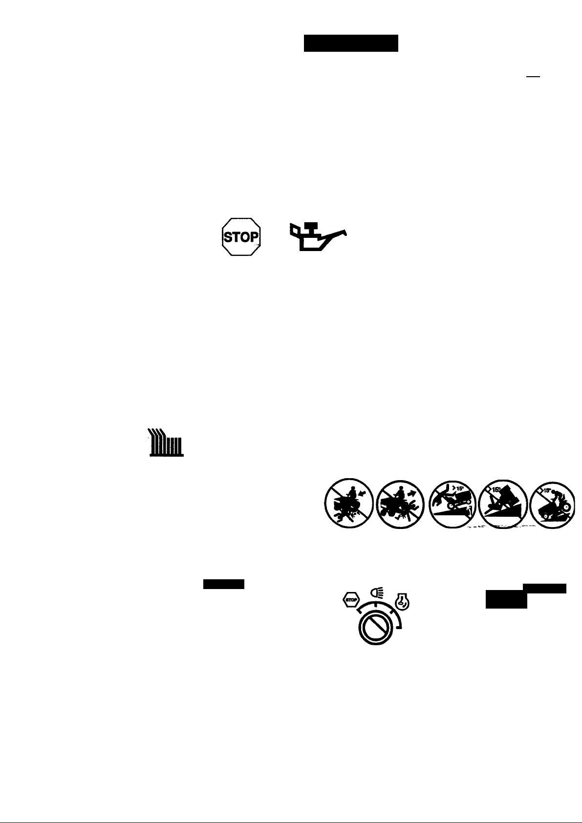
These symbols may appear on your tractor or in literature supplied with the oryj^cf -
Leam and understand their meaning.
a A
BATTERY
CAUTION OR
WARNING
REVERSE
©
ENGINE ON ENGINE OFF OIL PRESSURE
fi
FUEL
lu
L R N H L (®)|I
REVERSE NEUTRAL HIGH
;k
FORWARD FAST
li
CLUTCH LIGHTS ON *
©
DIFFERENTIAL
LOCK
PARKING BRAKE
LOCKED
LOW
•m
SLOW
©1
OVERTEMP
UGHT
UNLOCKED
PARKING BRAKE
MOWER LIFT
ATTACHMENT ATTACHMENT
CLUTCH ENGAGED CLUTCH DISENGAGED
DANGER, KEEP HANDS AND FEET AWAY
KEEP AREA CLEAR SLOPE HAZARDS
(SEE SAFETY RULES SECTION)
= ¿Sl
IGNITION
FREE WHEEL
(Automatic Models only)
11
Page 12
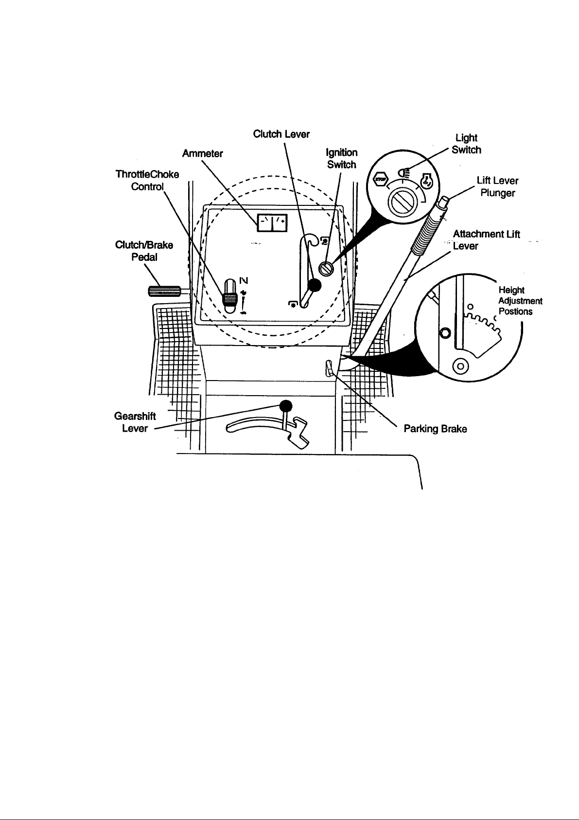
KNOW YOUR TRACTOR
READ THIS OWNER'S MANUAL AND SAFETY RULES BEFORE OPERATING YOUR
TRACTOR ,
Compare the Illustrations with your tractor to familiarize yourself with the location^ST"
various controls and adjustments. Save this manual for future reference.
Attachment
Our tractors conform to the safety standards of the American
National Standards Institute.
ATTACHMENT CLUTCH LEVER: Used
to engage the mower blades, or other
attachments mounted to your tractor.
LIGHT SWITCH: Turns the headlights on
and off.
THROTTLE/CHOKE CONTROL: Used
for starting and controlling engine speed.
CLUTCH/BRAKE PEDAL: Used for
declutching and braking the tractor and
starting the engine.
PARKING BRAKE: Locks clutch/brake
pedal into the brake position.
GEARSHIFT LEVER: Selects the speed
and direction of tractor.
ATTACHMENT LIFT LEVER: Used to
raise, lower, and adjust the mower deck or
other attachments mounted to your tractor.
LIFT LEVER PLUNGER: Used to release
attachment lift lever when changing its
position.
IGNITION SWITCH: Used for starting and
stopping the engine.
AMMETER: Indicates battery charging (+)
or discharging (-).
12
Page 13

The operation of any tractor can result in foreign objects thrown into the
eyes, which can result in severe eye damage. Always wear safety glass
es or eye shields while operating your tractor or performing.an^djust-
ments or repairs. We recommend a wide vision safety mask owr the
spectacles, or standard safety glasses.
HOW TO USE YOUR TRACTOR
Your tractor is equipped with an operator
presence sensing switch. When engine
is running, any attempt by the operator to
leave the seat without first setting the
parking brake will shut off the engine.
TO SET PARKING BRAKE
• Depress clutch/brake pedal Into full
“BRAKE” position and hold.
• Place parking brake lever in
“ENGAGED” position and release pres
sure from clutch/brake pedal. Pedal
should remain In “BRAKE” position.
Make sure parking brake will hold trac
tor secure.
Attachment Clutch Lever
Throttle/Choke
Control lever
Ciutch/Brake
Pedal 'Drive*
Position
'Disengaged*
Position
Brake*
Engaged' Position
Position
STOPPING
MOWER BLADES -
• To stop mower blades, move attach
ment clutch lever to “DISENGAGED”
position.
GROUND DRIVE -
• To stop ground drive, depress
clutch^rake pedal into full “BRAKE”
position.
• Move gearshift lever to neutral (N) posi
tion.
ENGINE -
• Move throttle control to slow position.
NOTE: Failure to move throttle control to
slow position and allowing engine to idle
before stopping may cause engine to
“backfire”.
• Turn ignition key to “OFF position and
remove key. Always remove key when
leaving tractor to prevent unauthorized
use.
• Never use choke to stop engine.
'Disengaged*
Position
Parking
Brake
'Engaged*
Position
_ Gearshift
Lever
IMPORTANT: Leaving the ignition switch
in any position other than “OFF will cause
the battery to be discharged (dead).
NOTE: Under certain conditions when
tractor is standing idle with the engine run
ning, hot engine exhaust gases may
cause “browning” of grass. To eliminate
this possibility, always stop engine when
stopping tractor on grass areas.
i^CAUTiON: Always stop tractor com
pletely, as described above, before leavingthe operator’s position; to empty grass
catcher, etc.
THROTTLE CONTROL
Always operate engine at full throttle.
• Operating engine at less than full throt
tle reduces the battery charging rate.
• Full throttle offers the best bagging and
mower performance.
TO MOVE FORWARD AND BACKWARD
The direction and speed of movement is
controlled by the gearshift lever.
• Start tractor with clutch/brake pedal
depressed and gearshift lever in neutral
(N) position.
• Move gearshift lever to desired posi
tion.
• Slowly release clutch/brake pedal to
start movement.
IMPORTANT: Bring tractor to a complete
stop before shifting or changing gears.
Failure to do so will shorten the useful life
of your transaxle - — —
TO ADJUST MOWER CUTTING HEIGHT
The position of the attachment lift lever
determines the cutting height.
• Grasp lift lever.
• Press plunger with thumb and move
lever to desired position.
The cutting height range is approximate
ly 1-1/2 to 4". The heights are measured
from the ground to the blade tip with the ,
engine not running. These heights are
approximate and may vary depending
upon soil conditions, height of grass and
types of grass being mowed.
13
Page 14

• For best cutting performance, grass
over 6 inches in height should be
mowed twice. Make the first cut rela
tively high; the second to desired
height.
TO OPERATE MOWER
Your tractor is Equipped with an operator
presence sensing switch. Any attempt by
the operator to leave the seat with the
engine running and the attachment clutch
engaged will shut off the engine.
• Select desired height of cut.
• Start mower blades by engaging attach
ment clutch control.
• TO STOP MOWER BLADES - disen
gage attachment clutch-control.
JIlCAUTION: Do not operate the mower
without either the entire grass catcher, on
mowers so equipped, or the discharge
guard in place.
Attachment
Lift Lever —
High Position
Attachment
Ciutch Lever
“Engaged"
Position
“Disengaged”
Position
Low
Position
Discharge
Guard
TO OPERATE ON HILLS ^
^CAUTION: Do not drive up or down
hills with slopes greater than 15° and do
not drive across any slope. A slope guide
at the back of your manual is provided for
your use.
• Choose the slowest speed before start
ing up or down hills.
• Avoid stopping or changing speed on
hills.
• If slowing is necessary, move throttle
control lever to slower position.
• If stopping is absolutely necessary,
push clutch/brake pedal quickly to brake
position and engage parking brake.
• Move gearshift lever to 1st gear. Be
^ sure you have allowed room for tractor
to roll slightly as you restart movement.
• To restart movement, slowly release
parking brake and clutch/brake pedal.
• Make all turns slowly.
TO TRANSPORT
• Raise attachment lift to highest position
with attachment lift control.
• When pushing or towing your tractor, be
sure gearshift lever is in neutral (N)
position. ,
• Do not push or tow tractor at more than
five (5) MPH.
NOTE: To protect hood from damage
when transporting your tractor on a truck
or a trailer, be sure hood is closed and
secured to tractor. Use an appropriate
means of tying hood to tractor (rope, cord,
etc.).
BEFORE STARTING THE ENGINE
CHECK ENGINE.OIL LEVEL
• The engine in your tractor has been
shipped, from the factory, already ifiiled
with summer weight oil.
• Check engine oil with tractor on level
ground.
• Remove oil fill cap/dipstick and wipe
clean, reinsert the dipstick and screw
cap tight, wait for a few seconds,
remove and read oil level, if necesseuy,
add oil until “FULL” mark on dipstick is
reached. Do not overfill.
• For cold weather operation you should
change oil for easier starting (See “OIL
VISCOSITY CHARr in the Mainten
ance section of this manual).
• To change engine oil, see the Mainten
ance section in this manual.
ADD GASOLINE
• Fill fuel tank. Use fresh, clean, regular
unleaded gasoline with a minimum of
87 octane. (Use of leaded gasoline will
increase carbon and lead oxide
deposits and reduce valve life). Do not
mix oil with gasoline.'Purchase^fuel in
quantities that can be used within 30
days to assure fuel freshness.
IMPORTANT: When operating in tempera
tures below 32°F(0°C), use fresh, clean
winter grade gasoline to help insure good
cold weather starting.
WARNING: Experience indicates that
alcohol blended fuels (called gasohol or
using ethanol or methanol) can attract
moisture which leads to separation and
formation of acids during storage. Acidic
gas can damage the fuel system of an
engine while in storage. To avoid engine
problems, the fuel system should be emp
tied before storage of 30 days or looger.
Drain the gas tank, start the engine and
let it run until the fuel lines and carburetor
are empty. Use fresh fuel next season.
Page 15

See Storage Instructions for additional
information. Never use engine or carbure
tor cleaner products in the fuel tank or per-
anent damage may occur.
2
kCAUTiON: Fill to bottom of gas tank
filler neck. Do not overfill. Wipe off any
spilled oil or fuel. Do not store, spill or use
gasoline near an open flame.
TO START ENGINE
When starting the engine for the first time
or if the engine has run out of fuel, it will
take extra cranking time to move fuel from
the tank to the engine.
• Sit on seat in operating position,
depress clutch^rake pedal and set
parking brake.
• Place gear shift lever in neutral (N) posi
tion.
• Move attachment clutch to “DISEN
GAGED” position.
• Move throttle control to choke position.
NOTE: Before starting, read the warm
and cold starting procedures below.
• Insert key into ignition and turn key
clockwise to “START" position and
release key as soon as engine starts.
Do not run starter continuously for more
than fifteen seconds per minute. If the
engine does not start after several
attempts, move throttle control to fast
position, wait a few minutes and try
again. If engine still does not start,
move the throttle control back to the
choke position and retry.
WARM WEATHER STARTING (50° F and
above)
• When engine starts, move the throttle
control to the fast positi^.
• The attachments and ground drive can
now be used. If the engine does not
accept the load, restart the engine and
allow it to warm up for one minute using
the choke as described above.
COLD WEATHER STARTING ( 50° F AND
BELOW)
• When engine starts, allow engine to run
with the throttle control in the choke
position until the engine runs roughly,
then move throttle control to fast posi
tion. This may require an engine warm
up period from several seconds to sev
eral minutes, depending on the temper
ature.
• The attachments can also be used dur
ing the engine warm-up period.
NOTE: At a high altitude (above 3000
feet) or in cold temperatures (below 32 F)
the carburetor fuel mixture may need to be
adjusted for best engine performance.
See “TO ADJUST CARBURETOR” in the
Service and Adjustments section of this
manual.
15
Page 16

MOWING TIPS
• Tire chains cannot be used when the
mower housing is attached to tractor.
• Mower should be properly leveled for
best mowing performance. See “TO
LEVEL MOWER HOUSING" In the
Service and Adjustments section of this
manual.
• The left hand side of mower should be
used for trimming.
• Drive so that clippings are discharged
onto the area that has been cut. Have
the cut area to the right of the machine.
This will result in a more even distribu
tion of clippings and more uniform cut
ting.
• When mowing large areas, start by turn
ing to the right so that clippings will dis
charge away from shrubs, fences, drive
ways, etc. After one or two rounds,
mow in the opposite direction making
left hand turns until finished
• if grass is extremely tali, it should be
mowed twice to reduce load and possi
ble fire hazard from dried clippings.
Make first cut relatively high; the second
to the desired height.
Do not mow grass when it is wet. Wet
grass will plug mower and leave unde
sirable clumps. Allow grasdcto dr^ufi,,^
before mowing.
Always operate engine at full throttle
when mowing to assure better mowing
performance and proper discharge of
material. Regulate ground speed by se
lecting a low enough gear to give the
mower the best cutting performance as
well as the quality of cut desired.
When operating attachments, select a
ground speed that will suit the terrain
and give best performance of the at
tachment being used.
r
r
r *
3
'
, J
( /
V
16
Page 17
MAINTENANCE
CUSTOMER RESPONSIBILITIES
MAINTENANCE SCHEDULE
nu. IN OATES
AS YOU COMPLETE
Check Brake Operation
Check Tire Pressure
Check Operator Preserfce and
Interlock Systems
Check for Loose Fasteners
SharpeiVReplace Mower Blades
Lubrication Chart
Check Battery Level
Clean Battery and Terminats/Recharge
Check Transaxle Cooling
Adjust Blade Belt(s)Tension....
A<qust Motion Drive Belt(s) Tension
Check Engine Oil Level
Change Engine Oil
Clean Air Filter
E
Clean Air Screen
N
G
Inspect Muffler/Spark Arrester
I
Replace Oil Filter (If equipped)
N
Clean Engine Cooling Fins
E
Replace Spark Plug
Replace Air Filter Paper Cartridge
Replace Fuel Filter
1 - Chang« mom often wh«n opomling uncter a haavy load or In high amblant tempaiatur««. S - If «qulppad with adKntabla ayatem.
2 - S«rvlc« mor« often whan oparaling In dirty or dua^ conditions. 6 - Not raquirad If aquippad with maintenanca-fr«« battery.
3-K aquippad with oil filter, Chang« 0* «vary SO hours. 7 - Tighten front arda pivot bolt to 35 IL-ti«. maximum.
✓ ✓
✓
✓
✓
✓ •/7 ✓
✓ 4
✓
✓
✓
✓ s
✓ s
✓
✓
•^.3 ✓
✓ 2
✓ 2
✓
^\.2
✓ a
✓
✓
✓ a
✓
✓
-
-
GENERAL RECOMMENDATIONS
The warranty on this tractor does not cover
items that have been subjected to operator
abuse or negligence. To receive full value
from the warranty, operator must maintain
tractor as instructed in this manual. Some
adjustments will need to be made periodi
cally to properly maintain your tractor.
All adjustments in the Service and
Adjustments section of this manual should
be checked at least once each season.
• Once a year you should replace the
spark plug, clean or replace air filter, and
check blades and belts for wear. A new
spark plug and clean air filter assure
proper air-fuel mixture and help your
engine run better and last longer.
BEFORE EACH USE
• Check engine oil level.
• Check brake operation.
• Check tire pressure.
• Check operator presence and interlock
systems for proper operation.
• Check for loose fasteners.
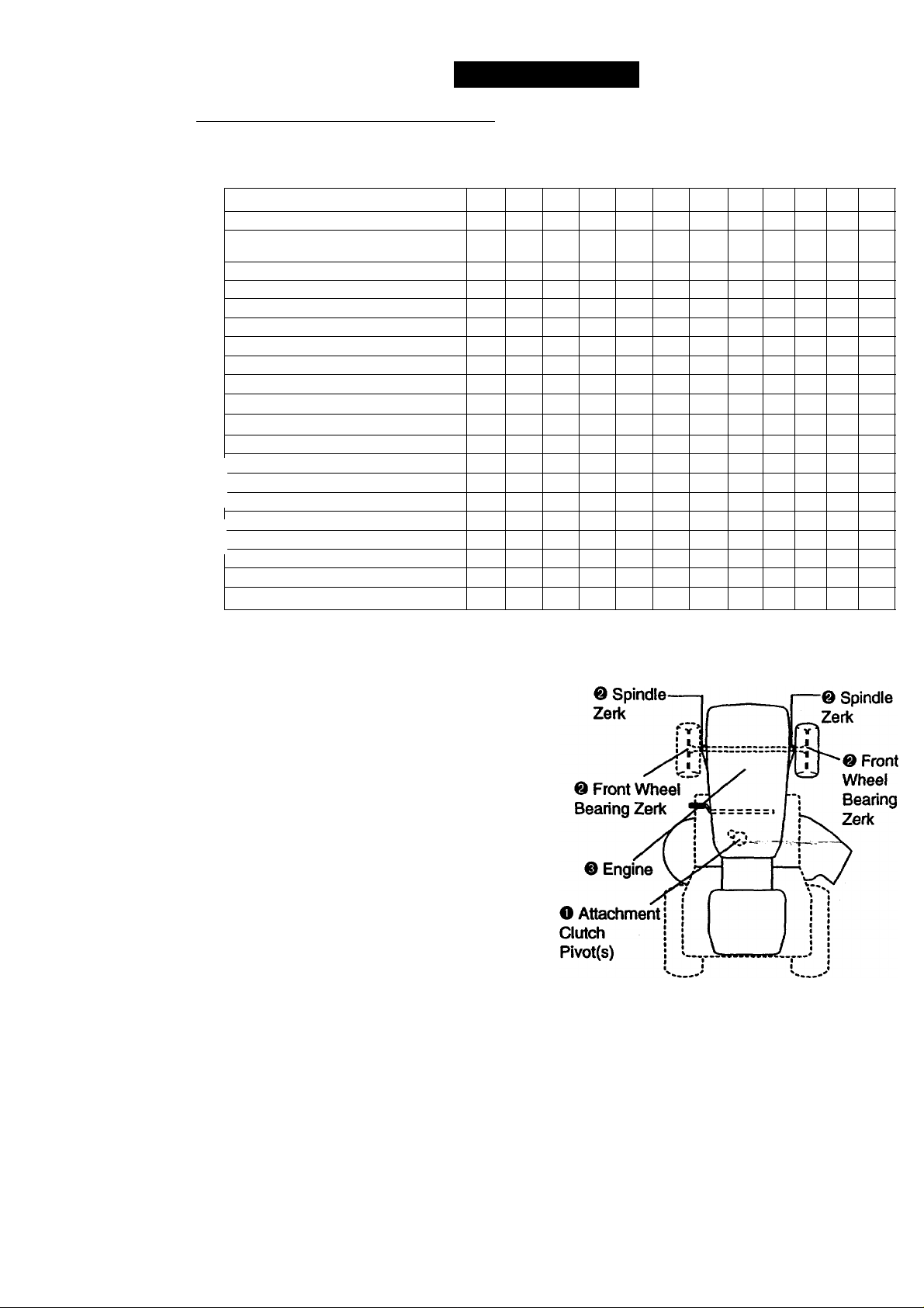
LUBRICATION CHART
O SAE 30 or 10w30 Motor OIL
& General Purpose Grease
© Refer to Maintenance “Engine" Section
IMPORTANT: Do not oil or grease the
pivot points which have special nylon bear
ings. Viscous lubricants will attract dust
and dirt that will shorten the life of the selflubricating bearings. If you feel they must
be lubricated, use only a dry, powdered
graphite type lubricant sparingly.
17
Page 18
TRACTOR
Always observe safety rules when per
forming any maintenance.
BRAKE OPERATION
if tractor requires more than six (6) feet
stopping distance at high speed in highest
gear, then brake must be adjusted. (See
TO ADJUST BRAKE" in the Service and
Adjustments section of this manual).
TIRES
• Maintain proper air pressure in all tires
(See “PRODUCT SPECIFICATIONS"
on page 5 of this manual).
• Keep tires free of gasoiine, oil, or insect
control chemicals which can harm rub
ber.
• Avoid stumps, stones, deep ruts, sharp
objects and other hazards that may
cause tire damage.
NOTE: To seal tire punctures and prevent
fiat tires due to slow leaks, tire sealant
may be purchased from your local parts
dealer. Tire sealant also prevents tire dry
rot and corrosion.
OPERATOR PRESENCE SYSTEM
Be sure that operator presence and inter
lock systems are working properly. If your
tractor does not function as described
below, repair the problem immediately.
• The engine should not start unless the
clutch/brake pedal is fully depressed
and attachment clutch control is in the
disengaged position.
• When the engine is running, any
attempt by the operator to leave the
seat without first setting the parking
brake should shut off the engine.
• When the engine is running and the
attachment clutch is engaged, any
attempt by the operator to leave the
seat should shut off the engine.
• The attachment clutch should never
operate unless the operator is in the
seat.
BLADE CARE
For best results mower blades must be
kept sharp. Replace bent or damaged
blades.
BLADE REMOVAL
• Raise mower to highest position to allow
access to blades.
• Remove hex bolt, lock washer and flat
washer securing blade.
• Install new or resharpened blade with
trailing edge up towards deck as shown.
IMPORTANT: To ensure proper assembly,
center hole in blade must align with star
on mandrel assembly.
• Reassemble hex bolt, locE^wa!#№^nd
flat washer in exact order as shown.
• Tighten bolt securely (27-35 Ft. Lbs.
torque).
IMPORTANT: Blade bolt is Grade 8 heat
treated.
Trailing Center Mandrel
Blade note
Lock Washer
Hex Bolt 'N. ^
(Grades)*
Rat Washer
*A Grade 8 heat treated bolt can be
Identified by six lines on the bolt head.
Assembly
Star
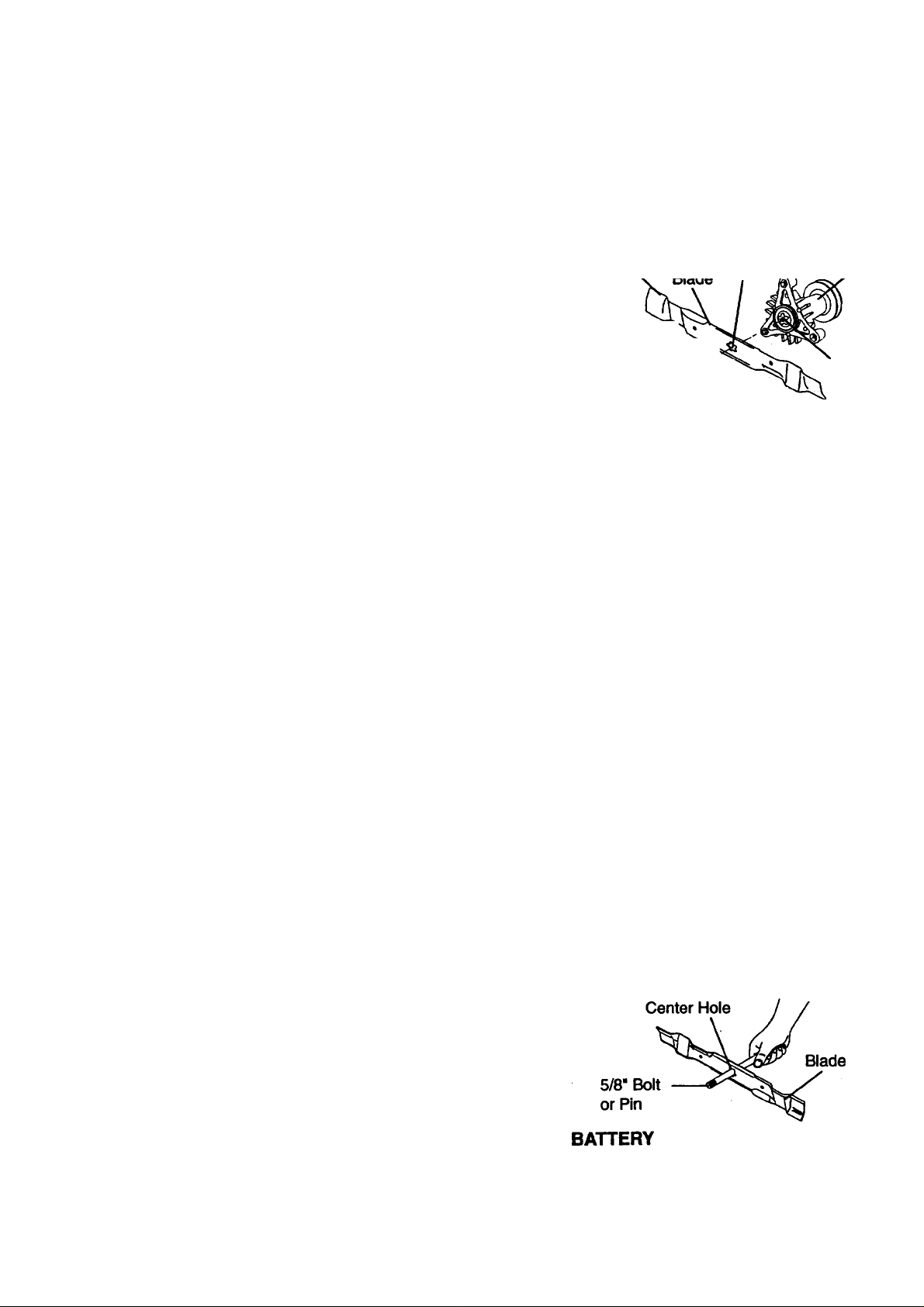
TO SHARPEN BLADE
NOTE: We do not recommend sharpening
blade, but if you do, be sure the blade is
balanced. ~
Care should be taken to keep the blade
balanced. An unbalanced blade will cause
excessive vibration and eventual damage
to mower and engine.
• The blade can be sharpened with a file
or on a grinding wheel. Do not attempt
to sharpen while it Is on the mower.
• To check blade balance, you will need a
5/8" diameter steel bolt, pin, or a cone
balancer. (When using a cone balancer,
follow the instructions supplied with bal
ancer).
NOTE: Do not use a nail for balancing
blade. The lobes of the center hole may
appear to be centered,-but-are-notr
• Slide blade onto an unthreaded portion
of the steel bolt or pin and hold the bolt
or pin parallel with the ground. If blade
is balanced, it should remain in a hori
zontal position. If either end of the blade
moves downward, sharpen the heavy
end until the blade is balanced.
Your tractor has a battery charging system
which is sufficient for normal use.
18
Page 19

However, periodic charging of the battery
with an automotive charger wilt extend its
life.
• Keep battery and terminals clean.
• Keep battery bolts tight.
• Keep small vent holes open.
• Recharge at 6-10 amperes for 1 hour.
TO CLEAN BATTERY AND TERMINALS
Corrosion and dirt on the battery and ter
minals can cause the battery to “leak”
power.
• Open battery box door.
• Disconnect BLACK battery cable first
then RED battery cable and remove
battery from tractor.
• Rinse the battery with plain water and
dry.
• Clean terminals and battery cable ends
with wire brush until bright.
• Coat terminals with grease or petroleum
jelly.
• Reinstall battery (See “REPLACING
BATTERY" In the SERVICE AND
ADJUSTMENTS section of this manu
al).
V-BELTS
Check V-belts for deterioration and wear
after 100 hours of operation and replace if
necessary. The belts are not adjustable.
Replace belts if they begin to slip from
wear.
Change the oil after every 25 hours of
operation or at least once a year if the
tractor is not used for 25 hours in one
year.
Check the crankcase oil level before start
ing the engine and after each eight (8)
hours of operation. Tighten oil fillcap/dipstick securely each time you check the oil
level.
TO CHANGE ENGINE OIL
Determine temperature range expected
before oil change. All oil must meet API
service classification SF, SG or SH.
• Be sure tractpr is on level surface.
• Oil will drain rnore freely when warm.
• Catch oil in a suitable container. _ ,
• Remove oil fill cap/dipstick. Be careful
not to allow dirt to enter the engine
when changing oil.
• Remove drain plug.
• After oil has drained completely, replace
oil drain plug and tighten securely.
• Refill engine with oil through oil fill dip
stick tube. Pour slowly. Do not overfill.
For approximate capacity see “PROID-
UCT SPECIFICATIONS” on page 5 of
this manual.
• Use gauge on oil fill cap/dipstick for
checking level. Be sure dipstick cap is
tightened securely for accurate reading.
Keep oil at “FULL” line on dipstick.
TRANSAXLE COOLING
Keep transaxle free from build-up of dirt
and chaff which can restrict cooling.
ENGINE
LUBRICATION
Only use high quality detergent oil rated
with API service classification SF, SG or
SH. Select the oil’s SAE viscosity grade
according to your expected operating tem
perature.
NOTE: Although multi-viscosity oils
(5W30,10W30 etc.) improve starting in
cold weather, these multi-viscosity oils will
result in increased oil consumption when
used above 32“F. Check your engine oil
level more frequently to avoid possible
engine damage from running low on oil.
SAE VISCOSITY GRADES
] I I
mr S3T 40*
TEMPERATURE RANGE ANTICtPATED BEFORE NEXT OIL CHANGE
I i
AIR FILTER
Your engine will not run property using a
dirty air filter. Clean the foam pre-cleaner
after every 25 hours of operation or every
season. Service paper cartridge every 100
hours of operation or every season,
whichever occurs first.
Service air cleaner more often under dusty
conditions.
• Remove knob(s) and cover.
TO SERVICE PRE-CLEANER
• Slide foam pre-cleaner off cartridge.
• Wash it in liquid detergent and water.
• Squeeze it dry in a clean cloth.
• Saturate it in engine oil. Wrap it in clean,
absorbent cloth and squeeze to remove
excess oil.
19
Page 20

• If very dirty or datnaged, replace pre
cleaner.
• Reinstall pre-cleaner over cartridge.
• Reinstall cover and secure with knob(s).
TO SERVICE CARTRIDGE
• Remove cartridge nut.
• Carefully remove cartridge to prevent
debris from entering carburetor. Clean
base carefully to prevent debris from
entering carburetor.
• Clean cartridge by tapping gently on flat
surface. If very dirty or damaged,
replace cartridge.
• Reinstall cartridge, nut, precleaner,
cover and secure with knob(s).
IMPORTANT: Petroleum solvents, such as
kerosene, are not to be usedto clean the
cartridge. They may cause deterioration of
the cartridge. Do not oil cartridge. Do not
use pressurized air to clean or dry car
tridge.
Cover
Knob
Cover
Foam
Pre-Cleaner
Cartridge
Nut
Paper
Cartridge
Base
CLEAN AIR SCREEN
Air screen must be kept free of dirt and
chaff to prevent engine damage from over
heating. Clean with a wire brush or com
pressed air to remove dirt and stubborn
dried gum fibers.
ENGINE COOLING FINS
Remove any dust, dirt or oil from engine
cooling fins to prevent engine damage
from overheating.
• Remove screws from blower housing
and lift housing and dipstick tube .
assembly off engine.
• Cover oil fill opening to prevent entry of
dirt.
• Use compressed air or stiff bristle brush
to thoroughly clean engine cooling fins.
• To reassemble, reverse above proce
dure.
MUFFLER
Inspect and replace.corroded muffler and
spark arrester (if equipped) as it could cre
ate a fire hazard and/or damage.
SPARK PLUGS
Replace spark plugs at the beginning of
each mowing season or after every 100
hours of operation, whichever occurs first.
Spark plug type and gap setting are
shown in “PRODUCT SPECIFICATIONS”
on page 5 of this manual.
IN-LINE FUEL FILTER
The fuel filter should be replaced once
each season. If fuel filter becomes
clogged, obstructing fuel flow to carbure
tor, replacement is required.
• With engine cool, remove filter and plug
fuel line sections.
• Place new fuel filter in position in fuel
line with arrow pointing towards carbu
retor.
• Be sure there are no fuel line leaks and
clamps are properly positioned.
• Immediately wipe up any spilled gaso
line.
Screws Blower Housing screws
DIpstickTube
A^embly
Engine Cooling Rns
CLEANING
• Clean engine, battery, seat, finish, etc.
of all foreign matter.
• Keep finished surfaces and wheels free
of all gasoline, oil, etc.
• Protect painted surfaces with automo
tive type wax.
We do not recommend using a garden
hose to clean your tractor unless the elec
trical system, muffler, air filter and carbure
tor are covered to keep water out.A/VaterLin engine can result in a shortened engine
life.
20
Page 21

SERVICE AND ADJUSTMENTS
AcAUTION: Before performing any service or adjustments: .
• Depress clutch/brake pedal fuiiy and set parking brake.
• Place gearshift lever in neutral (N) position.
• Place attachment clutch in “DISENGAGED” position.
• Turn ignition key “OFP and remove key.
• Make sure the blades and all moving parts have completely stopped.
• Disconnect spark plug wire from spark plug and place wire where it cannot come
in contact with plug.
TO REMOVE MOWER
Mower will be easier to remove from the
right side of tractor.
• Place attachment clutch in “DISEN
GAGED” position. ‘
• Move attachment lift lever fonward to
lower mower to its lowest position.
• Roll belt off engine pulley.
• Disconnect clutch rod from clutch lever
by removing retainer spring,
• Disconnect anti-swaybar from chassis
bracket by removing retainer spring.
• Disconnect suspension arms from rear
deck brackets by removing retainer
springs.
• Disconnect front links from deck by
removing retainer springs.
• Raise lift lever^o raise suspension
arms. Slide mower out from under trac
tor,
IMPORTANT: If an attachment other than
the mower deck is to be mounted on the
tractor, remove the front links.
TO INSTALL MOWER
• Raise attachment lift lever to its highest
position. .
• Slide mower under tractor with dis- ~
charge guard to right side of tractor.
• Lower lift lever to Its lowest position.
• Install mower in reverse order of
removal instructions.
21
Page 22

TO LEVEL MOWER HOUStNG
Adjust the mower while tractor is parked
on level ground or driveway. Make sure
tires are properly inflated (See “PROD
UCT SPECIFICATIONS"). If tires are
over or underinflated, you will not properly
adjust your mower.
SIDE-TO-SIDE ADJUSTMENT
• Raise mower to its highest position.
• At the midpoint of both sides of mower,
measure height from bottom edge of
mower to ground. Distance “A” on both
sides of mower should be the same or
within 1/4“ of each other.
• If adjustment is necessary, make adjust
ment on one side of mower only.
• To raise one side of mower, tighten lift
link adjustment nut on that side.
• To lower one side of mower, loosen lift
link adjustment nut on that side.
NOTE: Each full turn of adjustment nut
will change mower height about 1/8".
Bottom ^^ I—-—■—I ^ Bottom
of Curl r ^ I--«A 1 of Curl
equal in length. Both links should be
approximately 10-3/8“.
• If links are not equal in leagUi.^gyust'
one link to same length as other link.
• To lower front of mower loosen nut “P
on both front links an equal number of
turns.
• When distance “D” is 1/8“ to 1/2" lower
at front than rear, tighten nuts “P
against trunnion on both front links.
• To raise front of mower, loosen nut “P
from trunnion on both front links.
Tighten nut “E" on both front links an
equal number ojf turns.
• When distance “D” is 1/8" to 1/2" lower
at front than rear,, tighten nut “P against
trunnion on both front links.
• Recheck side-to-side adjustment.
Mandrel
Both Front Links Should be Equal in Length
Recheck measurements after adjusting.
-RONT-TO-BACK ADJUSTMENT
MPORTANT: Deck must be level side-to-
5lde. If the following front-to-back adjust-
nent is necessary, be sure to adjust both
ront links equally so mower will stay
evel side-to-side.
Ho obtain the best cutting results, the
newer housing should be adjusted so that
he front is approximately 1/8" to 1/2"
Dwer than the rear when the mower is in
;s highest position.
)heck adjustment on right side of tractor.
Measure distance “D” directly in front and
>ehind the mandrel at bottom edge of
newer housing as shown.
Before making any necessary adjust
ments, check that both front links are
Trunnion
Front Links Trunnion
TO REPLACE MOWER BLADE DRIVE
BELT (See Illustration Next Page)
The mower blade drive belt may be
replaced without tools. Park the tractor on
level surface. Engage parking brake.
BELT REMOVAL
• Remove mower from tractor (See “TO
REMOVE MOWER” in this section of
this manual).
• Work belt off both mandrel pulleys and
idler pulleys.
• Pull belt away from mower.
22
Page 23

BELT INSTALLATION
• Install new belt in reverse order of
removal.
• Make sure belt is in ail pulley grooves
and inside all belt guides.
• install mower in reverse order of
removal instructions.
Mandrel
Pulley
TO ADJUST BRAKE
Your tractor is equipped with an adjustable
brake system which is mounted on the
right side of the transaxle.
If tractor requires more than six (6) feet
stopping distance at high speed in high
est gear, then brake must be adjusted.
• Depress clutch/brake pedal and engage
parking brake.
• Measure distance between brake oper
ating arm and nut “A” on brake rod.
• If distance is other than 1-1/2", loosen
jam nut and turn nut “A” until distance
becomes 1-1/2". Retighten jam nut
against nut “A”.
• Road test tractor for proper stopping
distance as stated above. Readjust if
necessary. If stopping distance is still
greater than six (6) feet in highest gear,
further maintenance is necessary.
Contact your nearest authorized ser
vice center.
Idler
Pulleys
Mandrel
Pulley
TO REPLACE MOTION DRIVE BELT
Park the tractor on level surface. Engage
parking brake. For assistance, there is a
belt installation guide decal on bottom side
of left footrest.
• Remove mower (See “TO REMOVE
MOWER” In this section of this manual.)
• Remove belt from stationary idler and
clutching idler.
• Pull belt slack toward rear of tractor.
Remove belt upwards from transaxle
pulley by deflecting belt keepers.
• Pull belt toward front of tractor and
remove downwards from around engine
pulley.
• Install new belt by reversing above pro
cedure.
With Parking Brake "Engaged"
23
Page 24

TO ADJUST STEERING WHEEL ALIGN
MENT
If steering wheel crossbars are not hori
zontal (left to right) when wheels are posi
tioned straight forward, remove steering
wheel and reassemble per instructions in
the Assembly section of this manual.
FRONT WHEEL TOE-IN/CAMBER
The front wheel toe-in and camber are not
adjustable on your tractor. If damage has
occurred to affect the front wheel toe-in or
camber, contact your nearest authorized
service center.
TO REMOVE WHEEL FOR REPAIRS
• Block up axle securely.
• Remove axle cover, retaining ring and
washers to allow wheel removal (rear
wheel contains a square key - Do not
lose).
• Repair tire and reassemble.
• On rear wheels only: align grooves in
rear wheel hub and axle. Insert square
key.
• Replace washers and snap retaining
ring securely in axle groove.
• Replace axle cover.
NOTE: To seal tire punctures and prevent
flat tires due to slow leaks, tire sealant
may be purchased from your local parts
dealer. Tire sealant also prevents tire dry
rot and corrosion.
Washers
Retaining Ring
Axle
Cover.,^
Square Key
(Rear Wheel Only)
TO START ENGINE WITH A WEAK
BATTERY
ACAUTION: Lead-acid batteries gener
ate explosive gases. Keep sparks, flame
and smoking materials away from batter
ies. Always wear eye protection when
around batteries.
if your battery is too weak to start the
engine, it should be recharged. (See
“BATTERY" in the MAINTENANCE sec
tion of this manued).
If “jumper cables” are used for emergency
starting, follow this procedure:
IMPOOTANT: Your tractor Is equipped
with a 12 volt negative grounded system.
The other vehicle must also be a 12 volt
negative grounded system. Do not use
your tractor battery to start other vehicles.
TO ATTACH JUMPER CABLES -
• Connect each end of the RED cable to
the POSITIVE (+) terminal of each bat
tery, taking care not to short against
chassis.
• Connect one end of the BLACK cable to
the NEGATIVE (-) terminal of fully
charged battery.
• Connect the other end of the BLACK
cable to good CHASSIS GROUND,
away from fuel tank and battery.
TO REMOVE CABLES, REVERSE
ORDER-
• BLACK cable first from chassis and
then from the fully charged battery.
• RED cable last from both batteries.
Positive
Terminal
Chassis
Charged
Battery
Positive Termiiial
Negative
Terminal
Cables
Negative
Terminal
REPLACING BATTERY
ACAUTION: Do not short battery ter
minals by allowing a wrench or any
other object to contact both terminals
at the same time. Before connecting
battery, remove metal bracelets, wristwatch bands, rings,etc.
Positive terminal must be connected
first to prevent spari<ing4rom acciden
tal grounding.
• Lift seat pan to raised position and open
battery box door.
• Disconnect BLACK battery cable first
then RED battery cable and carefully
remove battery from tractor.
• Install new battery with terminals in
same position as old battery.
• First connect RED battery cable to posi
tive (+) terminal with hex bolt and keps
nut as shown. Tighten securely.
• Connect BLACK grounding cable to
negative (-) terminal with remaining hex
bolt and keps nut. Tighten securely.
• Close battery box door.
24
Page 25

Seat Pan
Battery Box
Door
Keps Nut-^-.::^
Positive (Red) Cable Negative (Black) Cable
TO REPLACE HEADLIGHT BULB
• Raise hood.
• Pull bulb holder out of the hole in the
backside of the griil.
• Replace bulb in holder and push bulb
holder securely back into the hole in the
backside of the grill.
• Close hood.
INTERLOCKS AND RELAYS
Loose or damaged wiring may cause your
tractor to run poorly, stop running, or pre
vent It from starting.
• Check wiring. See electrical wiring dia
gram in the Repair Parts section of this
manual.
Hex Bolt
ENGINE
Maintenance, repair, or replacement of the
emission control devices and systems,
which are being done atthecusUwaereexpense, may be performed by any non
road engine repair establishment or indi
vidual. Warranty repairs must be per
formed by an authorized engine manufac
turer's service outlet.
TO ADJUST THROTTLE CONTROL
CABLE
The throttle control has been preset at the
factory and adjustment should not be nec
essary. Check adjustment as described
below before loosening cable. If adjust
ment is necessary, proceed as follows:
• With engine not running, move throttle
control lever from slow to choke posi
tion. Slowly move lever from choke to
fast position.
• Check that holes “A” in governor controi
lever and hole in governor plate line-up.
If holes "A” are not aligned, loosen
clamp screw and move throttle cable,
until holes are aligned. Tighten clamp
screw securely.
Governor
Control Lever
Governor
Control Plate
TO REPLACE FUSE
Replace with 30 amp automotive-type
plug-in fuse. The fuse holder is located
behind the dash.
TO REMOVE HOOD AND GRILL
ASSEMBLY
• Raise hood.
• Unsnap headlight wire connector.
• Stand in front of tractor. Grasp hood at
sides, tilt toward engine and lift off of
tractor.
• To replace, reverse above procedures.
Headlight
Wire
Hood
Connector
25
Page 26

TO ADJUST CARBURETOR
NOTE: The carburetor on this engine is
low emission. It is equipped with an idle
fuel adjusting needle with a limiter cap,
which allows some adjustment within the
limits allowed by the cap. Do not attempt
to remove the limiter cap. The limiter cap
cannot be removed without breaking the
adjusting needle.
The carburetor has been preset at the fac
tory and adjustment should not be neces
sary. However, minor adjustment may be
required to compensate for differences in
fuel, temperature, altitude or load. If the
carburetor does need adjustment, proceed
as follovy^;
In general, turning idle mixture valve in
(clockwise) decreases the supply of fuel to
the engine giving a leaner fuel/air mixture.
Turning the idle mixture valve out
(counterclockwise) increases the supply of
fuel to the engine giving a richer fuel/air
mixture.
IMPORTANT: Damage to the needle valve
and the seat in carburetor may result if
screw is turned in too tight.
PRELIMINARY SETTING -
• Air cleaner assembly must be assem
bled to the carburetor when making car
buretor adjustments.
• Be sure the throttle control cable is
adjusted properly (see above).
• While still holding throttle lever against
idle speed screw, turn idle mixture valve
full travel clockwise then counterclock
wise until engine runs rod^hi TtSValve
to a point midway between those two
positions. Release throttle lever.
ACCELERATION TEST-
• Move throttle control lever from slow to
fast position. If engine hesitates or dies,
turn idle mixture valve out (counter
clockwise) 1/8 turn. Repeat test and
continue to adjust, if necessary, until
engine accelerates smoothly.
High speed stop is factory adjusted. Do
not adjust—damage may result.
IMPORTANT: Never tamper with the
engine governor, which is factory set for
proper engine speed, overspeeding the
engine above the factory high speed set
ting can be dangerous, if you think the
engine-governed high speed needs
adjusting, contact your nearest authorized
service center, which has proper equip
ment to make any necessary adjustments.
Idle Speed
Screw
Throttle
Lever
FINAL SETTING-
• Start engine and allow to warm for five
minutes. Make final adjustments with
engine running and shift/motion control
lever in neutral (N) position.
• Move throttle control lever to slow posi
tion. With finger, rotate and hold throttle
lever against idle speed screw. Turn Idle
speed screw to attain 1750 RPM.
26
Page 27

STORAGE
Immediately prepare your tractor for stor
age at the end of the season or if the trac
tor will not be used for 30 days or more.
AcaUTION: Never store the tractor with
gasoline in the tank inside a building
where fumes may reach an open flame or
spark. Allow the engine to cool before stor
ing in any enclosure.
TRACTOR
Remove mower from tractor for winter
storage. This will allow you to clean it thor
oughly. Remove all dirt, grease, leaves,
etc. Store in a clean, dry area.
• Clean entire tractor (See “CLEANING” in
the Maintenance section of this manual).
• Inspect and replace belts, if necessary
(See belt replacement instructions in the
Service and Adjustments section of this
manual).
• Lubricate as shown in the Maintenance
section of this manual.
• Be sure that all nuts, bolts and screws
are securely fastened. Inspect moving
parts for damage, breakage and wear.
Replace if necessary.
• Touch up ail rusted or chipped paint sur
faces; sand lightly before painting.
BATTERY
• Fully charge the battery for storage.
• After a period of time in storage, battery
may require recharging.
• To help prevent corrosion and power
leakage during long periods of storage,
battery cables should be disconnected
and battery cleaned thoroughly (see “TO
CLEAN BATTERY AND TERMINALS” in
the Maintenance section of this manual).
• After cleaning, leave cables disconnect
ed and place cables where they cannot
come in contact with battery terminals.
• If battery is removed from tractor for
storage, do not store battery directly on
concrete or damp surfaces.
ENGINE
FUEL SYSTEM
IMPORTANT: It Is important to prevent
gum deposits from forming in essential fuel
system parts such as carburetor, fuel filter,
fuel hose, or tank during storage. Also,
experience indicates that alcohol blended
fuels (called gasohol or using ethanol or
methanol) can attract moistureHMiNeh'
leads to separation and formation of acids
during storage. Acidic gas can damage the
fuel system of an engine while in storage.
• Drain the fuel tank.
• Start the engine and let It run until the
fuel lines and carburetor are empty.
• Never use engine or carburetor cleaner
products in the fuel tank or permanent
damage may occur.
• Use fresh fuel next season.
NOTE: Fuel stabilizer is an acceptable
alternative in minimizing the formation of
fuel gum deposits during storage. Add sta«
biiizer to gasoline in fuel tank or storage
container. Always follow the mix ratio
found on stabilizer container. Run engine
at least 10 minutes after adding stabilizer
to allow the stabilizer to reach the carbure
tor. Do not drain the gas tank and carbure
tor if using fuel stabilizer.
ENGINE OIL
Drain oil (with engine warm) and replace
with clean engine oil. (See “ENGINE” in
the Maintenance section of this manual).
CYLINDER(S)
• Remove spark plug(s).
• Pour one ounce of oil through spark
plug hole(s) into cylinder(s).
• Turn ignition key to “START position for
a few seconds to distribute oil.
• Replace with new spark piug(s).
OTHER
• Do not store gasoline from one season
to another. ' ^ ~
• Replace'your gasoline can if it starts to
rust. Rust and/or dirt in your gasoline
will cause problems.
• If possible, store your tractor indoors
and cover it to give protection from dust
and dirt.
• Cover your tractor with a suitable pro
tective cover that does not retain mois
ture. Do not use plastic. Plastic cannot,
breathe, which allows condensation to
form and cause your tractor to rust.
IMPORTANT: Never cover tractor while
engine and exhaust areas are still warm.
27
Page 28

TROUBLESHOOTING CHART
PROBLEM
Will not start
Hard to start
CAUSE
• Out of fuel.
• Engine not “CHOKED"
property.
• Engine flooded. • Wait several minutes before
• Bad spark plug.
• Dirty air filter.
• Dirty fuel filter.
• Water in fuel.
• Loose or damaged wiring. • Check all wiring.
• Carburetor out of adjust
ment.
• Engine valves out of
adjustment.
• Dirty air filter.
• Bad spark plug.
• Weak or dead battery.
• Dirty fuel filter.
• Stale or dirty fuel.
• Loose or damaged wiring.
• Carburetor out of adjust
ment.
• Engine valves out of
adjustment.
CORRECTION
• Fill fuel tank. ''
• See TO START ENGINE” In
Operation section.
attempting to start.
• Replace spark plug.
• Clean/replace air filter.
• Replace fuel filter.
• Drain fuel tank and carbure
tor, refill tank with fresh
gasoline and replace fuel fil
ter.
• See To Adjust Carburetor"
in Service and Adjustments
section.
• Contact an authorized ser
vice center.
• Clean/replace air filter.
• Replace spark plug.
• Recharge or replace battery.
• Replace fuel filter.
• Drain fuel tank and refill with
fresh gasoline.
• Check all wiring.
• See To Adjust Carburetor"
in Service and Adjustments
section.
• Contact an authorized ser
vice center.
Engine will not turn
over
Engine clicks Dut
will not start • Corroded battery termi
• Clutch/brake pedal not
depressed.
• Attachment clutch is
engaged.
• Weak or dead battery.
• Blown fuse.
• Corroded battery termi
nals.
• Loose or damaged wiring.
• Faulty ignition switch.
• Faulty solenoid or starter.
• Faulty operator presence
switch(es).
• Weak or dead battery.
nals.
28
• Depress clutch/brake pedal.
• Disengage attachment—
clutch. .
• Recharge or replace battery.
• Replace fuse.
• Clean battery terminals.
• Check all wiring.
• Check/replace ignition
switch.
• Check/replace solenoid or
starter.
• Contact an authorized ser
vice center.
• Recharge or replace battery.
• Clean battery terminals.
Page 29

TROUBLESHOOTING CHART
PROBLEM
Engine clicks but
will not start (cont’d)
Loss of power
CAUSE
CORRECTION
• Loose or damaged wiring. • Check all wiring.
• Faulty solenoid or starter.
• Check/replace solenoid or
starter.
• Cutting too much • Set in “Higher Cuf posigrass/too fast.
• Throttle in “CHOKE” posi
tion/reduce speed.
• Adjust throttle control.
tion.
• Build-up of grass, leaves
and trash under mower.
• Dirty air filter.
• Low oil level/dirty oil.
• Faulty spark plug.
- --
• Dirty fuel filter.
• Stale or dirty fuel.
• Clean underside of mower
housing.
• Clean/replace air filter.
• Check oil level/change oil.
• Clean and regap or change
sparkplug.
• Replace fuel filter.
• Drain fuel tank and refill with
fresh gasoline.
• Water in fuel. *
• Drain fuel tank and carbure
tor, refill tank with fresh gaso
line and replace fuel filter.
• Spark plug wire loose.
• Connect and tighten spark
plug wire.
• Dirty engine air
• Clean engine air screen/fins.
screen/fins.
• Dirty/clogged muffler.
• Loose or damaged wiring.
• Carburetor out of adjust
ment.
• Clean/replace muffler.
• Check all wiring.
• See “To Adjust Carburetor” in
Service and Adjustments
section.
• Engine valves out of
adjustment.
• Contact an authorized ser
vice center.
Excessive vibration
Engine continues to
run when operator
leaves seat with at
tachment clutch
engaged
Poor cut - uneven
• Worn, bent or loose blade.
• Bent blade mandrel.
• Loose/damaged part(s).
• Faulty operator-safety
presence control system.
• Worn, bent or loose blade.
• Mower deck not level.
• Buildup of grass, leaves,
and trash under mower.
• Bent blade mandrel.
29
• Replace blade. Tighten blade
bolt.
• Replace blade mandrel.
• Tighten Jo_osapart(s).
Replace damaged parts.
• Check wiring, switches and
connections. If not
corrected, contact an autho
rized service center.
• Replace blade. Tighten blade
bolt.
• Level mower deck.
• Clean underside of mower
housing.
• Replace blade mandrel.
Page 30

TROUBLESHOOTING CHART
PROBLEM
Poor cut - uneven
(cont’d)
Mower blades will
not rotate
Poor grass dis
charge
CAUSE
Clogged mower deck vent
holes from buildup of
grass, leaves, and trash
around mandrels.
Obstruction in clutch
mechanism.
Wom/damaged mower
drive belt.
Frozen idler pulley.
Frozen blade mandrel.
Engine speed too slow.
Travel speed too fast.
Wet grass.
Mower deck not level.
Low/uneven tire air pres
sure.
Worn, bent or loose blade.
Buildup of grass, leaves
and trash under mower.
Mower drive belt worn.
Blades improperly
installed.
Improper blades used.
Clogged mower deck vent
holes from buildup of
grass, leaves, and trash
around mandrels.
CORRECTION
Clean around mandrels to
open vent holes.
Remove obstruction.
Replace mower drive belt.
Replace idler pulley.
Replace blade mandrel.
Place throttle control in
“FAST” position.
Shift to slower speed.
Allow grass to dry before
mowing.
Level mower deck.
Check tires for proper air
pressure.
Replace/sharpen blade.
Tighten blade bolt.
Clean underside of mower
housing.
Replace mower drive belt.
Reinstall blades sharp edge
down.
Replace with blades listed in
this manual.
Clean around mandrels to
open vent holes.
Headlight(s) not
working (if so
equipped)
Battery will not
charge
Engfhe “backfires”
when turning
engine “OFF
Switch is “OFF.
Bulb(s) burned out.
Faulty light switch.
Loose or damaged wiring.
Blown fuse.
Bad battery cell(s).
Poor cable connections.
Faulty regulator (if so
equipped).
Faulty alternator.
Engine throttle control not
set at “SLOW”
position for 30 seconds
before stopping engine.
30
Turn switch “ON”. _
Replace bulB(s)r
Check/replace light switch.
Check wiring and connections.
Replace fuse.
Replace battery.
Check/clean all connections.
Replace regulator.
Replace alternator.
• Move throttle control to
“SLOW” position and allow
to idle for 30 seconds before
stopping engine.
Page 31

31
Page 32

32
Page 33

SCHEMATIC
TRACTOR - - MODEL NUMBER 917.270512
IGNITION SWITCH
posmoN
OFF
RUN/UGHT B-4-L A + Y
RUN
START
CIRCUIT “MAKE"
G + M + L
B-fL NONE
B + L + S
NONE
NONE
to O
SOLENOID
CLUTCH/BRAKE
(PEDAL UP)
WHTTE
SEAT SWITCH
(NOT OCCUPIED)
cj
(OPTIONAL)
-c
CHARQINQ SYSTEM OUTPUT
SAMP DC O 3600 RPM
IGNITION
UNIT
___
28 VOLTS AC MM. • 3600 RPM
(CHARGING SYSTEM DISCONNECTED)
NOTE
YOUR TRACTOR IS
EQUIPPED WITH A SPECIAL
ALTERNATOR SYSTEM.
THE LIGHTS ARE NOT
CONNECTED TO THE
BATTERY. BUT HAVE THEIR
OWN ELECTRICAL SOURCE.
BECAUSE OF THIS. THE
BRIGHTNESS OF THE LIGHTS
WILL CHANGE WITH ENGINE
SPEED. AT IDLE THE LIGHTS
WILL DIM. AS THE ENGINE IS
SPEEDED UP. THE LIGHTS
WILL BECOME THEIR BRIGHTEST.
NON-REMOVABLE
CONNECTIONS
WIRING INSULATED CUPS
NOTE: IF WIRING INSULATED CLIPS WERE REMOVED FOR
SERVICING OF UNIT. THEY SHOULD BE REPLACED TO
PROPERLY SECURE YOUR WIRING.
SPARK
n PLUG
W GAP W
(2 PLUGS ON
TWIN CYL. ENGINES)
REMOVABLE
CONNECTIONS
r
m
33
Page 34

ELECTRICAL
REPAIR PARTS
TRACTOR - - MODEL NUMBER 917.270512
34
Page 35

ELECTRICAL
TRACTOR - - MODEL NUMBER 917^70512
KEY
NO.
16 153664
19
20
21
22 4152J
24
25 146147
26 108824X
27
28 4207J
29
30 140301
31 124211X
32
33 109310X
40 156442
41
42
43 145673
44
45
52 141940
70 140422
PART
NO.
1
144925 Battery 12 Volt 25 AMP
2 74760412
8 156417
STD551125 Washer Lock 1/4
-73350400
136850
4799J
73510400
121305X
141226
71110408
131563
73640400
121433X
DESCRIPTION
Bolt Hex Hd 1/4-20unc X 3/4
Case Battery
Switch Interlock Push-In
Nut Jam Hex 1/4-20 Unc
Harness Socket Light W/4152J
Bulb Light #1156
Cable Battery 6ga 11' red
Cable Battery 6 Ga W/16 Wir red
Fuse 30 AMP Auto Green
NutKepsHex 1/4-20 Unc
Cable Ground 6ga 12* black
Switch Plunger Nc Gray
Switch Ign 4 pos
Nut Ignition
Cover Sw Ignition
Key Ign Molded Craftsman, Delta
Harness Man Cl Am Hm 97
Bolt BIk Hex 1/4-20unc x 1/2
Cover Terminal Red
Solenoid
Nut Keps BIk Hex 1/4-20 Unc
Ammeter Rectangular 6 AMP
Protection Wire Loop
Harness Engine, Duai 14 OHV
NOTE: All component dimensions give in U.S. inches
1 inch = 25.4 mm
35
Page 36

TRACTOR - - MODEL NUMBER 917.270512
CHASSIS AND ENCLOSURES
36
Page 37

TRACTOR -
CHASSIS AND ENCLOSURES
MODEL NUMBER 917.270512
KEY
NO.
10
11
13
14
15
16
17
18
19
21
22
24
25
26
28 140137
29
30
31
33
34
35
37
38
39 139887
54 161464
140
145 156524
161
- -
1
2
3
4
5
6
7
8
9
PART
NO.
160393
140356
17490612
STD551025
155272
155924X012
126842X
155138
161914X012
STt)533710
155927
155934X010
17490608
74180512
STD541431
154988X558
126938X
17521312
122933X
124479X
STD523710
19131312
STD541437
124029X
157584X558
136619
145244X558
145243X558
STD533707
17490508
139886
158418
161547
5479J
DESCRIPTION
Chassis
Drawbar Stretch
Screw Thdtol 3/8-16 x 3/4 Ty-tt
Washer 13/32 X 3/4 X16 Ga
Bumper Dash Hood
Saddle Slkscr
Shield HL Hood Kohi/Dia Engine
Clip Retainer Slide On
Ds^ Slkscr 1-pc
Bolt Rdhd Sqnk 3/8-16unc X1
Panel Dash LH
Panel Slkscr Dash RH
Screw Thdrol 3/8-16 x 1/2 Ty-tt
Screw Mach TRHD 5/16-18 unc x 3/4
Nut Keps 5/16-18 Unc
Hood Asm Pnt Slope Weld Ms-558
Bumper Hood
Screw Sltd Hex Hd W/PI Vlfasher
Rivet Ratchet Nylon
Washer Nylon BIk 28 x 75 x 19
Bolt Rn Hex 3/8-16 unc x 1 Gr. 5
Washer 13/32 X13/16 x 12 Ga
Nut Hex Lock W/lns. 3/8-16 Unc
Grille Black
Lens Headlight Bar Clear
Fender Pnt LT W/o Shift
Bracket Fender RepI 109873x
Footrest Pnt Lh
Footrest Pnt Rh
Bolt Rdhd Sht Sqnk 3/8-16 x 3/4
Screw Thdrol. 5/16-18x1/2
Bracket Asm Pvt LH MWR Rear
Bracket Asm Pvt RH MWR Rear
Screw Hex Wshd 8-18x7/8
Bracket Suspension Front
Rod Pivot Chassis/Hood
Extrusion Bumper
Plug Button BIk 359 Dia Choke
NOTE: All component dimensions give ¡n U.S. inches
1 inch = 25.4 mm
37
Page 38

GROUND DRIVE
TRACTOR - - MODEL NUMBER 917.270512
/;
-ÍÍ' 1 ! '’y'^ --i* I
' i ^r-T s'* i.!'ti ^
* * -'J *■'
'<• I '
38
Page 39

GROUND DRIVE
TRACTOR - - MODEL NUMBER 917^70512
KEY PART
NO. NO.
—
1
2 146682
123666X
3
4 12000028
121520X
5
6 17490512
7
162240
8 131679
10 STD561210
11 105701X
12 19151216
13
74550412
14
STD551125
18 STD523710
19 STD541437
21 106933X
22
130804
24
STD541237
25 106888X
26 STD551037
27
STD561210
28 145204
29
124236X
30 130807
31 127275X
32
STD523107
34 155071
35
120183X
36
STD551062
37
STD571810 Pin Roll 3/16x1"
38
123674X
39 STD523727
40
4470J
41
154777
42
19131312
47
127783
DESCRIPTION
Ttansaxle (See Breakdown)
Peeiless Model 206-506B
Spring Return Brake T/a Zinc
Pulley Transaxle 18/20" tires
Ring Retainer # 5100-62
Strap Torque 30 Degrees
Screw Thdrol 5/16-18 x 3/4 TYT
Bracket Saddle Shift T/a
Rod Shf Sdl LY/YT Str BIk Zinc
Pin Cotter 1/8x1 Cad
V№isher Ptete Shf 388 Sq Hole
Washer 15^ x 3/4 x 16^
Bolt 1/4-28unf Gf8 W/Patch
Washer Lock Hvy Helical 1/4
Bolt Fin Hex
Nut Lock Hex W/lns. 3/8-16
Unc
Knob Rd 1/2-13 Piste Thds BIk
Rod Brake BIk Zinc 26 840
Nut Hex Jam 3/8-16 Unc
Spring Rod Brake 2 00 Zinc
Washer 13/32 x 13/16 x 16 Ga
Pin Cotter 1/8 X 3/4 Cad
Rod Brake Parking Lt/Yt
Cap Brake Parking Red
Bracket Mtg Transaxle
Keeper Belt LH LT14 Ga
Bolt Hex Hd 5/16-18unc x 3/4
Shaft Asm Pedal Foot
Bearing Nylon BIk 629 Id
Washer21/32x1 x16Ga
Pulley Idler Flat
Bolt Fin Hex 3/8-16unc x 2-3/4
Spacer Split 395 x 59 Bzp
Keeper BÌsIt Idler
V№tsher 13/32 x 13/16 x 12 Ga
Pulley Idler V Groove Plastic
KEY
NO.
46 154407
49 123205X
50
STD523715
STD541437
51
52
STD541431
53
10571OX
54
2751R
55
105709X
56
STD523712
57
130801
56
127274X
59
140312
61
17490612
62
8883R
63
140186
64
71170764
65
STD551143
66
154778
70
134683
72
19132012
74
137057
75
121749X
76
STD581075
77
123583X
78
121748X
79 2228M
96
4497H
112
19091210
113
127285X
116
72110610
145
74490540
148
159103 Spacer
149
122052X
150
150935 ' Bushing Nylon Coliered
151
NOTE:
19133210
PART
NO.
Ail component dimensions give in U.S.
inches 1 inch = 25.4 mm
DESCRIPTION
Bellcrank Clutch Gm Drv StI
Retainer Belt Style Spring
Bolt Hex Hd 3/8-16unc x 1-1/2
NutCrownbek 3/8-16 UNC
Nut Crown Lock 5/16-18
Link Clutch 7 66
Clip Fuel Line 13/32 Mtg. Hole
--.Spring Return Clutch 6 75
Bolt Fin Hex 3/8-16 unc x 1-1/4
V-BeltGdDrive9500
keeper Belt RH LT Pnt/zinc 16g
Keeper Belt Centerspan
Screw ThdrolS/8-16 x 3/4 Ty-tt
Cover Pedal BIk Round
Pulley Eng Cl Mech 38deg
LT/YT
Bolt Hex 7/16-20 X 4 Gr 5
Washer Lock Hvy Hid Spr 7/16
Keeper Belt Engine ~
Guide Beit Mower Drive RH
Washer 13/32 x 1-1/4 x 12 Ga
Spacer Axle
Washer 25/32 x 1 1/4 x 16 Ga
E-ring #5133-75
Key Square 2 0 x 1845/1865
Washer 25/32 x 1-5/8 x 16ga
Key Woodruff #9 3/16x3/4
Retainer Spring 1”
Washer 9/32 x 3/4 x 10 Ga
Strap Torque Lh Lt
Bolt Rdhd Sq Neck 3/8-16 x
1.25
Bolt Hex FLGHD 5/16-18Gr.5
Spacer Retainer PM Mower
Washeiri3?32 x2 X iO Ga
'?Q
Page 40

STEERING ASSEMBLY
TRACTOR - - MODEL NUMBER 917.270512
~38
40
40
Page 41

STEERING ASSEMBLY
TRACTOR - - MODEL NUMBER 917.270512
KEY
NO. NO.
to 156438
11
13 154779
15
17 156545
18 57079
19 124035X
20
22 71200410
23 127501
25 154406
26 126847X
27 136874
28 19131416
29
30
32
36 155099
37 152927
38 139769
39
40 STD541537 Locknut Center 3/8-24 Unf
41 104820X
42 124417X
43
46
47 6855M Fitting Grease
62 156593
65 66
67 74781044
68 154429
PART
DESCRIPTION
1
139768
154427
2
3 156483
4 157473
5 6266H
6 121748X
7 19272016
12000029
8
9 3366R
10040600
73901000
126684X
17490612 Screw Thdrol 3/8-16 x 3/4 TY-TT
STD561210 Pin Cotter 1/8 X 3/4 Cad
130465 Rod Tie Wire Form 19.75 Mech
19133808 Washer 13/32 x 2-3/8 x 8 Ga.
121749X
121232X
154780
154404
Wheel Steering Opp Sears BIk
Axle Asm Front Lt
Spindle Asm Lh
Spindle Asm Rh
Washer Thiust .75x1.230
Washer 25/32 x 1-5/8 x 16 Ga.
Washer 27/32 x 1-1/4 x 16 Ga.
RingKIip #T5304-75
Bearing Col Strg Bik
Draglink Extended Stamped
Washer Lock Hvy HIcI Spr 3/8
Bearing Axle
Locknut Flange 5/8-11 UNC
Shaft Asm Strg 5/8 x 15.19 Lt
Washer Thrust .515 x .750 x .033
Support Shaft
Washer Shim 1/4 x 5/8 x.062
Screw Hex Socket 1/4-20 x 5/8
Shaft/Vsm Pitman
Bracket Steering
Bushing Link Drag Bik LR
Gear Sector 22 Teeth
Washer 13/32 x 7/8 x 16 Ga.
Bushing Strg. 5/8 ID Dash
Screw
Cap Wheel Steer Opp Sears USA
Adaptor Wheel Strg. .640/.635ld
Boot Shaft Steering Craftsman
Washer 25/32 x 1-1/4 x 16 Ga.
Cap Spindle Fr Top Bik
Steering Assembly
Spacer Axle
Bearing Arm Pittman
Bolt Rn Hex 5/8-11 UNC x 2-3/4
Brace Axle
NOTE: All component dimensions given in U.S. inches
1 inch = 25.4 mm
41
Page 42

ENGINE
TRACTOR - - MODEL NUMBER 917.270512
29
OPTIONAL EQUIPMENT
Spark Arrester
23
42
Page 43

ENGINE
TRACTOR - - MODEL NUMBER 917.270512
KEY
NO.
13
14
15
16
23
29
31
32
33
35
37 137040
38
40
44
46
62
72 71070512
78
81 128861
PART
NO.
162144
1
17720410
2
3
4 137352-
165291
13280324 Nipple Pipe 3/8 Npt x 3*
13200300
STD551237
159880
137180
109202X
158990
123487X
17490512
124028X
17490412
19091416
STD551131
17490620
DESCRIPTION
Control Th/ch RH BIk P(fl 1510
Screw Hex Thd Cut 1/4-20x5/8 T
Engine (See Breakdown)Briggs, Model No 287707-1255-El
Muffler ExhLTB&S14HP 1C OHV
Gasket Eng 1 313 Id Tin Plated
Elbow Std 90 Degree 3/8-18 Npt
Washer Lock Ext Tooth 3/8
Shield Browning/Debris Guard
Kit Spark Arrestor (Flat Scm)
Tank Fuel Front 1 25
Cap Asm Fuel Sears Vented
Clamp Hose BIk
Screw Thdrol 5/16-18x3/4 TYT
Line Fuel 20*
Plug Oil Drain (Order From Engine Manufacturer)
Bushing Snap Nyl BIk Fuel Line
Screw Hexwsh Thdrol 1/4-20 x 3/4
Washer 9/32 x 7/8 x 16 ga
Washer Lock Hvy Hid Spr 5/16
Screw Hex Hd Cap 5/16-18 X 3/4
Screw Thdrol 3^-16x1-1/4 TYTT
Nut Flange 1/4-20 Starter Nut
NOTE: All component dimensions given in U.S. inches
1 inch = 25.4 mm
43
Page 44

SEAT ASSEMBLY
TRACTOR - - MODEL NUMBER 917.270512
KEY
NO.
1 140122
2 140551
3
4
5
6
7
8
9
10
11
12
PART
NO.
STD523710
19131610
145006
STD541437
124181X
17490616
19131614
155925
120068X ,
121246X
DESCRIPTION
Seat
Bracket Pvt St
Bolt Rn Hex 3/8-16unc X1
Washer Rat 13/32 X1 X10 Ga
Clip Push-In Hinged
Locknut Hex W/Wsh 3/B-16
Spring Seat Cprsn 2 250 BIk Zi
Screw Thdrol 3/8-16 X1 Ty-tt
V\feisher 13/32 X1 X14 Ga
Pan Seat
Knob Seat 1/2-13 Unc BIk
Bracket Mounting Switch
44
KEY
NO.
13
14
15
16
17
21
22
24
25
NOTE:
PART
NO.
121248X
72050412
134300
121250X
123976X
153236
STD541431
19171912
127018X
Ail component dimensions given in U.S. inches
1 inch = 25.4 mm
DESCRIPTION
Bushing Snap BIk Nyl 50 Id
Bolt Rdhd Sht Nk 1/4-20x1-1/2
Spacer Split 28x 96 Yel Zinc
Spring Cprsn 1 27 Bik Pnt
Nut Lock 1/4 Lge Rg Gr 5 Zinc
Bolt ShkJ 5/16-18 Unc
Nut Lock Hex “W/lns 5/16-18Washer 17/32 X1-3/16 X12 Ga
Bolt Shoulder 5/16-18X62
Page 45

DECALS
TRACTOR - - MODEL NUMBER 917.270512
14 6
KEY
NO.
10
11
PART
NO.
156867
1
165393
2
163990 Decal Hood RH
3
163991
4
133179
5
133644 Decal Maint Cust Sears
6
163204
9
149516
156439
WHEELS & TIRES
KEY
DESCRIPTION
Decal Dash Inst Oper English
Decal HP Engine
Decal Hood LH
Decal Mower QC System
Domesti
Decal Fender Craftsman White
Decal Battery Dngr/Psn Eng
Acme . -
Decal Danger Fender Eng/span
NO.
12
13
14 163249
15
21
KEY PART
NO. NO.
10
11
16
- . •
- -
1
2
3
4
5
6
7
8
9
PART
NO.
4900J
146046
160396
163209
131265
157199
138311
165428
165429
59192
65139
106222X
59904
106732X427
278H
9040H
106108X427
124635X
7152J
104757X
144334
DESCRIPTION ^
Decal Clutch/brake English
Decal V-Belt Dr Sch Tractor
Decal Panel Dash 6sp 42"
Decat V-Belt Sch
Decal Fender Sd 6/42
Decal Lightbox
Pad Footrest
Decal Handle Lft Height Adjust
Manual Owners English
Manual Owners Spanish
DESCRIPTION
Cap N^lue Tire
Stem Value
Tire F Ts 15 X 6 0 - 6 Seivice
Tube Inner Front #35060
Rim Asm 6*front White Sen/ice
Fitting Grease
Bearing Flange
Rim Asm 8*rear White Service
Tire R Ts 18x9 5-8 Senrice
Tube Rear 9 5X8 Senrice
Cap Axle BIkl 50X1 00
Sealant, Tire (10 oz. tube)
NOTE: All component dimensions given in U.S. inches
1 indr = 25.4 mm
45
Page 46

LIFT ASSEMBLY
TRACTOR - - MODEL NUMBER 917.270512
46
Page 47

LIFT ASSEMBLY
TRACTOR - - MODEL NUMBER 917.270512
KEY
NO.
12
13
15
16
17
18 73680800
20
31
32 73540600
NOTE: All component dimensions given in U.S. inches
PART
NO.
1 159460
159474 Shaft Asm Lift
2
105767X
3
12000002
4
19211621
5
120183X
6
125631X Grip Handle Ruled BIk
7
122365X Button Plunger Red
8
11 139865
139866
STD624008
127218 Link Front
73350800
130171 Tmnnion BikZinc
19 139868
163552
140302
1 inch = 25.4 mm
DESCRIPTION
Wire Asm Inner/Sprg W/jslungerLT
Pin Groove 1 500 Zinc
E Ring #5133-62
Washer Pltd 21/32 X1 X 21ga
Bearing Nylon BIk 629 Id
Link Lift LH
UnkUftRH
Retainer Spring
Nut Jam Hex 1/2-13 Unc
Nut Crownlock 1/2-13unc
Arm Suspension Rear
Retainer Spring Zinc
Bearing Pvt Lift Spherical
Nut Crownlock 3/8-24
A~f
Page 48

MOWER DECK
J« 77 ^7
TRACTOR - - MODEL NUMBER 917.270512
19
---
Sf
48
Page 49

MOWER DECK
TRACTOR - - MODEL NUMBER 917.270512
KEY
NO.
10 140296
11
12
13 137645
14 128774
15 110485X
16
17
18
19
20
21
22
23
24
25 123713X
26
27
28
29
30
31
32
33
34
35
36
37
40
41
43
44
45
46
PART
NO.
164961
1
STD533107
2
3 138017
4
138440
5
STD624008
6 130832
8 850857
9 STD551137
134149
129895
140329
72110610
72140505
132827
159770
STD541431
134753
131267
105304X
110452X
130968
19111016
131491
157722
129963
153535
137266
STD533717
133835
131494
19131316
STD541437
133551
140083
140088
STD624003
137729
DESCRIPTION
Mower Housing
Bolt
Bracket Assembly,Sway Bar,
Front
Bracket Assembly, Sway Bar
Retainer Spring
Arm, Suspension, Rear
Bott, Hex 3/8-24 x 1.25 Gr. 8
Washer, Lock
Washer, Hardened
Blade, Mulching
Bearing, Ball'
Shaft Assembly, Mandrel,
Vented (Includes Key No. 6)
Housing, Mandrel, Vented
Bearing, Ball, Mandrel
Stripper, Vented Mower Deck
Bolt, Carriage 3/8-16x1-1/4
BolL Carriage 5/16-18x5/8
Boft, Shoulder
Baffle, Vortex
Nut Crownlock 5/16-18 UNC
Stiffener Bracket
BrackeL Deflector
Cap, Sleeve
Spring, Torsion, Deflector
Nut, Push
Shield, Deflector
Washer 11/32 x 5/8 x 16 Ga.
Rod, Hinge
Screw Thdrol Washer Head
Washer, Spacer
Pulley, Mandrel
Nirt, Toplock, Ranged
Bolt
Fastner, Christmas Tree
Pulley, Idler, Rat
Washer 13/32 x 13/16 x 16 Ga.
Nut Crownlock 3/8-16 UNC
Rod, PivoL with Nibs
Rod, Clutch, Secondary, w/Nibs
Guard, Mandrel, L.H.
Retainer
Screw, Thd. Roll 1/4-20 x 5/8
KEY
NO.
48
133944
49
155066
50
131340
51
STD541410
52
139888
53
131845
54
133943
55
155046
56
122052X
58
140086
59
141043
67
162113
68
144200
71
142427
72
131870
73 127847
74
121748X
75
12000029
76
128903
77
127845
78
160571
79
127498
80
153701
81
73350600
82
142028
83
120958X
84
156084
85
72140620
92
STD541437
128
132
141
NOTE:
153390
19132203
6266H
--
130794
- -
164963
All componen!
1 inch = 25.4 mm
PART
NO.
DESCRIPTION
Washer, Hardened
Roller Assembly. Cam Foltower
Bolt, Shoulder #10-24 Grade 5
Locknut
Bolt, Shoulder 5/16-18 UNO
Arm /tesembly, Pad, Brake
Washer, Hardened
Arm, Idler
Spacer, Retainer
Spring, Torsion Brakes
Gtjard, TUV Idler
Knob Custom Oval
V-Belt
Rod, Clutch, Primary, with Nibs
Spring, Return
Arm, Qutch, Secondary
Washer 25/32 x 1-5/8 x 16 Ga.
Ring, Klip
Bolt, Shoulder 3/8-16 UNC x
1.44
Keeper, Spring
Lever Asm. Clutch Pri Plm
STLT
Bushing, Large, Brass
Spring, Mower Ciutch
Nut, Hex Jam 3/8-16 Unc
Trunnion, Adj.
Washer Sintered
Keeper Belt Icfler
Bolt Carriage 3/8-16x2-1/2
Nut
Washer Felt
Spacer, Washer 13/321.D. x 1-
3/8 0.D.X1/4
Washer Thrust .75x1.230
Mandrel Assembly (Includes
Key Numbers 8-10,12-15,31
and 32).
Mower Deck, Complete
(Standard Deck, Order
Separately Mulcher Plate and
Gauge Wheel Components,
Key Nos. 101-106 and 111-121)
49
Page 50

TRACTOR - - MODEL NUMBER 917.270512
PEERLESS TRANSAXLE - - MODEL NUMBER 206-508B
0-27
®—2SC •—-71
C%/y « - 1
-^1A ^
i "'i. /
\ .37,,
39,
,41A
70y 45
42
50
Page 51

TRACTOR - - MODEL NUMBER 917.270512
PEERLESS TRANSAXLE - - MODEL NUMBER 206-508B
REF
NO.
25A 792177 Screw 1/4-20X1-3/8*
PART
NO.
772147 Transaxle Cover
1
780086A Neede Bearing 5/8*
2
770128
3
776395
4
776409 Output Shaft
5
778364
6
778369
6A
7 778330
792180 Shift Key
8
792047
8A
784352
9
10 784378
778334
11
12 778309
13 778368
778367 Bevel Pinion (13 teeth) (Ind. 56
14
778370
15
786188 Drive Pin
17
786102 Spacer
18
792077
20
21 792078
22 792079
792073A Screw 1/4-20x1-1/4*
25
26 792125
27 792035
28 788040
780072
29
29A 780160
29B
29C 780199
31A 780195
35A 780197 Flanged Bushing 3/4* 900
780051
30 780108
31 780001 Washer (.056 wide) 83 778338
32 788083 Oil Seal 5/8* 150
34 780194 Bushing 157 788088
35 780193 Flanged Bushing 180
36 790075
37 790007
38 799021 Brake Pad (pkg of 2)
39 786026
40
792076A
DESCRIPTION NO. NO. DESCRIPTION
Transaxle Case
Countershaft 43
Spur Gear (38 teeth) 45
Spur Gear (15 teeth) 46 786086 Brake Lever Bracket
Spur Gear (11 teeth) 47 774690 Axle (11-15/16* long)
Woodruff. Key #9
Shift Collar
Shift Rod & Fork
Bevei Gear (30 teeth)
Input Bevel Pinion (13 teeth) 53 778350
Bevel Gear (13 teeth) (Incl. 14) 54 778346
13)
Ring Gear (43 teeth)
Bail 5/16* dia
Set Screw 3/8-16x3/8*
Spring
Retaining Ring (pkg of 2)
Retaining Ring
Retaining Ring
Washer
Washer
Thrust Washer (.762 ID)
/^nti-Rotation Washer
Washer teeth)
(USE AS NEEDED) 85
Flat Washer (.062 wide)
Brake Disk
Brake Pad Plate
Dowel Pin
Flat Washer
REF
41A 790079 Brake Lever
42A
71B 788092
PART
792073A
42
792085A
792075
44 790025 Brake Pad Holder
786066
48 774691
49 778356
778338
50
51 778354
52 778352 Spur Gear (19 teeth)
778355
57 778337
778353
58
59 778351
60 778349
61 778345
65 780189
776422 Input Shaft
66
67 776396
69 792170
786187
70
71 788069 Square Cut Ring
76 780090
77 788078A Inverted Retaining Ring
792144
79
82 778333
792154 Oil Rll Plug
87 788089
788093A Liquid GaskeTRtV Silicone
730229A Gear Oil 80W90
—
Parts must be ordered from Tecumseh Products Co.
NOTE:: All component dimensions given ki U.S. incfi
1 inch = 25.4 mm
Screw 1/4-20x1-1/4*
Screw 1/4-20x2-1/4*
Locknut 5/16-24
Spacer
Axle (16-1/2* long)
Spur Gear (29 teeth) ^
Spur Gear (27 teeth)
Spur Gear (23 teeth)
Spur Gear (16 teeth)
Spur Gear (15 teeth)
Spur Gear (11 teeth)
Spur Gear (13 teeth)
Spur Gear (17 teeth)
Spur Gear (21 teeth)
Spur Gear (24 teeth)
Spur Gear (25 teeth)
Washer
Shifter & Brake Shaft
Retaining Ring
Spacer .890
“O’Ring
Washer
Spring
Bevei & Spur Gear (30 & 13
Spur Gear (27 teeth)
Oil Seal a^16*
Oil Seal 3/4*
Replacement 206-508B
Transaxle
____
51
Page 52

TRACTOR - - MODEL NUMBER 917.270512
BRIGGS & STRATTON ENGINE-MODEL NUMBER 287707, TYPE NUMBER 1255-El
52
Page 53

TRACTOR - - MODEL NUMBER 917.270512
BRIGGS & STRATTON ENGINE-MODEL NUMBER 287707, TYPE NUMBER 1255-El
127 138 106 987 95 117 634
^ p 0 O
* REQUIRES SPECIAL TOOLS
TO INSTALL. SEE REPAIR
INSTRUCTION MANUAL.
53
Page 54

TRACTOR - - MODEL NUMBER 917.270512
BRIGGS & STRATTON ENGINE-MODEL NUMBER 287707, TYPE NUMBER 1255-El
54
Page 55

TRACTOR - - MODEL NUMBER 917.270512
BRIGGS & STRATTON ENGINE-MODEL NUMBER 287707, TYPE NUMBE§1255-E1
Page 56

TRACTOR - > MODEL NUMBER 917.270512
BRIGGS & STRATTON ENGINE-MODEL NUMBER 287707, TYPE NUMBER 1255-E
KEY PART
NO. NO.
496412
1
399265
2
391086
3
494238
4
495858
5
272614
7
495735
8
27803
9
94621
10
281246
11
271916
12
271997
271996
13
94728
94239
15
495162
16
94196
291675
20
94624
22
492326
23
24
222698
495860
25
495977
495978
495979
495854
26
495852
495851
495855
263129
27
498319
28
494504
29
495490
32 94695
32A 94648
495856
33
495857
34
262811
35
224502
37
224641
40
262411
45
496884
46
272465
51
52 272569
DESCRIPTION
Cylinder Assembly
Bering, Cylinder
•Seal, Oil
Base, Engine
Head, Cylinder
***Gasket, Cylinder Head
Breather Assembly
•Gasket, Valve Cover
Screw, Sems
Tube, Breather
•Gasket, Crankcase Cover,
l/B^"-
•Gasket, Crankcase Cover,
.005’
•Gasket, Crankcase Cover,
.009”
Screw, Cylinder Head
Plug, Oil Drain
Crankshaft
Timing Gear Key
•Seal, Oil
Screw, Sems, Base Mounting
Flywheel and Ring Gear
Assembly, Magneto
Key, Fly>^eel
Piston Assembly, Standard Size
Piston Assembly, .01 O'
Oversize
Piston Assembly, .020”
Oversize
Piston Assembly, .OSO*
Oversize
Ring Set, Piston, Standard Size
Ring Set, Piston. .010” Oversize
Ring Set, Piston, .020” Oversize
Ring Set, Piston, .030” Oversize
Lock, Piston Pin
Pin Assy., Piston, Standard Size
Rod Assembly, Connecting
Rod Assembly, Connecting,
.020” Undersize Crankpin Bore'
Screw, Hex Vlfasher Head, 157/64
Screw, Hex Washer Head, 15/8
Wilve, Exhaust
Wilve, Intake
Spring, Valve
Guard, Flywheel
Retainer, Valve Spring
TappeL Valve
Gear, Cam
"••Gasket, Carburetor
(Carburetor to EBiow)
•"Gasket Carburetor
(Elbow to Cylinder)
KEY PART
NO. NO.
53
94637
73
224948
75
225136
78
94626
281346
93
95
94098
495800
98
104
105
106
108
111
117
118
121
123
125
127
130
131
133
137
138
141
142
164
166
171
187
188
192
201
209
216
219
224
225
227
230
232
238
240
265
NOTE:
231789
231855
231854
224540
262719
232118
232119
498030
499233
94913
499153
224539
494379
494381
281165
281164
495931
232117
214047
94555
281051
492790
94627
492160
262767
260695
262766
490815
495611
94729
495157
493935
94927
262785
262836
394358
221535
All component dimensions given in U.S. inches
1 inch = 25.4 mm
included In Gasket Set (495993) -
Included In Carburetor Kit (499233)
Included In Both Gasket Set (495993) arxl
Valve Overhaul Kit (495992)
Included In Gasket Set (495993), Carburetor Ki
(499233) and Carburetor Gasket Set (494385)
DESCRIPTION
Stud, Carburetor Mounting
Screen, Rush Rotating
Washer, Spring
Screw, Sems
Bushing, Throttle Shaft
••Screw, Throttle
Screw, Idle Speed
••Pin, Float Hinge
••Valve Float
"Seat, Inlet Wilve
Valve, Choke .
Spring, Choke
Jet Main (Std.)
Jet Main (Hi-Alt.)
Valve, Needle
Carburetor Overhaul Kit
Screw, Elbow Mounting
Carburetor Assembly
••Plug, Welch (Sold in Wt Onl;
\felve. Throttle ~
Shaft and Lever, Throttle
Float, Carburetor
""Gasket, Roat Bowl
""Washer, Bowl
Shaft and Lever, Choke
Nozzle, Carburetor
Elbow, Carburetor
Stud, Rocker Arm
NuL Air Cleaner Mounting
Line, Fuel (11" Long, Cut to
Suit)
Screw, Hex Head, 3/4
Screw Assembly, Rocker Arm
Link, Governor
Spring, Governor
Link, Choke
Gear, Governor
Plate, GovemorControl
Screw, Sems, Air Cleaner
Crank, Governor
Lever Assembly, Governor
Washer, Goveroor Crank
Spring, Governor Link
C^, Valve
RIter, Fuel (In Fuel Line)
Clamp, Casing
56
Page 57

TRACTOR - - MODEL NUMBER 917.270512
BRIGGS & STRATTON ENGINE-MODEL NUMBER 287707, TYPE NUMBER 1255-E
284
PART
NO.
94704
810068
DESCRIPTION
Screw, Hex Head
Screw, Set
496318 Housing, Blower
94786
Screw, Hex, Head,
KEY
NO.
294
304
305
Blower Housing Mounting
306
307
309
310
311
333
334
225020
94930
497595
497602
497608
495859 Armature, Magneto
94731
Shield, Cylinder
Screw, Cylinder Shield
Motor, Starter
Bolt Thru
Brush Set
Screw, Serns, Armature
Mounting
337
346
356
356A
356B
358
363
383
423
455
467
474
482
510
523
524
525
535
537
544
491055
93705
497708
497671 Wire, Stop
494705 Wire Stop
495993 Gasket Set
19203
89838
94903
445
496894 Cartridge, Air Cleaner
222561
493903
393474
93621
497606
495230 Cap and Dipstick, Oil Rller
281370 'Seal, Filler Tube
496113 Tube, Oil Filler
272403 Element, RIter
281106
497603 Armature, Starter
552
562
592
231597 Bushing, Governor Crank
94907 Bolt Governor Lever 1036
231978 Nut, Hex
601 93053
611
493496 Elbow, Fuel Pipe
614 93306
615
263080 Retainer
Plug, Spark
Screw, Hex Head
Wire Assembly
Puller, Flywheel
Wrerwh, Spark Plug
Screw, Sems
Cup, Screen Mounting
Kn^, Air Cleaner
Stator, Alternator 1005
Screw, Sems
Drive, Starter
*0-Ring, Air Cleaner 1029
Clamp, Fuel Pipe
Pin, Cotter 1090
634 494455 -Seal, Choke Shaft
634A 491323
635
646
280872 Elbow, Spark Plug
224546
657 94906
663
668
718
726
94929
280848 Spacer
230192
392134 Gear, Ring
•Seal, Governor
Brace, Air Cleaner
Screw, Sems
Screw, Self-Tapping
Pin, Dowel
(Includes Mounting Hardware)
727 490324 Cover, Starter
728 94951 Screw, Hex Head
729
225170
Retainer, Wire
KEY
NO.
729A 281390
PART
NO.
262932 Gear, Timing
741
757 213998
758 399891
759 298909
94593
761
783
280104
801 394856
DESCRIPTION
Clip, Wire
Link, Counterweight
Counterweight Assembly
Pin, Counterweight •
Screw, Countenweight
Gear, Starter
Cap, Drive
802 497605 Cap, End
803
497604
842 270920
847 496415
851
868
493880
494435
868A 272610
871
262835
Housing, Starter
•Seal, Oil Rller Cap
Fill Group, Oil
Terminal, Ignition Cable
••'Seal Assembly, Valve
•—Gasket Valve
Bushing, Guide (Intake &
Exhaust)
872
875
281104
495862
877 393456
Cover, Air Cleaner
Body, Air.Cleaner
Diode and Connector Assemb947 497672 Solenoid
965 94108
975 495933
977 494385
987 281166
280687
1006 224413
1019 496758
1022 272475
1023
1026
224552
494432
495136
224554
1033
1034
495992
495248
499364
1044 94673
1045 231828
1058 272623
497607
1091
2500
—
281364
28N707-1026
496050
RPM Settings:
Nut, Hex
Bowl Assembly, Carburetor
Carburetor Gasket Set
••Seal, Throttle Shaft
Fan, Rywheel
Retainer, Fan
Label Kit
•—Gasket, Cover
Cover, Rocker Arm
Rod, Push, Intake
Rod, Push, Exhaust
Arm, Rocker
Valve Overhaul Kit
Guide Assembly, Push Rod
Label Kit, Emissions
Screw, Hex Head
Extension, Crankshafr'
Manual, OwnerOs
Retainer, Brush
Cap, Limiter
Replaoement Engine
Replacement Shortblock
Low: 1650-1850, High: 3200-
3400
; All component rtimensions given in U.S. inche;
NOTE;
1 inch = 25.4 mm
*
Included In Gasket Set (495993)
**
Included In Carbur^or Kit (499233)
Included In Both Gasket Set (495993) and
Wilve Overhaul Kit (495992)
****
Included In Gasket Set (495993), Carburetor H
(499233) and Carburetor Gasket Set (494385)
57
Page 58

58
Page 59

cn
(O
SUGGESTED GUIDE FOR SIGHTING SLOPES FOR SAFE OPERATION
ONLY RIDE UP AND DOWN HILL,
NOT ACROSS HILL
w vvwvvvvwwvvvw vvvvvvvvvvvvvvvvv vvvvtvvvvCTI
Operate your Tractor up and down the face of slopes (not
greater than 15°), never across the face. Make turns gradu
ally to prevent tipping or loss of control. Exercise extreme
caution when changing direction on slopes.
..............................................
Page 60

For the repair or replacement parts you need
delivered directly to your home
Call 7 am - 7 pm, 7 days a week
1-800-366-PART
(1 >800-366-7278)
Para ordenar piezas con entrega a
domicilio > 1-800-659-7084
For In-house major brand repair service
Call 24 hours a day, 7 days a week
1-800-4-REPAIR
(1-800-473-7274)
Para pedir servicio de reparación a
domicilio -1-800-676-5811
For the location of a Sears Parts and
Repair Center In your area
Call 24 hours a day, 7 days a week
1-800-488-1222
For information on purchasing a Sears
Maintenance Agreement or to inquire
about an existing Agreement
Call 9 am - 5 pm, Monday-Saturday
1-800-827-6655
When requesting service or ordering
parts, always provide the following
information:
• Product Type • Part Number
• Model Number • Part Description
165428 Rev. 2 7.21.98 RH
REPAIR SERVICES
America's Repair Speciaiis^ts
Printed In U.S.A.
 Loading...