

Page 1

smm
CRRFTSMRN
MODEL NUMBER 917.259592
® Assembly
® Operation
® Customer Responsibilities
® Service and Adjustments
® Repair Parts
OWNER’S MANUAL
For answers to your questions
This product has a low emission engine which operates differentiy
from previously built engines. Before you start the engine, read
and understand this Owner's Manual.
CAUTION: Read and follow all safety rules and instructions before operating this equipment.
FOR CONSUMER ASSISTANCE HOT LINE, CALL THIS TOLL FREE NUMBER: 1-800-6B9-5917
Sears, Roebuck and Co., Hoffman Estates, IL 60179 U.S.A,
about this product, Call:
1-800-659-5917
Sears Craftsman Help Line
5 am - 5 pm, Mon - Sat
Page 2

SAFETY RULES
IMPORTANT: THIS GUTTJNG MACHINE IS CAPABLE OF AMPUTATING HANDS AND FEET AND THROWING OBJECTS
A
FAILURE TO OBSERVE THE FOLLOWING SAFETY INSTRUCTIONS COULD RESULT IN SERIOUS INJURY OR DEATH,
I. GENERAL OPERATION
» Head, understand, and follow all instrucftons in the manual
and on the machine before starting -
• Only allow responsible adults, who are familiar with the
instructions, to operate the machine,
• Clear the area of objects such as rocks, toys, wire, etc.,
which could be picked up and thrown by the blade,
e Besuretheareaisclearofolherpeople before mowing. Stop
machine if anyone enters the area.
• Never carry passengers,
• Do not mow In reverse unless absolutely necessary. Always
look down and behind before and while backing,
• Be aware of the mower discharge direction and do not point
it at anyone. Do not operate the mower without either the
entire grass catcher or the guard in place
• Slow down before turning.
• Never leave a running machine unattended. Always turn off
blades, set parking brake, slop engine, and remove keys
before dismounting.
» Turn off blades when not mowing.
• stop engine before removing grass catcher or unclogging
chute.
• Mow only in daylight or good artificial light,
• Do not operate the machine while under the influence of
alcohol or drugs,
• Watch for traffic when operating near or crossing roadways.
® Use extra care when loading or unloading the machine into
a trailer or truck,,
II. SLOPE OPERATION
Slopes are a major factor related to loss-oLcontrol and
tipover accidents, which can result in severe injury or
death. Ail slopes require extra caution. II you cannot back
up the slope or if you feet uneasy on it, do not mow it.
DO;
Mow up and down slopes, not across.
Remove obstacles such as rocks, tree limbs, etc.
Watch for holes, ruts, or bumps Uneven terrain could
overturn the machine. Tall grass can hide obstacles.
Use slow speed. Choose a low gear so that you will not have
to stop Of shift while on the slope.
Follow the manufacturer’s recommendations for wheel
weights or counterweights to improve stability.
Use extra care with grass catchers or other attachments.
These can change the stability of the machine.
Keep all movement on the slopes s/ow and gradual. Do not
make sudden changes in speed or direction.
Avoid starting or stopping on a slope If tires lose traction,
disengage the blades and proceed slowly straight down the
slope,
DO NOT:
" Do nonurn on slopes unless necessary, and then, turnslowly
and gradually downhill, if possible,
• Do not mow near drop-offs, ditches, or embankments. The
mower could suddenly turn over if a wheel is over the edge
of a cliff or ditch, or if an edge caves in
• Do not mow on wet grass. Reduced traction could cause
sliding,
• Donat try to stabilize the machine by putting your foot on the
ground.
• Do not use grass catcher on steep slopes.
Safe Operation Practices for Ride-On Mowers
HI. CHILDREN
Tragic accidents can occur if the operator is not alert to the
presence of children. Children are often attracted to the
machine and the mowing activity.
children will remain where you last saw them,
“ Keep children out of the mowing area and under the watchful
care of another responsible adult.
• Be alert and turn machine off if children enter the area.
• Before and when backing, look behind and down for small
children.
• Never carry children. They may fall off and be seriously
injured or interfere with sale machine oparalion
• Never allow children to operate the machine
• Use extra care when approaching blind corners, shrubs,
trees, or other objects that may obscure vision.
IV. SERVICE
• Use extra care in handling gasoline and other fuels They are
flammable and vapors are explosive,
- Use only an approved cortfainer
- Never remove gas cap or add fuel with the engine
running. Allow engine to coo! before refueling. Do not
smoke,
• Never refuel the machine indoors,
- Never store the machine or fuel container inside where
there is an open flame, such as a water heater,
• Never run a machine inside a closed area.
• Keep nuts and bolts, especially blade attachment bolts, tight
and keep equipment in good condtlion.
• Never tamper with safety devices. Check their proper
operation regularly,
• Keep machine free of grass, leaves, or other debris build-up,.
Clean oil or fuel spillage. Allow machine to cool before
storing,
• Stop and inspect the equipment if you strike an object,.
Repair, if necessary, before restarting
• Never make adjustments or repairs with the engine running.
• Qrasscatchercomponentsaresubjecttowear, damage,and
deterioration, which could expose moving parts or allow
objects to be thrown. Frequently check components and
replace with manufacturer's recommended parts, when nec6SS3ry.
• Mower blades are sharp and can cut. Wrap the biade(s) or
wear gloves, and use extra caution whert servicing them,.
• Check brake operation frequently Adjust and service as
required.
Look for ihis symbol to point out important
safety precautions. It means
CAUTION!!} BECOME ALERT!!! YOUR
SAFETY IS INVOLVED.
CAUTION: Always disconnect spark plug
wire and place wire where it cannot corriact
spark plug in order to prevent accidental
starting when setting up, transporting,
adjusting or making repairs.
A WARNING A
The engine exhaust from this product contains
chemicals known to the State of California to
cause cancer, birth defects, or other reproduc
tive harm.
A
Never assume that
Page 3

CONGRATULATIONS on your purchase of a Sears
tractor, tt has been designed» engineered and manufac
tured to give you the best possible dependability and
performance.
Should you experience any problem you cannot easily
remedy, please contact your nearest Sears Service Center/Department We have competent, well-trained tech
nicians and the proper tools to service or repair this trac
tor. ^ ^
Please read and retain this manual, The instructions will
enable you to assemble and maintain your tractor prop
erly. Always observe the "SAFETY RULES",
MODEL
NUMBER
917 259592
SERIAL
NUMBER
DATE OF PURCHASE.........................
..................
THE MODEL AND SERIAL NUMBERS WILL BE FOUND
ON A PLATE UNDER THE SEAT.
YOU SHOULD RECORD BOTH SERIAL NUMBER AND
DATE OF PURCHASE AND KEEP IN A SAFE PLACE
FOR FUTURE REFERENCE.
PRODUCT SPECiFICATIONS
HORSEPOWER:
GASOLINE CAPACITY
AND TYPE:
OIL TYPE (APFSF/SG/SH);
OIL CAPACITY;
SPARK PLUG;
(GAP: ,040")
VALVE CLEARANCE;
GROUND SPEED (MPH):
TIRE PRESSURE:
CHARGING SYSTEM;
BATTERY:
BLADE BOLT TORQUE:
1S.S
3.5 GALLONS
UNLEADED REGULAR
SAE 10W-30 (above 32“F)
SAE 5W-30 (below 32“F)
Wy FILTER; 4,0 PINTS
W/0 FiLTER: 3.5 PINTS
CHAMPION RC12VC
NOT ADJUSTABLE
FORWARD: 5.5
REVERSE: 24
FRONT: 14PSI
REAR; lOPSI
3 AMPS BATTERY
5 AMPS HEADLIGHTS
AMP/HR: 30
MIN. CCA: 240
CASE SIZE: U1R
30-36 FT LBS,
MAINTENANCE AGREEMENT
A Sears maintenance agreement is available on this prod
uct Contact your nearest Sears store for details,
CUSTOMER RESPONSIBILITIES
« Read and observe the safety rules.
« Foltowareguiarschedule in maintaining, caring forand
using your tractor
® Follow the instructions under “Customer Responsibili
ties" and “Storage" sections of this owner's manual.
WARNING: This tractor Is equipped with an internal
combustion engine and should not be used on or near any
unimproved forest-covered, brush-covered or grass-cov
ered land unless the engine’s exhaust system is equipped
with a spark arrester meeting applicable local or state laws
(if any), If a spark arrester is used, it should be maintained
in effective working order by the operator.
In the state of California the above Is required by law
(Section 4442 of the California Public Resources Code).
Other states may have similar laws, Federal laws apply on
federal lands. A spark arrester for the muffler is available
through your nearest Sears Authorized Service Center
(Ses REPAIR PARTS section of this manual),-
LIMITED TWO YEAR WARRANTY ON CRAFTSMAN RIDING EQUIPMENT
For two (2) years from the date of purchase, if this Craftsman Riding Equipment is maintained, iubricaled and tuned up according
to the instructions in the owner’s manual. Sears will repair or replace, free of charge, any parts found to be defective irt matenal
or workmanship
This Warranty does not cover;
• Expendable items which become worn during norma! use, such as blades, spark plugs, air cleaners, belts, etc,
• Tire replacement or repair caused by punctures from outside objects, such as nails, thorns, stumps, or glass,
• Repairs necessary because of operator abuse, negligence, improper storage or accident or the failure to maintain the
equipment according to the instructions contained In the owner's manual
• Riding equipment used for commercial or rental purposes.
LIMITED 90 DAY WARRANTY ON BATTERY
For ninety (90) days from date of purchase, if any battery included with this riding equipment proves defective in material or
workmanship and our testing determines the battery wlfl not hold a charge. Sears will replace the battery at no charge.
IN-HOME WARRANTY SERVICE ON YOUR CRAFTSMAN RIDING EQUIPMENT IS AVAILABLE AT NO-CHARGE FOR 30
DAYS FROM THE DATE OF PURCHASE. PLEASE CONTACT YOUR NEAREST SERVICE CENTER. AFTER 30 DAYS
FROM THE DATE OF PURCHASE, WARRANTY SERVICE IS AVAiLABLE BY TAKING YOUR CRAFTSMAN RIDING EQUIP
MENT TO YOUR NEAREST SEARS SERVICE CENTER. (IN-HOME WARRANTY SERVICE WILL STILL BE AVAILABLE
AFTER 30 DAYS FROM THE DATE OF PURCHASE BUT A STANDARD TRIP CHARGE WILL APPLY.} THIS WARRANTY
APPLIES ONLY WHILE THIS PRODUCT iS IN THE UNITED STATES,
This Warranty gives you specific legal rights, and you may also have other rights which may vary from state to state
SEARS. ROEBUCK AND CO„, D/817 WA, HOFFMAN ESTATES, IL 60179
Page 4

TABLE OF CONTENTS
O A BiCi*T'V 131 ti CiCJ'
Ojr\i K* r f*vll«*C*v>#
PRODUCT SPECIFICATIONS
CUSTOMER RESPONSIBILITIES,
WARRANTY ..................................
TRACTOR ACCESSORIES
ASSEMBLY
....
OPERATION....
INDEX
..................
Adjustments:
Brake
........................................
Carburetor
Mower
Front-To-Back ......
Stde-To-Side.,
Throttle Control Cabla.,
Air Filter, Engine
Air Screen, Engine
Assembly......
Battery:
Charging.....................................
Cleaning
.................................
......
........ , .. ...
...........................
Starting with Weak Battery
Storage
Terminals
...............................
........................
Beit;
Motion Drive
Removal/Replacement......
Mower B6it(s)
Removal/Replacement
Blade:
Sharpening
Replacement
Brake Adjustment
Carburetor Adjustment
Controls, Tfactor...........
Customer Responsibilities
Engine:
Air Filter
..........................
Air Screen ..... ..
Cooling Fins
Engine Oil____
Fuel Filter
Spark Plug(s)
Tractor:
Battery
Blade
....
-----------------------Lubrication Chart
Maintenance Schedule..
Tire Care
Transaxle
Cutting Height, Mower .....
Electrical:
inierlocks and Relays
Schematic
Wiring Diagram......
................................31
.............
..............
.........-......... 22
........................
............................
----------
......
..................
...........
.-.
.....................
______
....
............
.......................
........
.....................
............. 17
....................
..................... .... . 19
.......—...
.......
...........
.
24
27
22
........ 27
20
.....7-10
18
_____26
28
18
...
24
------ 23
18
___ ____18
24
.......
.....
.............
.........
.............17-20
20
19
...20
__-..... 15,19
20
..........
20
,18
18
17
8,18,25
.......
13
.................
....... 32
19
8
27
12
26
.................
.
......... 3
.....
3,16-19
...7-10
.11-16
Engine:
.5Accessories
Air Filler....
Air Screen
Cooling Fins
OH Change
Oil Level............
Oil Type..
Preparation -----........ 15
Repair Paris.,
Starting..,.-,,.,...
Storage
Filter:
Air Filter
Fuel
.............................................
Fuel:
Type ......,...............................
Storage ...............................
Fuse
......
........................................ 26
Hood Removai/lnsiallation
Lubrication:
Chart,,..,..,...-,.,,,. Engine
Maintenance Schedule
Mower;
Adjustment, Front-to-Back
Adjustment, Side-to-Side
Biade Replacement
Blade Sharpening
"
............. ................................
Cutting Height
Installation,
Operation .
Removal,.,.
Mowing Tips
Muffler
_______,
Spark Arrester.
Oil:
Cold Weather Condflions,.
Engine.., ..................
Storage
2
MAINTENANCE SCHEDULE...................................
SERVICE AND ADJUSTMENTS..........
STORAGE ............................................................... 28
TROUBLESHOOTING...................................... 29-30
REPAIR PARTS - TRACTOR.........
REPAIR PARTS - ENGINE .........................
PARTS ORDERING/SERVICE............. BACK COVER
... ............. 20
-----------------------
.........................
.......
19
..............
........................
.............
IS
...............................
----------------------------
H
.............................
.......................
......... ..... . 17
-----
.........
.
.............. 29
.............
.
...............
.
...............
..............
...............
...............
.................
......................
Operation..........
19
20
19
Operating Mower.
Options:
Accessories
Spark Arrester
15,19
,.,,.50-55
28
20
20
...
15
28
....
17
19
-.......
_____ 22
............22
------- 18
....................................... 18
13
..14
Parking Brake
Parts Bag ...
Parts, Replacernent/Repair
Product Spacitfcations
Repair Paris ..................
Safety Rules , ....................................
Seat,
..............................................
Service and Adjustments
Carburetor
Fuse
26
22Leveling Mower Deck... - ----------
Slope Guide Sheet..
Spark Plug(s)..................................
Specifications
Starting the Engine .............................IB
Steering Wheel..............................
Stopping the Tractor. ., ,............... 13
Slo rage j....... 1. n if ,1 j.
.............—............
Hood Removal/lnstallation26
Motion Drive Beit
Removai/Repiacement
Mower Bell(s)
Removal/Replacement .........
Mower Adjustment
Front-to-Baek —
Side-to-Side
Mower Removai/lnstallatlon
Tire Care....,,..
21
.,,,16
......
..,..20
3,40
15,19
19
28
Throttle Control Cable Adjustment — 27
Tires, ................................. 8,10,25
Trouble Shooting Chart ...., ............29-30
Transaxle ........
Warranty.,...,,.,.,....,
Wiring Diagram
Wiring Schematic
........................... .
..,....,..,...„......,32-49
..........50-55
.
.......
....
.................
....................................
.....................
R
....,..,,.,..32-55
............
.............................
...
.......
...................
....................
....... 58
.....
.............................. 3
.............
................... 19
12-13
..........
,,21-27
27
................
...........
..............
...... 21
8,18,25
W
...
17
12-16
.....
14
3,40
6
. 32-49
...3
2
8
26
24
,,23
22
22
20
7,25
.
.....
28
..3
21-27
32
31
Page 5

ACCESSORIES AND ATTACHMENTS
These accessories and attachments were available through most Sears retail outlets and service centers when the tractor was purchased-
Most Sears stores can order these items for you when you provide the model number of yourtraclor
ENGINE
MAINTENANCE
PERFORMANCE
Sears offers a wide variety of attachments that fit your tractor, Many of these are listed below with brief explanations of how they can help
you, This list was current at the time of publication; however, it may change in future years ■ more attachments may be added, changes
may be made in these attachments, or some may no longer be avaiiable or fit your mode!. Contact your nearest Sears store for the
accessories and attachments that are available for your tractor.
Most of these attachments cto not require additional hitches or conversion kits (those that do are indicated) and are designed for easy
attaching and detaching,, ,
AERATOR promotes deep root growth for a healthy lawn, Te’
pered 2 5-inch steel spikes mounted on 10-inch diameter discs
puncture holes in soil at close irttervals to let moisture soak in.
Steel weight tray for increased penetration.
BAGGER lets you coliect grass dippings and leaves for a
heaithier, neater looking tawn Two Permanex containers hold
30-gal!on plastic bags,
BUMPER protects front end of tractor from damage
CARTS make hauling easy. Variety of sizes availabte, plus
accessories such as side panel kits, tool caddy, cart cover,
protective mat and doiiy.
CORIMG AERATOR takes small plugs out of soil to allow mois
ture and nutrients to reach grass roots 3S-inch swath. 24
hardened stee! coring tips. 150 lb. capacity weight tray,
EASY OIL DRAIN VALVE makes oil changes easier, faster.
FRONT NOSE ROLLER canters in front of mower deck to reduce
chances of "scalping" on uneven terrafn.
G ANG HITCH lets you tow 2 or 3 puil-behind attachments at once,
such as sweepers, dethatchers, aerators (not for use with rollers,
carts or other heavy attachments).
GAUGE WHEELS on both sides of the mower deck reduce
chances of "scalping" on uneven terrain. For mower decks not so
equipped,
MULCH RAKE/DETHATCHER loosens soil and flips thatch and
matted leaves to lawn surface for easy pickup. Twenty spring tine
teeth. Useful to prepare bare areas for seeding. Available forfront
or rear mounting. HIGH PERFORMANCE REEL-ACTION
SPRING TINE DETHATCHER covers 36-inch wide path and
tosses thatch into large hopper. Mounts behind tractor,
MULCHING CLOSE-OUT PLATE KIT, once installed, lets you
mulch, discharge or bag clippings {bagger optionai) without
changing blades. For models not equipped as 3-in-1 Converttbte
mowers. See "MOWER“ in the Repair Parts section of this
manual.
RAMP TOPS AND FEET let you load and unload tractor from a
pickup truck Use with 2 x 8 or 2 x 10 lumber
roller for smoother lawn surface. 36-inch wide, 18-inch
diameterwater-tight drum holds up lo390 lbs, ofweight, Rounded
edges prevent harm to turf. Adjustable scraper automaticatly
cleans drum.
SNOW BLADE for snow removai only. 14-tnch high, 48-Inch wide
blade dears 42-inch path when angled left or right. Raises, lowers
with side lever, Adjustable skids; replaceable, reversible scraper
bar. (Use with tire chains and wheel weights and/or rear drawbar
weight.) ■
SNOWTHROWER has 40-inch swath. Drum-type auger handies
powdery and wel/heavy snow. Mounts easily with simple pin
arrangement. Discharge chute adjusts from tractor seat. 6-inch
diameter spout discharges snow 10 to 50 feet. Lift controlled at
tractor seat. (Use with chains and wheel weights and/or rear
drawbar weight.)
SPRAYERS use 12-vo!t DC electric motor that connects to the
tractor battery or other 12-voit source. Includes booms for
automatic spraying and hand held wand for spot spraying, Wand
has adjustable spray pattern.. For applying herbicides, insecti
cides, fungicides and liquid fertilizers,
SPREADER/SEEDERS make seeding, fertilizing, and weed kill
ing easy. Broadcast spreaders are also useful for granular de
icers and sand,
SWEEPERS let you collect grass dippings and leaves
TILLER has 5 hp engine and 36-inch swath to prepare seed beds,
cultivate and compost garden residue. Tiller has its own built-in
lift and depth control system and does NOT require a sleeve hitch.
Fits any lawn, yard or garden tractor. Simply hookup to the tractor
drawbar and go! Optional accessories convert unit for
dethatching, aerating, hilling, .without tools
TIRE CHAINS are heavy duty; ciosely spaced extra-large cross
links give smooth ride, outstanding traction
TRACTOR CAB has heavy duty vinyl fabric over tubular steel
frame, ABS plastic top; dear plastic windshield offers 360 degree
visibility. Hinged metal doors with catch. Keeps operator warm
and dry. Remove vinyl sides and windshields for use as sun
protector in summer. Optional accessories include: tinted/
tempered solid safety glass windshield with hand operated vriper;
12-voit amber caution light for mounting on cab top,
VACS for powerfu! collection of heavy grass dippings and leaves,
Optionai wand attachment to pick up debris in hard-to-reach
places, VAC/CHIPPER includes a chipper-shredder,
WEIGHT BRACKET for drawbar for snow removal applications.
Uses (1)55 lb weight
WHEEL WEIGHTS for rear wheels provide needed traction for
snow removal or dozing heavy malerfals-
Page 6
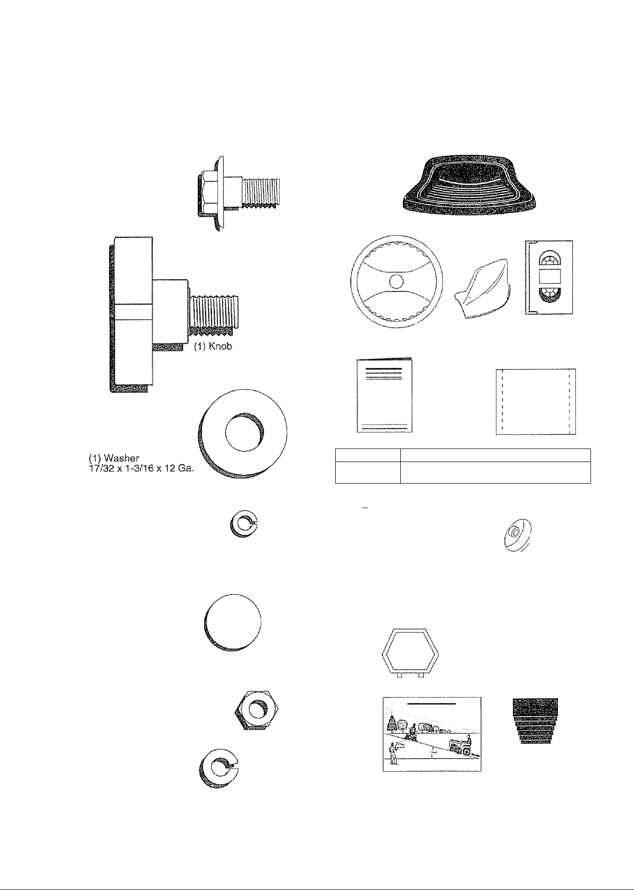
CONTENTS OF HARDWARE PACK
Parts Bag contents shown full size
(1) Shoulder Bolt
5/16-18
Parts packed separately in carton
Seat
Steering
Wheel
Mujcher
Plate
Cassette
Video
¡iliiilli
(2) Screws
#10x5/8
(2) Weld Nuts #10
(2) Washers 3/16 x 3/4 x 16 Gauge
{2) Lock
Washers
#10
o
Manual
Parts ba
B ai
(2) Shoulder lock Nuts
Bolts
g contents not shown full size
(2) Center-
XJ
(2) Latch Hook
Assemblies
Parts Bag
.
'/ Wheels
/ ^ \ (2) Washers 3/8
\ w j X 7/8 X 14 Gauge
Steering
Wheel
Insert
(2) Keys
(2) Gauge
,(2) Hex Bolts 1/4-20x3/4
) (2) Washers
/9/3
9/32 X 5/8
X 16 Ga.
(2) Hex Nuts 1/4-20
(2) Look
Washers 1/4
lj-srHia,
S
ivJL/ti OMuCfl
Steering
Sleeve
Page 7
ASSEMBLY
Your new tractor has been assembied at the factory with exception of those parts ieft unassembied for shipping purposes.
To ensure safe and proper operation of your tractor, ail parts and hardware you assembie must be tightened securely. Use
the correct tools as necessary to insure proper tightness.
TOOLS REQUIRED FOR ASSEMBLY
A socket wrench set will make assembly easier. Standard
wrench sizes are listed.
(2) 7/16" wrench Utility knife
(1) 3/4" socket w/drive ratchet Tire pressure gauge
Phillips screwdriver
When right and left hand is mentioned in this manual, it
means when you are in the operating position (seated
behind the steering wheel)
TO REMOVE TRACTOR FROM CARTON
UNPACK CARTON
* Remove all accessible loose parts and parts cartons
from carton (See page 6). ’
* Cut, from top to bottom, along lines on all four corners
of carton, and lay panels fiat,
« Remove mower and packing materials.
» Check for any additional loose parts or cartons and
remove.
BEFORE ROLLING TRACTOR OFF SKID
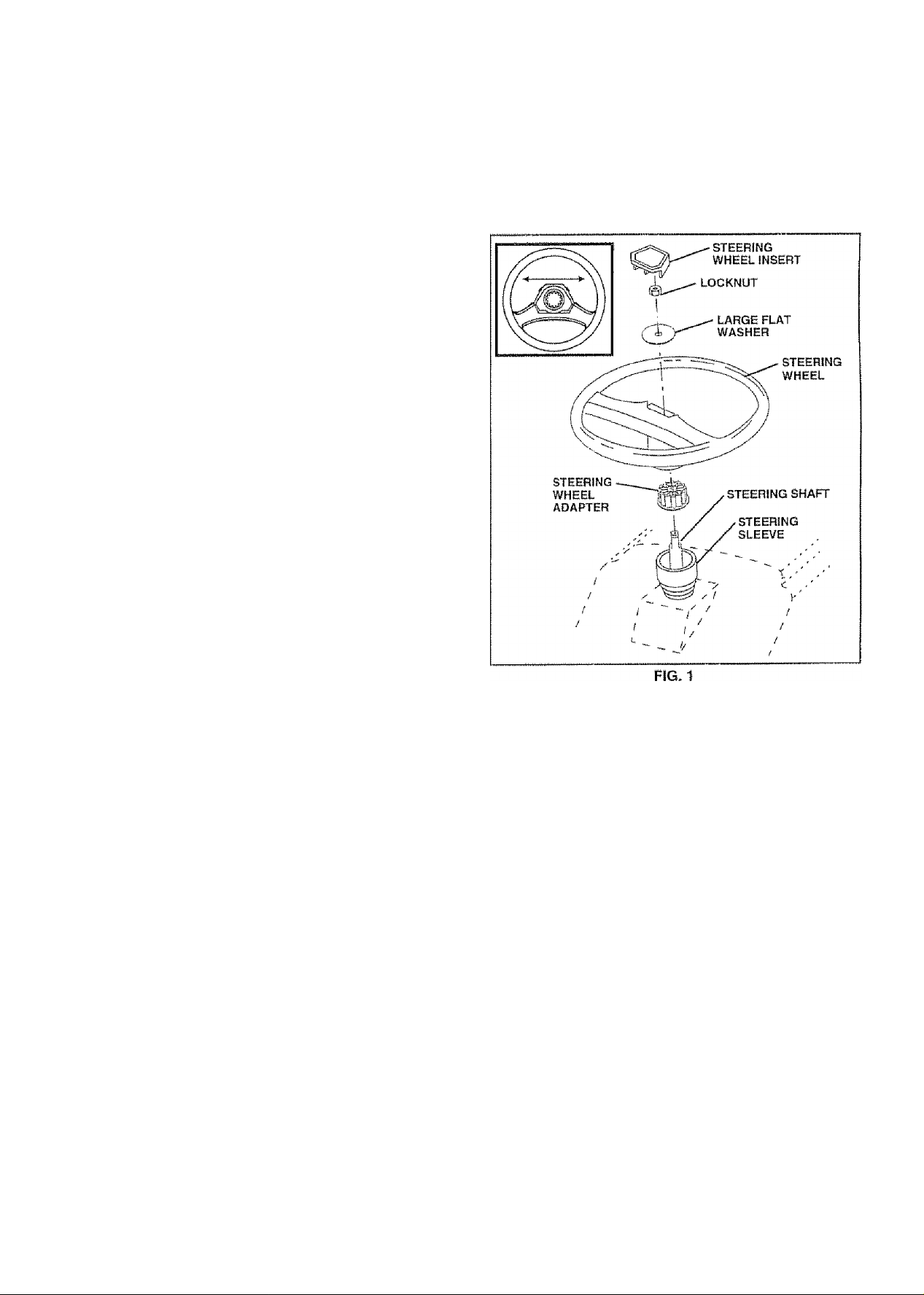
ATTACH STEERING WHEEL {See Fig. 1}
» Remove locknut and large flat washer from steering
shaft.
" Position front wheels of the tractor so they are pointing
straight forward,
“ Slide the steering sleeve over the steering shaft.
• Position steering wheel so cross bars are horizontal
(left to right) and slide onto adapter.
■* Secure steering wheel to steering shaft with locknut
and large flat washer previously removed. Tighten
securely,
" Snap steering wheel insert into center of steering
wheel.
• Remove protective materials from tractor hood and
grill.
IMPORTANT: CHECK FOR AND REMOVE ANY STAPLES
IN SKID THAT MAY PUNCTURETIRES WHERE TRACTOR
iS TO ROLL OFF SKID.
TO ROLL TRACTOR OFF SKID (See Opera
tion section for location and function of con
trols)
» Press lift lever plunger and raise attachment lift lever to
its highest position,
» Release parking brake by depressing clutch/brake
pedal.
« Place freewheel control in freewheeling position to
disengage transmission (See ‘TO TRANSPORT” in
the Operation section of this manual).
• Roll tractor backwards off skid.
Page 8

ASSEMBLY
HOW TO SET UP YOUR TRACTOR
CONNECT BATTERY (See Fig. 2)
»iHimaniiiunim'iiiiinn
CAUTION: Do not short battery termi
nals by allowing a wrench or any other
object to contact both terminals at the
same time. Before connecting batteryj
remove meta! bracelets, wristwatch
bands, rings, etc.
Positive terminal must be connected
first to prevent sparking from acciden
tal grounding.
• Lift hood to raised position.
<■ Open terminât access doors, remove terminal protec
tive caps and discard.
" If this battery is put into service after month and year
indicated on tabel (label located between terminals)
charge battery for minimum of one hour at 6-10 amps.
" First connect RED battery cable to positive (+) battery
terminal with hex bolt, flat washer, lock washer and hex
nut as shown, Tighten securely.
• Connect BLACK grounding cable to negative (-) bat
tery terminal with remaining hex bolt, flat washer, lock
washer and hex nut. Tighten securely.
» Close terminal access doors.
Use terminal access doors tor:
» Inspection for secure connections (to tighten hard
ware).
“ Inspection tor corrosion,
“ Testing battery.
" Jumping (if required),
® Periodic charging.
INSTALL SEAT (See Fig. 3)
Adjust seat before tightening adjustment knob« Remove cardboard packing on seat pan.
« Place seat on seat pan and assemble shoulder boit.
Tighten shoulder bolt securely.
• Assemble adjustment knob and flat washer loosely.
Do not tighten.
» Lower seat into operating position and sit on seat.
• Slide seat until a comfortable position is reached which
allows you to press clutch/brake pedal all the way
down.
« Get off seat without moving its adjusted position.
FIG. 3
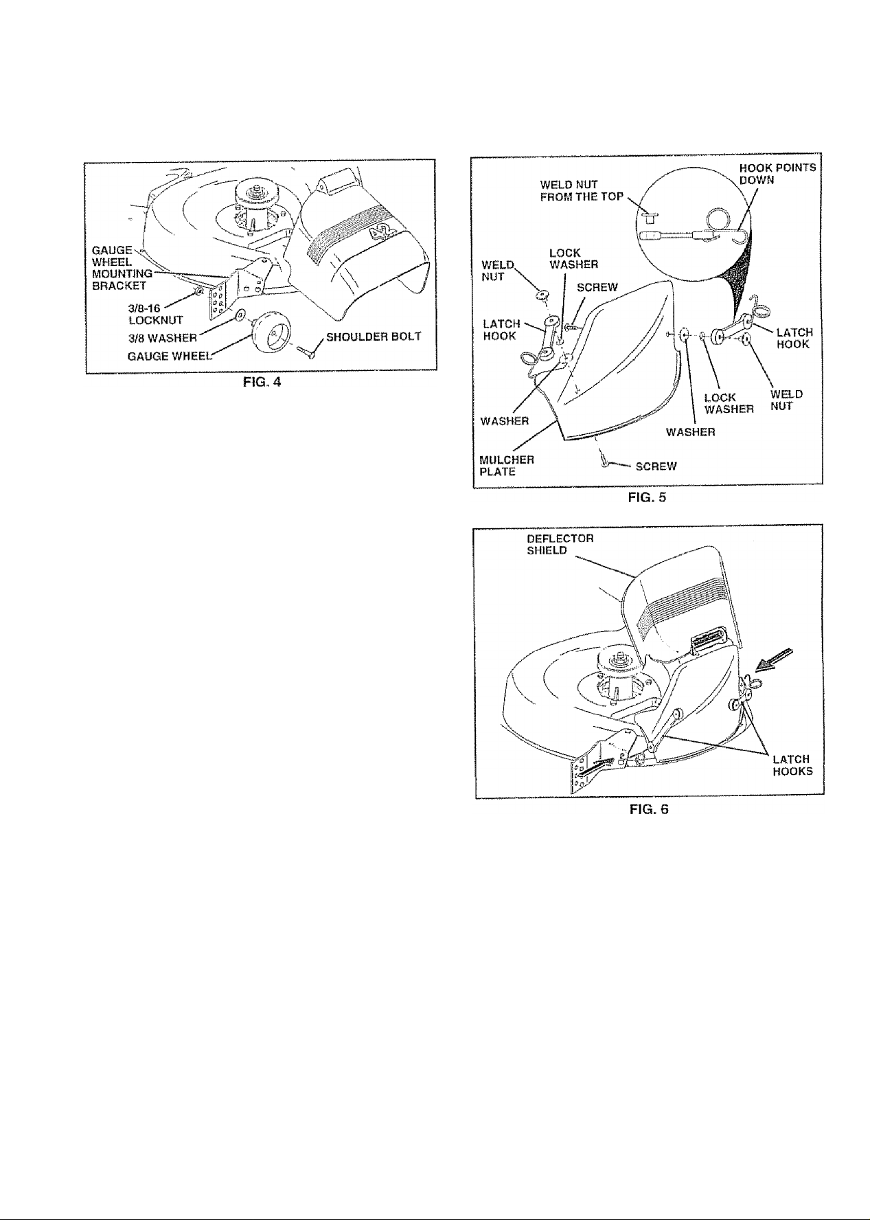
ASSEMBLE GAUGE WHEELS TO iVlOWER DECK (See Fig. 4)
The gauge wheels are designed to keep the mower deck in
proper position when operating mower. Be sure they are
properly adjusted to ensure optimum mower performance.
» Assemble gauge wheels with tractor on a fiat level
surface.
• Adjust mower to desired cutting height (See ‘TO AD
JUST MOWER CUTTING HEIGHT” in the Operation
section of this manual).
• With mower in desired height of cut position, gauge
wheels should be assembled so they are slightly off the
ground. Install gauge wheel in appropriate hole with
shoulder boit, 3)8 washer, and 3/8-16 locknut and
tighten securely..
0 Repeat for opposite side installing gauge wheel In
same adjustment hole.
8
Page 9
ASSEMBLY
INSTALL MULCHER PLATE (See Figs. 5 and
6)
• ¡nstaü two latch hooks to mulcher píate using screw,
washer, lock washer, and weld nut as shown.
NOTE: Pre-assembie weld nut to latch hook by inserting
weld nut froiTf the top with hook pointing down.
• Tighten hardware securely.
» Raise and hold deflector shield in upright position.
• Place front of mulcher plate over front of mower deck
opening and slide into place, as shown.
• Hook front latch Into hole on front of mower deck.
<* Hook rear latch into hole on back of mower deck.
CAUTION; Do not remove discharge
guard from mower. Raise and hold
A
TO CONVERT TO BAGGING OR
DISCHARGING
Simply remove mulcher plate and store in a safe place.
Your mower is now ready for discharging or installation of
optional grass catcher accessory.
NOTE: It is not necessary to change blades. The mulcher
blades are designed for discharging and bagging also.
guard when attaching mulcher plate
and allow It to rest on plate while in
operation.
Page 10

ASSEMBLY
CHECK TÍRE PRESSURE
The tires on your tractor were overinfiated at the factory for
shipping purposes. Correct tire pressure is important tor
best cutting performance.
« Reduce tire pressure to PS! shown in “PRODUCT
SPECIFICATIONS" on page 3 of this manual.
CHECK DECK LEVELNESS
For best cutting results, mower housing should be properly
leveled. See ‘TO LEVEL MOWER HOUSING” in the
Service and Adjustments section of this manual.
CHECK FOR PROPER POSITION OF ALL BELTS
See the figures that are shown for replacing motion and
mower blade drive belts in the Service and Adjustments
section of this manual. Verify that the belts are routed
correctly.
CHECK BRAKE SYSTEM
After you learn how to operate your tractor, check to see
that the brake is properly adjusted. See “TO ADJUST
BRAKE” in the Service and Adjustments section of this
manual.
/CHECKLIST
BEFORE YOU OPERATE AND ENJOY YOUR NEW
TRACTOR, WE WISH TO ASSURE THAT YOU RECEIVE
THE BEST PERFORMANCE A ND SA TISFA C TION FROM
THIS QUALITY PRODUCT
PLEASE REVIEW THE FOLLOWING CHECKLIST:
/ Alt assembly instructions have been completed,
/ No remaining loose parts in carton,
/ Battery Is properly prepared and charged. (Minimum
1 hour at 6 amps),
/ Seat is adjusted comfortably and tightened securely,
/ All tires are properly inflated. (For shipping purposes,
the tires were overinfiated at the factoiy)
/ Be sure mower deck is properly leveled side-to-side/
front-to-rear for best cutting results. (Tires must be
properly inflated for leveling),
/ Check mower and drive belts. Be sure they are routed
properly around pulleys and inside ail belt keepers,
/ Check wiring- See that all connections are stilS secure
and wires are properly clamped,
/ Before driving tractor, be sure freewheel control is in
drive position.
WHILE LEARNING HOWTO USE YOUR TRACTOR, PAY
EXTRA ATTENTION TO THE FOLLOWING IMPORTANT
ITEMS:
Engine oil is at proper level.
/
Fuel tank is filled with fresh, clean, regular unleaded
/
gasoline.
/
Become familiar with all controls - their (ocation and
function, operate them before you start the engine.
Be sure brake system is in safe operating condition.
/
It is important to purge the transmission before you
/
operate your new tractor for the first time. Follow
proper starting and transmission purging Instructions
(See "TO START ENGINE" and "PURGETRANSMISSION" in Operation section of this manual).
10
Page 11

OPERATION
These symbols may appear on your tractor or in literature supplied with the product. Learn and understand their meaning.
4
Q A
BATTERY
ENGINE ON ENGINE OFF OIL PRESSURE CLUTCH LIGHTS ON LIGHTS OFF
CAUTION OR
WARNING
STOP
REVERSE FORWARD FAST SLOW
I
■(•' 0= 0
4»
0 l\l â #
FUEL
CHOKE MOWER HEIGHT DIFFERENTIAL PARKING BRAKE
LOCK LOCKED
UNLOCKED
R N H L (®)|I
IL
REVERSE NEUTRAL HIGH LOW PARKING BRAKE
t
MOWER LIFT
DANGER, KEEP HANDS AND FEET AWAY
ATTACHMENT
CLUTCH ENGAGED
ATTACHMENT
CLUTCH DISENGAGED
■■■ ^
HYDROSTATIC FREE WHEEL
(Hydro Models only)
....
, //vSSmV
■;
11
Page 12
OPERATION
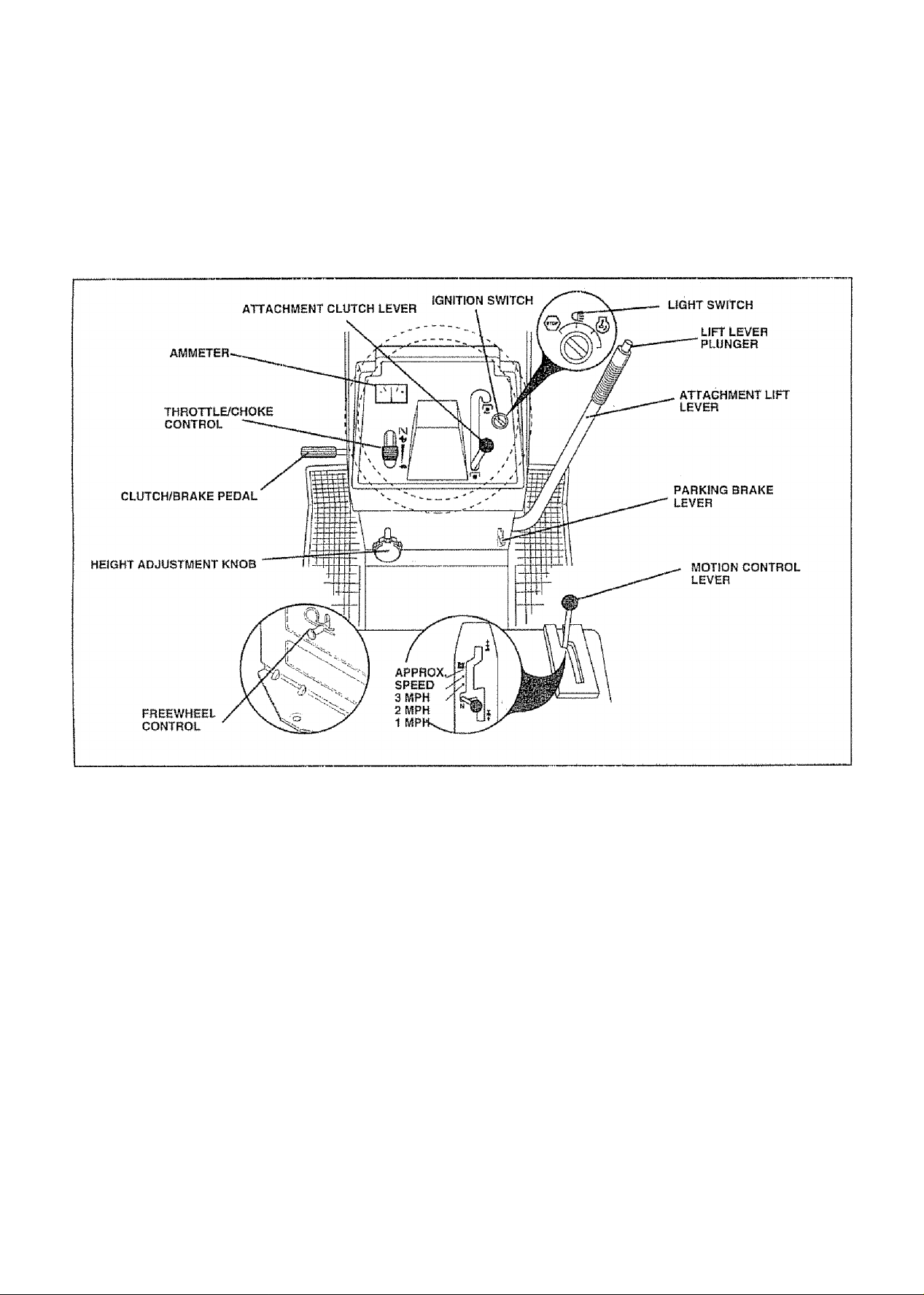
KNOW YOUR TRACTOR
READ THIS OWNER'S MANUAL AND SAFETY RULES BEFORE OPERATING YOUR TRACTOR
Compare the ilSustrattons with yourtractorlofamiiiarize yourself with the locations of various controls and adjustments. Save
this manual for future reference.
Our tractors conform to the safety standards of the American National Standards Institute,
ATTACHMENT CLUTCH LEV ER; Used to engage the
mower blades, or other attachments mounted to your
tractor,
LIGHT SWITCH: Turns the headlights on and off,
THROTTLE/CHOKE CONTROL: Used for starting and
controlling engine speed.
CLUTCH/BRAKE PEDAL: Used for declutching and brak
ing the tractor and starting the engine.
PARKING BRAKE LEVER: Locks clutch/brake pedal into
the brake position.
AMMETER - indicates charging (+) or discharging (-) of
battery.
FIG. 7
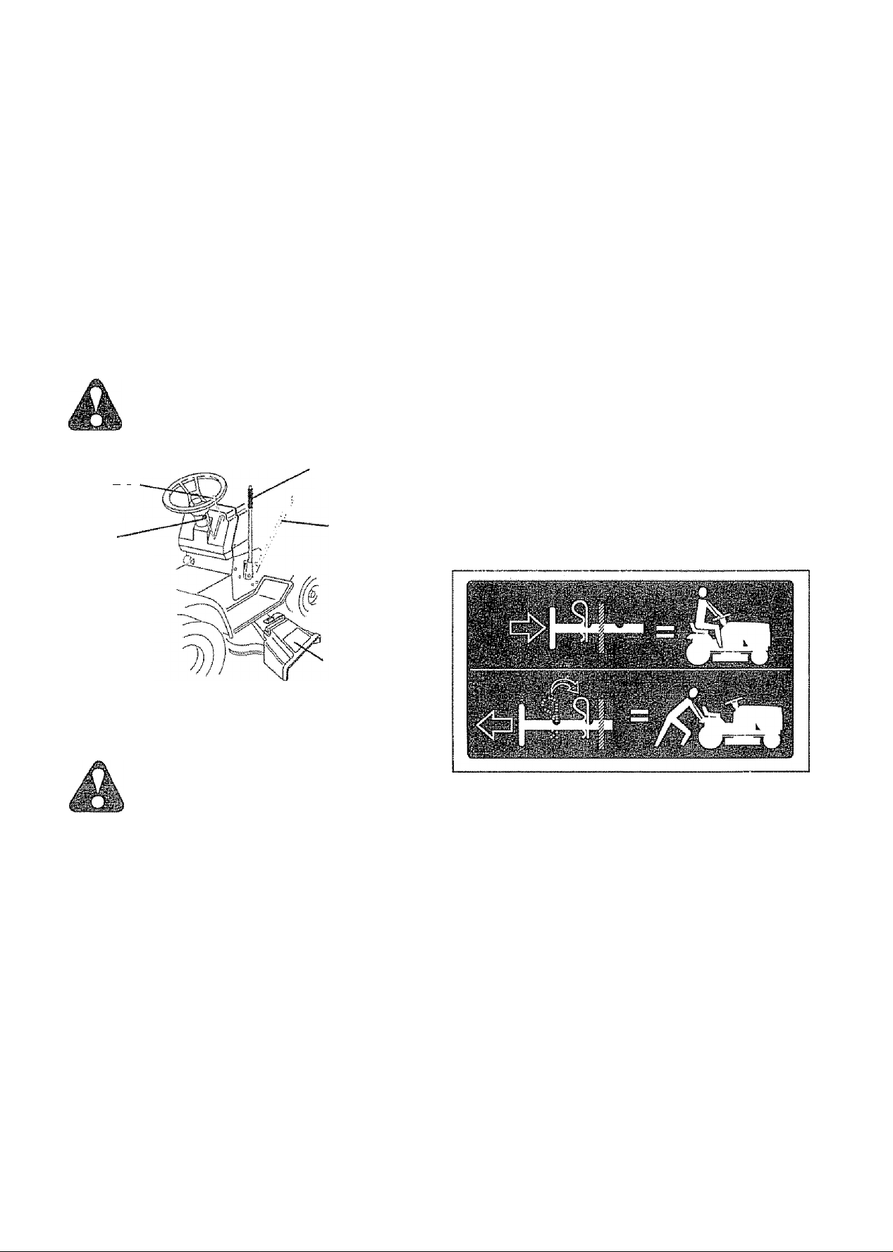
HEIGHT ADJUSTMENT KNOB: Used to reiease attach
ment lift lever when changing its position,
MOTION CONTROL LEVER: Selects the speed and
direction of tractor, ‘
LIFT LEVER PLUNGER; Used to release attachment lift
¡ever when changing its position.
ATTACHMENT LIFT LEVER; Used to raise and lower the
mower deck or other attachments mounted to your tractor.
IGNITION SWITCH: Used for starting and stopping the
engine,
FREEWHEEL CONTROL: Disengages transmission for
pushing or slowly towing the tractor with the engine off.
12
Page 13

OPERATION
The operation of any tractor can result in foreign objects thrown into the eyes, which can
result in severe eye damage. Always wear safety glasses or eye shields while operating your
tractor or performing any adjustments or repairs. We recommend a wide vision safety mask
over the spectacles or standard safety glasses.
HOW TO USE YOUR TRACTOR
TO SET PARKING BRAKE (See Fig. 8)
Your tractor is equipped with an operator presence sensing
switch. When engine is running, any attempt by the
operator to leave the seat without first setting the parking
brake will shut off the engine.,
• Depress ciutch/brake pedal into fuil “BRAKE” position
and hold,
” Place parking brake lever in "ENGAGED" position and
release pressure from ciutch/brake pedal. Pedal should
remain in "BRAKE” position. Make sure parking brake
will hold tractor secure.
ATTACHMENT CLUTCH LEVER
(GNITtON
KEY
THROTTLE/
CHOKE
CONTROL
LEVER
“BRAKE'
POSITION
CLUTCH/BRAKE
PEDAL "DRIVE"
POSITION
HEIGHT
ADJUSTMENT
KNOB
STOPPING (See Fig. 8)
MOWER BLADES " Move attachment clutch lever to “DISENGAGED" po
sition,
GROUND DRIVE -
■> Depress ciutch/brake pedal into full “BRAKE" position.
» Move motion control lever to neutral (N) position.
llylPORTANT: THE MOTION CONTROL LEVER DOES
NOT RETURN TO NEUTRAL (N) POSITION WHEN THE
CLUTCH/BRAKE PEDAL IS DEPRESSED
ENGINE"
“ Move throttie control to slow position.
NOTE; Failure to move throttie control to slow position and
allowing engine to idle before stopping may cause engine
to "bacWire",
"ENGAGED” POSITION
ATTACHMENT
CLUTCH LEVER
“DISENGAGED"
POSITION
PARKING BRAKE
"ENGAGED” POSITION
MOTION CONTROL
LEVER
PARKING BRAKE
"DISENGAGED" POSITION
FIG. 8
• Turn ignition key to “OFF" position and remove key.
Always remove key when leaving tractor to prevent
unauthorized use,.
• Never use choke to stop engine,
NOTE; Under certain conditions when tractor Is standing
idle with the engine running, hot engine exhaust gases may
cause "browning" of grass. To eliminate this possibiSity,
always stop engine when stopping tractor on grass areas.
CAUTION: Always stop tractor com
pletely, as described above, before leav
ing the operator's position; to empty
grass catcher, etc.
TO USE THROTTLE CONTROL (See Fig. 8)
Alv^ays operate engine at full throttle
» Operating engine at less than full throttle reduces the
battery charging rate. .
• Fuil throttle offers the best mower performance,
TO MOVE FORWARD AND BACKWARD (See Fig. 8)
The direction and speed of movement is controlled by the
motion control lever,
» Start tractor with motion control lever in neutral (N)
position.
• Release parking brake and ciutch/brake pedal.
• Slowly move motion control lever to desired position,
TO ADJUST MOWER CUTTING HEIGHT
(See Fig. 8)
The cutting height is controlled by turning the height adjust
ment knob in desired direction.
“ Turn knob clockwise ) to raise cutting height.
“ Turn knob counterclockwise {>^) to lower cutting
height.
The cutting height range is approximately 1 -1/2" to 4", The
heights are measured from the ground to the blade tip with
the engine not running. These heights are approximate
and may vary depending upon soil conditions, height of
grass and types of grass being mowed.
» The average lawn should be cut to approximately 2-1/2
inches during the cool season and to over 3 inches
during hot months. For healthier and better looking
lawns, mow often and after moderate growth,
» For best cutting performance, grass over 6 inches in
height should be mowed twice. Make the first cut
relatively high; the second to desired height.
13
Page 14
OPERATION
TO OPERATE MOWER (See Fig. 9)
Yourtractor is equipped with an operator presence sensing
switch. Any attempt by the operator to ieave the seat with
the engine running and the attachment clutch engaged will
shut off the engine,
» Select desired height of cut.
» Lower mower with attachment lift control,
» Start mower blades by engaging attachment clutch
control.
« TO STOP MOWER BLADES - disengage attachment
dutch control.
CAUTIOfJ: Do not operate the mower
without either the entire grass catcher,
on mowers so equipped, or the dis
charge guard In place.
ATTACHWIENT
CLUTCH LEVER
f II full lilir
POSITION
ATTACHI«ENT
CLUTCH LEVER
“OrSENGAOED”
POSITION
ATTACHMENT
LIFT LEVER
HIGH POSITION
LOW
POSITION
IMPORTANT: THE MOTION CONTROL LEVER DOES
NOT RETURN TO NEUTRAL (N) POSITION WHEN THE
CLUTCH/BRAKE PEDAL IS DEPRESSED,
« To restart movement, slowly release parking brake and
clutch/brake pedal.
• Slowly move motion control lever to slowest setting.
» Make all turns slowly.
TO TRANSPORT (See Figs. 7 and 10)
When pushing or towing your tractor, be sure to disengage
transmission by placing freewheel control in freewheeling
position. Free wheel control is located at the rear drawbar
of tractor,
« Raise attachment lift to highest position with attach
ment lift control.
« Puil freewheel control knob out and hold in position by
inserting retainer spring into forward hole of control rod.
• Do not push or tow tractor at more than two (2) MPH.
0 To reengage transmission, reverse above procedure.
NOTE: To protect hood from damage when transporting
yourtractor an a truck or a trailer, be sure hood is dosed and
secured to tractor. Use an appropriate means of tying hood
to tractor {rope, cord, etc.}.
DISCHARGE
GUARD
FIG. 9
TO OPERATE ON HILLS
CAUTION: Do not drive up or down
hills with slopes greater than 15° and
do not drive across any slope.
Choose the slowest speed before starting up or down
hills.
Avoid stopping or changing speed on hills.
if slowing !s necessary, move throttle control lever to
slower position.
If stopping is absolutely necessary, push cfutch/brake
pedal quickly to brake position and engage parking
brake.
Move motion control lever to neutral (N) position.
FIG. 10
BEFORE STARTING THE ENGINE
CHECK ENGINE OIL LEVEL (See Fig. 17)
• The engine in yourtractor has been shipped, from the
factory, already filled with summer weight oil.
» Check engine oil with tractor on level ground.
• Unthread and remove oil fill cap/dipstick; wipe oil off.
Reinsert the dipstick into the tube and rest oil fill cap on
the tube. Do not thread the cap onto the tube. Remove
and read oiSievei, If necessary, add oil until “FULL"
mark on dipstick is reached. Do not overfill.
For cold weather operation you should change oil for
easier starting {See “OIL VISCOSITY CHART' in the
Customer Responsibilities section of this manual).
® To change engine oil, see the Customer Responsibili
ties section in this manual.
14
Page 15

OPERATION
ADD GASOLINE
» Fill fue! tank. Use fresh, clean, regular unleaded
gasoline with a minimum of 87octane, (Use of leaded
gasoline will increase carbon and lead oxide deposits
and reduce valve lile). Do not mix oil with gasoline.
Purchase fuel In quantities that can be used within 30
days to assure fuel freshness.
IMPORTANT: WHEN OPERATING IN TEMPERATURES
BELOW 32”F(0”C), USE FRESH, CLEAN WINTER GRADE
GASOLINE TO HELP INSURE GOOD COLD WEATHER
STARTING.
WARNING; Experience indicates that alcohol blended
fuels (called gasohoi or using ethanol or methanol) can
attract moisture which leads to separation and formation of
acids during storage. Acidic gas can damage the fuel
system of an engine white in storage. To avoid engine
problems, the fuel system should be emptied before stor*
age of 30 days or longer. Drain the gas tank, start the
engine and let it run until the fuel lines and carburetor are
empty. Use fresh fuel next season. See Storage Instruc
tions for additional information. Never use .engine or
carburetor cleaner products in the fuel tank or permanent
damage may occur.
CAUTION: Fill to bottom of gas tank
filler neck. Do not overfill. Wipe off any
spilled oil or fuel. Do not store, spill or
use gasoline near an open flame.
COLD WEATHER STARTING ( 50« F and below)
» When engine starts, allow engine to run with the throttle
control in the choke position until the engine runs
roughly, then move throttle control to fast position. This
may require an engine warm-up period from several
seconds to several minutes, depending on the tem
perature.
HYDROSTATIC TRANSMISSION WARM UP
» Before driving the unit in cold weather, the transmis
sion should be warmed up as follows:
* Be sure the tractor is on level ground.
• Piace the motion control lever in neutral.
Release the parking brake and let the clutch/brake
slowly return to operating position.
» Allow one minute for transmission to warm up.
This can be done during the engine warm up
period,
« The attachments can also be used during the engine
warm-up period afterthe transmission has been warmed
up.
NOTE; If at a high altitude {above 3000 feet) or in cold
temperatures (below 32 F) the carburetor fuel mixture may
need to be adjusted for best engine performance. See "TO
ADJUST CARBURETOR" In the Service and Adjustments
section of this manual.
PURGE TRANSMISSION
TO START ENGINE (See Fig. 8)
When starting the engine for the first time or if the engine
has run out of fuel, it will take extra cranking time to move
fuel from the tank to the engine.
" Be sure freewheel control is in the transmission en
gaged position.
■> Sit on seat in operating position, depress clutch/brake
pedal and set parking brake,
» Place motion control lever in neutral (N) position.
■ Move attachment clutch to “DISENGAGED” position.
• Move throttle control to choke position
Note: Before starting, read the warm and cold starting
procedures below.
« Insert key into ignition and turn key clockwise to "START'
position and release key as soon as engine starts. Do
not run starter continuously for more than fifteen sec
onds per minuie. If the engine does not start after
several attempts, move throttle control to fast position,
wait afew minutes and try again. If engine still does not
start, move the throttle control back to the choke
position and retry.
WARM WEATHER STARTING (50° F and above)
» When engine starts, move the throttle control to the fast
position,
* The attachments and ground drive can now be used. If
the engine does not accept the load, restart the engine
and allow it to warm up for one minute using the choke
as described above.
CAUTION: Never engage or disengage
freewheel lever while the engine is run
ning.
To ensure proper operation and performance, it is recom
mended that the transmission be purged before operating
tractor for the first time. This procedure will remove any
trapped air inside the transmission which may have devel
oped during shipping of your tractor
IMPORTANT: SHOULD YOURTRANSMISSION REQUIRE
REMOVAL FOR SERVICE OR REPLACEMENT, IT
SHOULD BE PURGED AFTER REINSTALLATION
BEFORE OPERATING THE TRACTOR.
» Place tractor safely on level surface with engine off and
parking brake set..
» Disengage transmission by placing freewheel control
in freewheeling position (See “TO TRANSPORT" in
this section of manual).
■> Sitting in the tractorseat, start engine. Afterthe engine
is running, move throttle control to slow position. With
motion control lever in neutral (N) position, slowly
disengage clutch/brake pedal.
■> Move motion control lever to full forward position and
hold for five (5) seconds. Move lever to full reverse
position and hold for five (5) seconds. Repeat this
procedure three (3) times.
NOTE: During this procedure there will be no movement of
drive wheels. The air Is being removed from hydraulic drive
system.
15
Page 16
OPERATION
0 yove motion control leverto neutral (N) position.. Shut
off engine and set parking brake„
” Engage transmission by placing freewheel control in
driving position (See 'TO TRANSPORT” in this section
of manual).
« Sitting in the tractor seat, start engine. Afterthe engine
is running, move throttle control to half (1/2) speed..
With motion control lever in neutral (N) position, slowly
disengage cfutch/brake pedal.
» Slowly move motion control lever forward, after the
tractor moves approximately live (5) feet, slowly move
motion control lever to reverse position. After the
tractor moves approximately five (5) feet return the
motion control (ever to the neutral (N) position. Repeat
this procedure with the motion control lever three (3)
times.
® Your tractor is now purged and now ready for normal
operation.,
MOWING TIPS
® Tire chains cannot be used when the mower housing
is attached to tractor.
» Mower should be properly leveled for best mowing
performance. See ‘TO LEVEL MOWER HOUSING” in
the Service and Adjustments section of this manual.
“ The left hand side of mower should be used for trim
ming.
■> Drive so that clippings are discharged onto the area
that has been cut. Have the cut area to the right of the
machine. This will result in a more even distribution of
clippings and more uniform cutting.
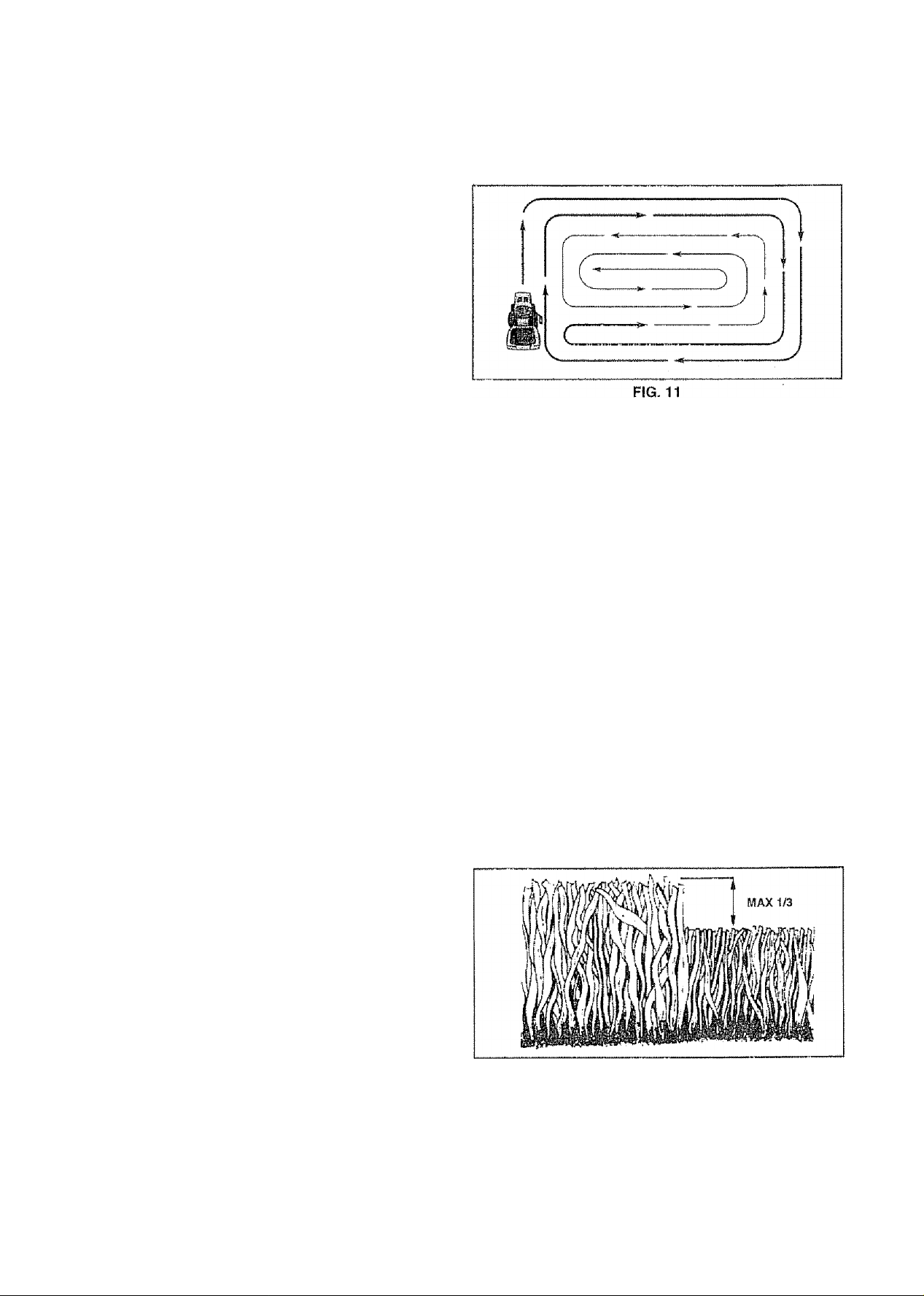
* When mowing large areas, start by turning to the right
so that clippings will discharge away from shrubs,
fences, driveways, etc. After one or two rounds, mow
in the opposite direction making left hand turns until
finished (See Fig. 11).
« If grass is extremely tali, it should be mowed twice to
reduce load and possible fire hazard from dried clip
pings. Make first cut relatively high; the second to the
desired height.
® Do not mow grass when it is wet. Wet grass will plug
mower and leave undesirable clumps. Allow grass to
dry before mowing,
« Always operate engine at full throttle when mowing to
assure better mowing performance and proper dis
charge of material. Regulate ground speed by select
ing a low enough gear to give the mower cutting
performance as well as the quality of cut desired.
" When operating attachments, select a ground speed
that will suit the terrain and give best performance of
the attachment being used
MULCHING MOWING TIPS
fMPORTANT: FOR BEST PERFORMANCE, KEEP
MOWER HOUSING FREE OF BUfLT-UP GRASS AND
TRASH, CLEAN AFTER EACH USE,
» The special mulching blade will recut the grass clip
pings many times and reduce them in size so that as
they fail onto the lawn they wiil disperse into the grass
and not be noticed. Also, the mulched grass will biode
grade quickly to provide nutrients for the lawn. Always
mulch with your highest engine (blade) speed as this
will provide the best recuttlng action of the blades.
” Avoid cutting your lawn when it is wet. Wet grass tends
to form clumps and interferes with the mulching action.
The best time to mow your lawn is the early afternoon.
At this time the grass has dried and the newly cut area
will not be exposed to the direct sun,
® For best results, adjustthemowercuttlngheightsothat
the mower cuts off only the top one-third of the grass
blades (See Fig. 12). For extremely heavy mulching,
reduce your width of cut on each pass and mow slowly.
' Certain types of grass and grass conditions may re
quire that an area be mulched a second time to
completely hide the clippings. When doing a second
cut, mow across or perpendicular to the first cut path.
» Change your cutting pattern from week to week. Mow
north to south one week then change to east to west the
next week. This wiil help prevent matting and graining
of the lawn.
16
FIG, 12
Page 17
CUSTOMER RESPONSIBILITIES
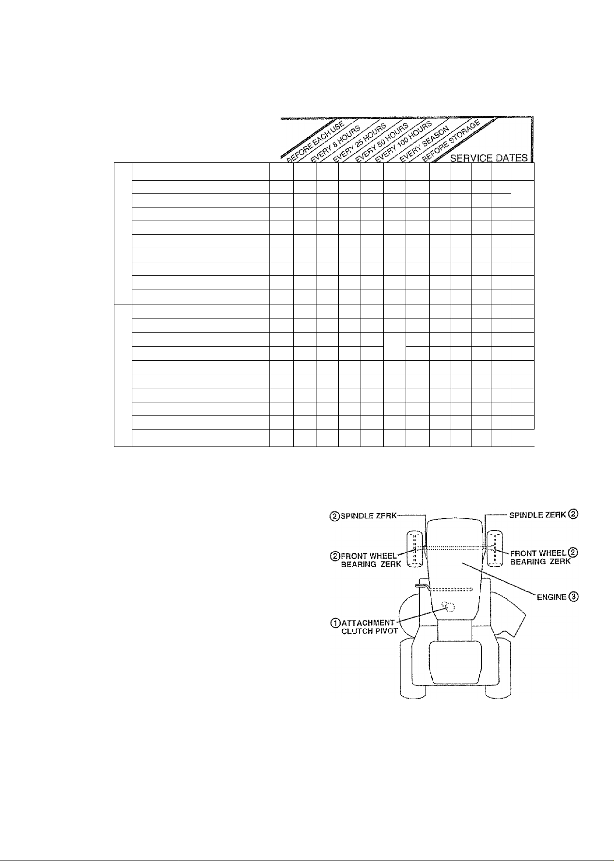
MAINTENANCE SCHEDULE
FILL IN DATES
AS YOU COMPLETE
REGULAR SERVICE
Check Brake Operation
Check Tire Pressure
Check for Loose Fasteners
T
R
Sharpen/Rapiacs Mower Blades
A
Lubrication Chart ^
w
Check Battery Level/Recharge
T
Clean Battery and Terminals
0
R
Check Transaxle Cooilrtg
Adjust Blade Belt(s) Tension
Adjust Motion Drive Beltjs) Tension
Check Engine Oil Level
Change Engine Oil
Clean Air Filter
E
Clean Air Screen
N
Inspect Muffler/Spark Arrester
G
I
Replace Oil Fitter (If equipped)
N
Clean Engine Cooling Fins
Replace Spark Plug
Replace Air Filter Paper Cartridge
Replace Fuel Filter
1 - Change more oiton when operaiing under a heavy Soad or)« high ambient temperalijres
2 - Servlca more often whan operaiing in dirty or dusty conditions
3 - II equipped with oii filler, change oi! every 50 hours.
4 - Raplace blades more ofiet! when mowing in sandy soil
✓
✓
1/
✓ 4
1/
✓ б
1/
6/
✓
^2.3
г
2
1^7
б/=
í/s
ft/
|/
ft/
6/
61^, г
✓
|/г
в/
S - If equipped with adjustable system
0 - Not required if equipped with maimenancB-lree balfery
7 - Tighten front axle pivot bolt to 35 it -fbs maximum
Do not ovsrsighteri
1
GENERAL RECOMMENDATIONS
The warranty on this tractor does not cover items that have
been subjected to operator abuse or negligence. To
receive full value from the warranty, operatormusi maintain
tractor as instructed in this manual.
Some adjustments will need to be made periodically to
property maintain your tractor.
A!! adjustments in the Service and Adjustments section of
this manua! should be checked at least once each season.
« Once a year you should replace the spark piug, clean
or replace air filter, and check blades and belts for
wear. A new spark plug and clean air filter assure
proper air-fuel mixture and help your engine run better
and last longer.
BEFORE EACH USE
» Check engine oil level.
» Check brake operation.
» Check tire pressure.
• Check for ioose fasteners.
LUBRICATION CHART
фзАЕ 30 МОТОВ Ott
(Doeneral purpose grease
ФREFER TO CUSTOMER RESPONSIBIUTIES “ENGtNE" SECTiON
IMPORTANT; DO NOT OIL OR GREASE THE PiVOT POINTS,
WHICH HAVE SPECIAL NYLON BEARiNQS VISCOUS LUBRI
CANTS WILL ATTRACT DUST AND DIRT THAT WILL SHORTEN
THE LIFE OF THE SELF-LUBRiCATING BEARiNQS. IF YOU
FEEL THEY MUST BE LUBRICATED, USE ONLY A DRY, POW
DERED QRAPHire TYPE LUBRICANT SPARINGLY,
17
Page 18
CUSTOMER RESPONSIBILITIES
TRACTOR
Always observe safety rules when performing any mainte
nance.
BRAKE OPERATION
if tractor requires more than six (6) feet stopping distance
at high speed in highest gear, then brake must be adjusted.
(See 'TO ADJUST BRAKE” in the Service and Adjust
ments section of this manual).
TIRES
® Maintain proper air pressure in all tires (See "PROD
UCT SPECfPiCATIONS” on page 3 of this manual).
» Keep tires free of gasoline, oii, or insect control chemi
cals which can harm rubber.
» Avoid stumps, stones, deep ruts, sharp objects and
other hazards that may cause tire damage,
NOTE; To seal tire punctures and prevent flat tires due to
slow leaks, tire sealant may be purchased from your local
parts dealer. Tire sealant also prevents tire dry rot and
corrosion,
BLADE CARE
For best results mower blades must be kept sharp. Re
place bent or damaged blades,
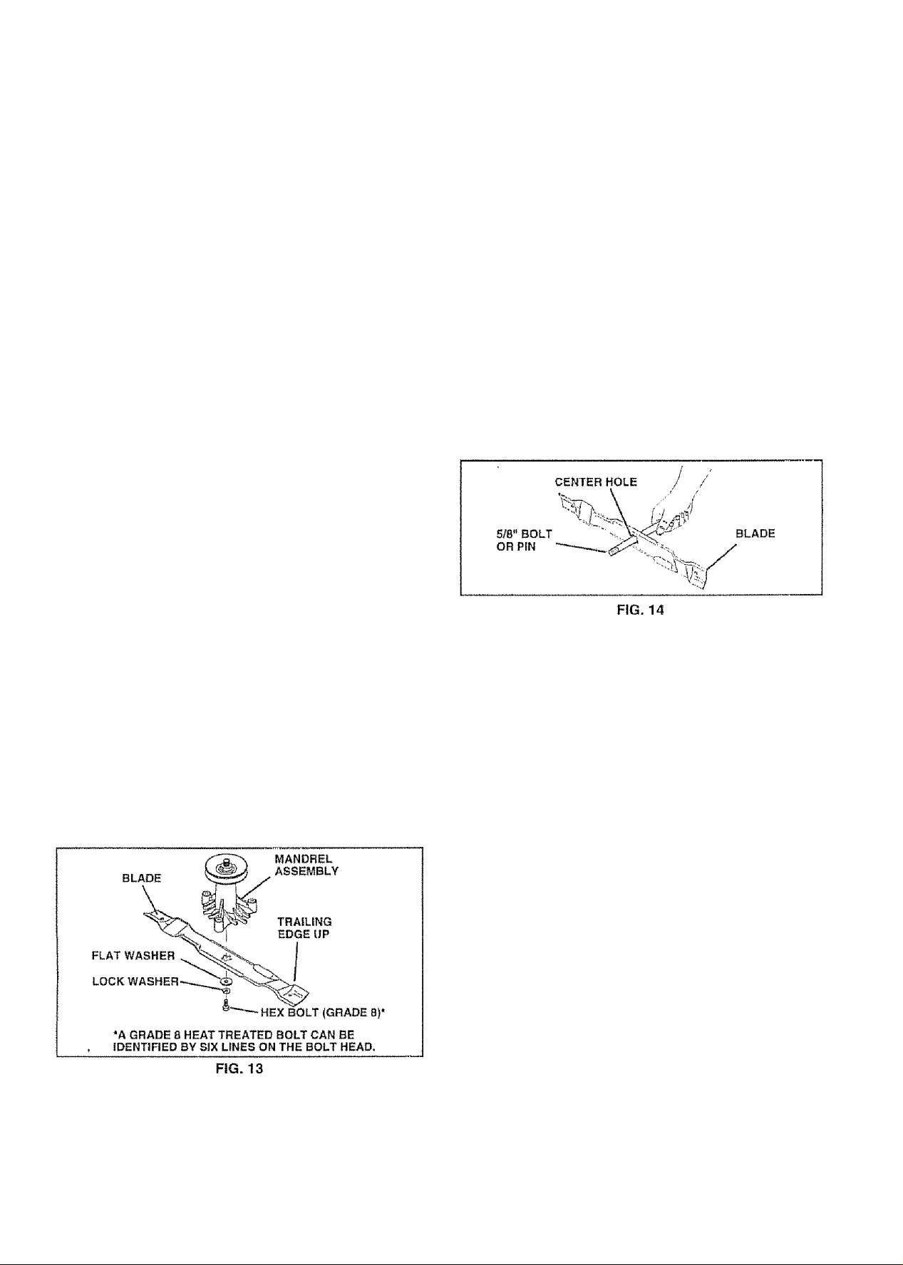
TO SHARPEN BLADE (See Fig. 14)
Care should be taken to keep the blade balanced- An
unbalanced blade will cause excessive vibration and even
tual damage to mower and engine.
“ The blade can be sharpened with a file or on a grinding
wheel. Do not attempt to sharpen while on the mower.
• To check blade balance, you will need a 5/8" diameter
steel bolt, pin, or a cone balancer (When using a cone
balancer, follow the Instructions supplied with bal
ancer).
» Slide blade on to an unthreaded portion of the steel bolt
or pin and hold the bolt or pin parallel with the ground.
If blade is balanced, it should remain in a horizontal
position. If either end of the blade moves downward,
sharpen the heavy end until the blade is balanced.
NOTE: Do not use a nail for balancing blade. The lobes of
the center hole may appear to be centered, but are not.
BLADE REMOVAL (See Fig. 13)
• Raise mower to highest position to allow access to
blades,
• Remove hex bolt, lock washer and flat washer securing
blade
» Install new or resharpened blade with trailing edge up
towards deck as shown.
" Reassemble hex bolt, iock washer and fiat washer in
exact order as shown.
“ Tighten bolt securely (30-35 Ft, Lbs, torque).
IMPORTANT: BLADE BOLT IS GRADE 8 HEAT TREATED.
NOTE: We do not recommend sharpening blade-but if you
do, be sure the blade is baianced.
BATTERY
Your tractor has a battery charging system which is suffi
cient for normal use. However, periodic charging of the
battery with an automotive charger will extend its life.
» Keep battery and terminals clean,
o Keep battery bolts tight.
• Keep small vent holes open.
» Recharge at 6-10 amperes for 1 hour.
TO CLEAN BATTERY AND TERMINALS
Corrosion and dirt on the battery and terminals can cause
the battery to “leak” power.
" Remove terminal guard.
» Disconnect BLACK battery cable first then RED bat
tery cable and remove battery from tractor.
' Rinse the battery with plain water and dry.
» Clean terminals and battery cable ends with wire brush
until bright
» Coat terminals with grease or petroleum jelly,
• Reinstall battery (See "CONNECT BATTERY" in the
Assembly section of this manual).
18
Page 19

CUSTOMER RESPONSIBILITIES
TRANSAXLE COOLING
The fan and cooiing fins of transmission should be kept
clean to assure proper cooling.
Do not attempt to clean fan or transmission while engine is
running or while the transmission is hot.
® Inspect cooling fan to be sure fan blades are intact and
clean.
* Inspect cooling fins for dirt, grass clippings and other
materials. To prevent damage to seals, do not use
compressed air or high pressure sprayer to clean
cooling fins,
TRANSAXLE PUMP FLUID
The transaxie was sealed at the factory and fluid mainte
nance is not required for the life of the transaxle. Should the
transaxle ever leak or require servicing, contact your near
est authorized service center/department.
V-BELTS
Check V-be!ts for deterioration and wear after 100 hours of
operation and replace if necessary. The belts are not
adjustable. Replace belts if they begin to slip from wear,
ENGINE
LUBRICATION
Only use high quality detergent oil rated with API service
classification SF, SG or SH. Select the oil's SAE viscosity
grade according to your expected operating temperature.
SAE VISCOSITY GRADES
TO CHANGE ENGINE OIL (See Figs. 15 and 16)
Determine temperature range expected before oil change.
All oil must meet API sen^'ice classification SF, SG or SH.
Be sure tractor is on level surface.
Oil will drain more freely when warm.
Catch oil in a suitable container.
Remove oil fill cap/dipstick. Be careful not to allow dirt
to enter the engine when changing oil.
Remove drain plug.
After oil has drained completely, replace oil drain plug
and tighten securely.
Refill engine with oil through oil fill dipstick tube. Pour
slowly. Do not overfill. For approximate capacity see
“PRODUCT SPECIFICATIONS” on page 3 of this
manual.
Use gauge on oil fill cap/dipstick for checking level.
Insert dipstick into the tube and rest the oi! fill cap on the
tube. Do not thread the cap onto the tube when taking
reading. Keep oil at “FULL” line on dipstick. Tighten
cap onto the tube securely when finished.
AIR CLEANER
COVER
FOAM
PRE-CLEANER
AIR CLEANER
PAPER
CARTRIDGE
COVER KNOB
WfNQ NUT
RUBBER
GROMMET
AIR CLEANER
BASE
OIL FILL
CAP/OtPSTICK
50* 32" 40" 60" eo" 100*
°C -30' -SO' -10*
TEMPERATURE RANGE ANTICIPATED BEFORE NEXT OIL CHANGE
0" 10“ 20“ 30“ 40“
FIG. 15
NOTE: Although multi-viscosity oils {5W30, 10W30 etc.)
improve starting in cold weather, these multi-viscosity oils
will result in increased oil consumption when used above
32“F. Check your engine oil level more frequently to avoid
possible engine damage from running low on oil.
Change the oil after every 50 hours of operation or at least
once a year if the tractor is not used for 50 hours in one year.
Check the crankcase oil level before starling the engine and
after each eight (8) hours of operation.. Tighten oil fill cap/
dipstick securely each time you check the oil level.
OIL DRAIN
PLUG'
AtR SCREEN
FIG. 16
CLEAN AIR SCREEN (See Fig. 16)
Air screen must be kept free of dirt and chaff to prevent
engine damage from overheating. Clean with a wire brush
or compressed air to remove dirt and stubborn dried gum
fibers
19
Page 20

CUSTOMER RESPONSIBJLITIES
AIR FILTER (See Fig. 16)
Your engine will not run properly using a dirty air filterClean the foam pre-cleaner after every 25 hours of opera
tion or eveiy season, Service paper cartridge every 100
hours of operation or every season, whichever occurs first.
Service air cleaner more often under dusty conditions,
• Remove knob and cover.
® Remove wing nut and air cleaner from base.
TO SERVICE PRE-CLEANER
' Slide foam pre-cleaner off cartridge.
" Wash it in liquid detergent and water.
» Squeeze It dry in a clean cloth- Allow It to dry.
“ Saturate it in engine pii. Wrap it In dean, absorbent
cloth and squeeze to remove excess oil.
TO SERVICE CARTRIDGE
" Replace a dirty, bent, or damaged cartridge.
NOTE: Do not wash the paper cartridge or use pressurized
air, as this will damage the cartridge.,
® Reinstall the pre-cteaner (cleaned and oiled) over the
paper cartridge
® Reassemble air cleaner, wing nut, cover and tighten
knob securely,
CLEAN AIR INTAKE/COOLING AREAS
To Insure proper cooling, make sure the grass screen,
cooling fins, and other external surfaces of the engine are
kept clean at all times.
Every 100 hours of operation (more often under extremely
dusty, dirty conditions), remove the blower housing and
other cooling shrouds. Clean the cooling fins and external
surfaces as necessary,, Make sure the cooling shrouds are
reinstalled,
NOTE: Operating the engine with a blocked grass screen,
dirty or plugged cooling fins, and/or cooling shrouds re
moved will cause engine damage due to overheating.
ENGINE OIL FILTER (SeeFtg. 17)
Replace the engine oil filter every season or every other oil
change if the tractor Is used more than 100 hours in one
year
‘ Drain oil from engine crankcase (See 'TO CHANGE
ENGINE OIL” in this section of this manual, through
step remove drain plug).
® Remove oil filter and wipe off filter adapter.
» Apply a thin coating of new engine oil to the rubber
gasket on replacement oil filter.
“ Install replacement oil filter on filter adapter. Turn oil
filter clockwise until rubber gasket contacts the filter
adapter, then tighten filter an additional 1/2 turn,
» Fill crankcase with new oil (See 'TO CHANGE EN
GINE OIL” in this section of this manual). For approxi
mate capacity see "PRODUCT SPECIFICATIONS” on
page 3 of this manual,
« Start the engine and check for oil leaks. Correct any
leaks before placing engine into full operation.
MUFFLER
Inspect and replace corroded muffler and spark arrester (if
equipped) as It could create a fire hazard and/or damage.
SPARK PLUGS
Replace spark plugs at the beginning of each mowing
season or after every 100 hours of use, whichever comes
first. Spark plug type and gap setting is shown in “PROD
UCT SPECIFICATIONS" on page 3 of this manual
IN-LINE FUEL FILTER (See Fig. 18)
The fuel filter should be replaced once each season, if fuel
filter becomes dogged, obstructing fuel flow to carburetor,
replacement is required.
» With engine cool, remove filter and plug fuel line
sections.
" Place new fuel filter in position in fuel line with arrow
pointing towards carburetor
® Be sure there are no fuel line leaks and clamps are
properly positioned.
® Immediately wipe up any spilled gasoline.
CLEANING
* Clean engine, battery, seat, finish, etc, of all foreign
matter.
“ Keep finished surfaces and wheels free of all gasoline,
oil, etc,
• Protect painted surfaces with automotive type wax.
We do not recommend using a garden hose to clean your
tractor unless the eiectrlca! system, muffler, air filter and
carburetor are covered to keep water out. Water in engine
can result in a shortened engine Hie.
20
Page 21

CAUTION; BEFORE PERFORMING ANY SERVICE OR ADJUSTMENTS;
® Depress clutch/brake pedal fully and set parking brake,
e Place motion control lever in neutral (N) position.
• Place attachment clutch in “DISENGAGED^* position.
A
• Turn ignition key "OFF” and remove key.
0 Make sure the blades and all moving parts have completely stopped.
« Disconnect spark plug wire from spark plug and place wire where it cannot come in contact with
SERVICE AND ADJUSTMENTS
plug.
___________________
_
TO REMOVE MOWER (See Fig. 19)
Mowerwil! beeasierto remove from the right side of tractor.
• Place attachment clutch in “DISENGAGED" position
Move attachment lift lever forward to lower mowerto Its
lowest position.
Roll belt off engine pulley.
Disconnect clutch rod from clutch lever by removing
retainer spring. ^
Disconnect anti^sway bar from chassis bracket by
removing retainer spring
Disconnect suspension arms from rear deck brackets
by removing retainer springs.
Disconnect front links from deck by removing retainer
springs,
Raise lift lever to raise suspension arms. Slide mower
out from under tractor,
IMPORTANT: IF AN ATTACHMENT OTHER THAN THE
MOWER DECK iS TO BE MOUNTED ON THE TRACTOR,
REMOVE THE FRONT LINKS
TO INSTALL MOWER (See Fig. 19)
» Raise attachment lift lever to its highest position.
» Slide mower undertractorvtfith discharge guard to right
side of tractor.
• Lower lift lever to its lowest position.
• Install mower in reverse order of removal instructions.
CLUTCH LEVER
RETAINER
SPRING
ENGINE
PULLEY
FRONT
LINK
FIG. 19
21
Page 22

SERVICE AND ADJUSTMENTS
TO LEVEL MOWER HOUSING
Adjust the mower while tractor is parked on level ground or
driveway. Make sure tires are properly inflated (See
“PRODUCT SPECIFICATIONS”on page 3of this manual).
If tires are over or underinfiated, you will not properly adjust
your mower.
SIDE-TO-SIDE ADJUSTMENT (See Figs. 20 and 21)
« Raise mower to its highest position.
- At the midpoint of both sides of mower, measure height
from bottom edge of mowsrto ground. Distance "A” on
both sides of mower should be the same or within 1/4"
of each other,
« If adjustment is necessary, make adjustment on one
side of mower only.
• To raise one side of mower, tighten lift link adjustment
nut on that side.
• To lower one side of mower, loosen lift link adjustment
nut on that side.
NOTE: Each full turn of adjustment nut wilt change mower
height about 1/8",
® Recheck measurements after adjusting.
FRONT-TO^BACK ADJUSTMENT (See Figs. 22 and 23)
iMPORTANT: DECK MUST BE LEVEL SlDE-TO-SIDE, IF
THE FOLLOWING FRONT-TO-BACK ADJUSTMENT iS
NECESSARY, BE SURE TO ADJUST BOTH FRONT LINKS
EQUALLY SO MOWER WILL STAY LEVEL SIDE-TO-
S!0£,
To obtain the best cutting results, the mower housing
should be adjusted so that the front is approximately 1 /8" to
1/2" lower than the rear when the mower is in its highest
position.
Check adjustment on right side of tractor, Measure dis
tance "D” directiy in front and behind the mandrel at bottom
edge of mower housing as shown.
" Before making any necessary adjustments, check that
both front links are equal in length, Both links should be
approximately 10-3/8".
• If links are not equal in length, adjust one iink to same
length as other link.
' To lower front of mower loosen nut "E“’ on both front
links an equal number of turns,.
• When distance “D" is 1/8" to 1/2" lower at front than
rear, tighten nuts "F" against trunnion on both front
links.
■> To raisefront of mower, loosen nut "F” from trunnion on
both front links. Tighten nut “E” on both front links an
equal number of turns.
» When distance "D" is 1/8“ to 1/2" lower at front than
rear, tighten nut “F” against trunnion on both front links.
» Recheck side-to-side adjustment
Page 23

SERVICE AND ADJUSTMENTS
TO REPLACE MOWER BLADE DRIVE BELT
(See Fig. 24)
The mower blade drive belt may be replaced without tools.
Park the tractor on level surface. Engage parking brake
BELT REMOVAL -
• Remove mower from tractor (See ‘TO REMOVE
MOWER" in this section of this manual).
• Work belt off both mandrel pulleys and idler pulleys.
« Pull belt away from mower.
BELT INSTALLATION -
• install new belt In reverse order of removal.
• Make sure belt is in all pulley grooves and Inside all belt
guides.
• install mower in reverse order of removal instructions.
TO ADJUST BRAKE (See Fig. 25)
Your tractor is equipped with an adjustable brake system
which is mounted on the right side of the transaxte.
if tractor requires more than six (6) feet stopping distance
at high speed in highest gear, then brake must be adjusted.
• Depress dutch/brake pedal and engage parking brake.
• Measure distance between brake operating arm and
nut "A" on brake rod.
« if distance is otherthan 1-3/4", loosen jam nut and turn
nut "A" until distance becomes 1-3/4". Retighten jam
nut against nut "A".
® Roadtesttractorforproperstopplngdistanceasstated
above. Readjust if necessary. If stopping distance Is
stilt greater than six (6) feet in highest gear, further
maintenance is necessary. Contact your nearest au
thorized service center..
WITH PAftKtNG BRAKE
________
"ENGAGED"
JAM
NUT
OPERATiNG
ARM
DO NOTTOUCHTHIS NUT. !F FURTHER BRAKE ADJUSTMENT IS
NECESSARY, CONTACT YOUR NEAREST AUTHORIZED SERVICE
CENTER/DEPARTMENT
FIG. 25
23
Page 24

SERVICE AiMD ADJUSTMENTS
TO REPLACE MOTION DRIVE BELT
(See Fig. 26)
Park the tractor on level surface. Engage parking brake.
For assistance, there is a belt installation guide decal on
bottom side of left footrest.
• Remove mower (See ‘TO REMOVE MOWER” in this
section of this manual.)
• Remove upper belt keeper,
» Remove belt from stationary Idler and clutching idler.
“ Puli belt slack toward rear of tractor. Carefully remove
belt upwards from transmission input pulley and over
cooling Ian blades.
• Pull belt toward front of tractor and remove downward
from around engine pulley.
« Install new belt by reversing above procedure.
IMPORTANT; MAKE SURE UPPER BELT KEEPER IS
POSiTSONED PROPERLY BETWEEN LOCATOR TAB,
TO ADJUST MOTION CONTROL LEVER
(See Fig. 27)
The motion control lever has been preset at the factory and
adjustment should not be necessary.
if for any reason the motion control lever wtl! not hold its
position while at a selected speed, it may be adjusted at the
friction pack located on the right side of transmission.
* Park tractor on level surface. Stop tractor by turning
ignition key to “OFF" position, and engage parking
brake-
» Adjust motion control lever by tightening adjustment
locknut one half (1/2) turn,
NOTE: If for any reason the effort to move the motion
control lever becomes too excessive, reverse the above
adjustment procedure by loosening locknut 1/4 to 1/2 turn.
Road test tractor after adjustment and repeat procedure if
necessary.
TRANSMISSION REMOVAUREPLACEMENT
Should your transmission require removal for service or
replacement, it should be purged after reinstallation and
before operating the tractor, See “PURGE TRANSMIS
SION" in Operation section of this manual.
24
Page 25

SERVICE AND ADJUSTMENTS
TO ADJUST STEERING WHEEL ALIGNMENT
II steering wheel crossbars are not horizontal (left to right)
when wheelsare positioned straightforward, remove steer'
ing wheel and reassemble per instructions in the Assembly
section of this manual.
FRONT WHEEL TOE-IN/CAMBER
The front wheel toe-in and camber are not adjustable on
your tractor. If damage has occurred to affect the front
wheel toe-in or camber, contact your nearest authorized
service center/department.
TO REMOVE WHEEL FOR REPAIRS
(See Fig. 28)
Block up axle securely..
Remove axle cover, retaining ring and washers to atiow
wheel removal (rear wheei contains a square key - Do
not lose).
Repair tire and reassemble.
On rear wheels only; align grooves in rear wheel hub
and axle. Insert square key.
Replace washers and snap retaining ring securely in
axle groove.
Replace axle cover.
NOTE: To seal tire punctures and prevent flat tires due to
slow leaks, tire sealant may be purchased from your local
parts dealer. Tire sealant also prevents tire dry rot and
corrosion.
WASHERS
RETAINING
RING\
AXLE COVER
SQUARE KEY (REAR
WHEEL ONLY)
FIG. 28
25
Page 26

SERVICE AND ADJUSTMENTS
TO START ENGINE WITH A WEAK BATTERY
(See Fig. 29)
A
if your battery is too weak to start the engine, it should be
recharged. If “jumper cables" are used for emergency
starting, follow this procedure;
IMPORTANT; YOUR TRACTOR IS EQUIPPED WITH A 12
VOLT NEGATIVE GROUNDED SYSTEM. THE OTHER
VEHICLE MUST ALSO BE A 12 VOLT NEGATIVE
GROUNDED SYSTEM. DO NOT USE YOUR TRACTOR
BATTERY TO START OTHER VEHICLES,
TO ATTACH JUMPER CABLES -
* Connect each end of the RED cable to the POSITIVE
(-f) terminal of each battery, taking care not to short
against chassis.
» Connect one end of the BLACK cable to the NEGA
TIVE {-) terminal of fully charged battery.
« Connect the other end of the BLACK cable to good
CHASSIS GROUND, away from fuel tank and battery.
TO REMOVE CABLES, REVERSE ORDER » BLACK cable first from chassis and then from the fully
charged battery.
» RED cable last from both batteries.
* *
CAUTION: l,ead-aciti batteries gener
ateexplosive gases. Keep sparks, flame
and smoking materials away from bat
teries. Always wear eye protection
when around batteries.
TO REPLACE HEADLIGHT BULB
» Raise hood.
» Pull bulb holder out of the hole in the backside of the
grill
“ Replace bulb In holder and push bulb holder securely
back into the hole in the backside of the grlli,.
» Close hood.
INTERLOCKS AND RELAYS
Loose or damaged wiring may cause your tractor to run
pooiiy, stop running, or prevent it from starting
“ Check wiring. See electrical wiring diagram in the
Repair Parts section of this manual,
TO REPLACE FUSE
Replace with 30 amp automotive-type plug-in fuse. The
fuse holder is located behind the dash,
TO REMOVE HOOD AND GRILL ASSEMBLY
(See Fig. 30)
» Raise hood,
• Unsnap headlight wire connector.
» Stand in front o! tractor. Grasp hood alsides,tilttoward
engine and lift off of tractor,
» To replace, reverse above procedures.
"POStTiVE" (+) "NEGATIVE" {-)
FIG. 29
26
Page 27

SERVICE AND ADJUSTMENTS
ENGINE
TO ADJUST THROTTLE CONTROL CABLE
(See Fig. 31)
The throttle control has been preset at the factory and
adjustment should not be necessary. Check adjustment as
described below before loosening cable. If adjustment is
necessary, proceed as follows;
*■ With engine not running, move throttle control lever
from slow to choke position. Slowly move lever from
choke to fast position,,
• Check to see if hole in throttle lever and hole in speed
control bracket are aligned.
" If holes are not aligned, loosen cable clamp screw and
align the holes by inserting a pencil or a 1/4" drill bit
through both holes.
• Pull throttle cable up to remove slack and tighten cable
clamp screw. Remove alignment pencil or drill bit.
TO ADJUST CARBURETOR (See Fig. 32)
The carburetor has been preset at the factory and adjust
ment should not be necessary. However, minor adjust
ment may be required to compensate for differences in fuel,
temperature, altitude or bad. If the carburetor does need
adjustment, proceed as follows:
In genera!, turning the adjusting needles in (clockwise)
decreases the supply of fuel to the engine giving a leaner
fuel/air mixture. Turning theadjustingneedlesout (counter
clockwise) increases the supply of fuel to the engine giving
a richer fuei/air mixture.
IMPORTANT: DAMAGE TO THE NEEDLES AND THE
SEATS IN CARBURETOR MAY RESULT IF NEEDLE IS
TURNED IN TOO TIGHT,
NOTE: The carburetor on this engine is low emission, it is
equipped with an idle fuel adjusting needle with a limiter
cap, which allows some adjustment within the limits allowed
by the cap. Do not attempt to remove the limiter cap. The
limitercap cannot be removed without breaking the adjusting
needle.
• Be sure you have a clean air filter and the throttle
• Start engine and allow to warm for five minutes. Make
• Idle speed setting - With throttle control lever in slow
® Idle fuel needle setting - With throttle control lever in
® Recheck idle speed. Readjust if necessary.
•
control cable is adjusted properly (see above).
adjustments with engine running and shift/motion control
lever in neutral (N) position.
position, engine should idle at 1750 RPM. If engine
idles too slow or fast, turn idle speed adjusting screw In
or out until correct idle is attained.
slow position, turn idle fuel adjustment needle in (clock
wise) untii engine begins to die and then turn out
(counterclockwise) until engine runs rough. Turn needle
to a point midway between those two positions.
ACCELERATION TEST » Move throttle control leverfrom slow to fast position. If
engine hesitates or dies, turn idle fuel adjusting needle
out (counterclockwise) 1/8 turn. Repeat test and
continue to adjust, if necessary, until engine acceler
ates smoothly.
High speed stop Is factory adjusted- Do not adjust -
damage may result.
IMPORTANT: NEVER TAMPER WITH THE ENGINE
GOVERNOR, WHICH IS FACTORY SET FOR PROPER
ENGINE SPEED. OVERSPEEDING THE ENGINE ABOVE
THE FACTORY HIGH SPEED SETTING CAN BE
DANGEROUS. IF YOU THINK THE ENGINE-GOVERNED
HIGH SPEED NEEDS ADJUSTING, CONTACT YOUR
NEAREST AUTHORIZED SERVICE CENTER/
DEPARTMENT. WHICH HAS PROPER EQUIPMENT AND
EXPERIENCE TO MAKE ANY NECESSARY
ADJUSTMENTS.
27
Page 28

STORAGE
immediately prepare your tractor for storage at the end of
the season or if the tractor wii! not be used lor 30 days or
more.
CAUTION: Never store the tractor with
gasoline in the tank inside a building
where fumes may reach an open flame
A
or spark. Allow the engine to cool
before storing in any enclosure.
TRACTOR
Remove mower from tractor for winter storage. When
mower is to be stored for a period of time, dean it thor
oughly, remove all dirt, grease, leaves, etc. Store in a
clean, dry area.
“ Clean entire tractor {See ‘'CLEANING” in the Customer
Responsibiiities section of this manual).
« Inspect and replace belts, if necessary (See belt re
placement instructions in the Service and Adjustments
section of this manual).
» Lubricate as shown in the Customer Responsibilities
section of this manual.,
« Be sure that all nuts, bolts and screws are securely
fastened. Inspect moving parts for damage, breakage
and wear. Replace if necessary.
® Touch up all rusted or chipped paint surfaces; sand
lightly before painting..
BATTERY
” Fully charge the battery for storage.
" After a period of time in storage, battery may require
recharging.
• To help prevent corrosion and power leakage during
long periods of storage, battery cables should be
disconnected and battery cleaned thoroughly (see “TO
CLEAN BATTERY AND TERMINALS" in the Cus
tomer Responsibilities section of this manual),
® After cleaning, leave cables disconnected and place
cables where they cannot come in contact with battery
terminals.
» Be sure battery drain tube is securely attached.
« If battery is removed from tractor for storage, do not
store battery directly on concrete or damp surfaces.'
ENGINE
FUEL SYSTEM
IMPORTANT: IT IS IMPORTANT TO PREVENT GUM
DEPOSITS FROM FORMING IN ESSENTIAL FUEL
SYSTEM PARTS SUCH AS CARBURETOR, FUEL FILTER,
FUEL HOSE, OR TANK DURING STORAGE. ALSO,
EXPERIENCE INDICATES THAT ALCOHOL BLENDED
FUELS (CALLED QASOHOL OR USING ETHANOL OR
METHANOL) CAN ATTRACT MOISTURE WHICH LEADS
TO SEPARATION AND FORMATION OF ACIDS DURING
STORAGE, ACIDIC GAS CAN DAMAGE THE FUEL
SYSTEM OF AN ENGINE WHILE IN STORAGE.
» Drain the fuel tank.
» Start the engine and let it run until the fuel lines and
carburetor are empty.
* Never us© engine or carburetor cleaner products in the
fuel tank or permanent damage may occur.
« Use fresh fuel next season
NOTE: Fuel stabilizer is an acceptable alternative in
minimizing the formation of fuel gum deposits during stor
age. Add stabilizer to gasoline in fuel tank or storage
container. Always follow the mix ratio found on stabilizer
container. Run engine at least 10 minutes after adding
stabilizer to allow the stabilizer to reach the carburetor. Do
not drain the gas tank and carburetor if using fuel stabiiizer.
ENGINE OIL
Drain oil (with engine warm) and replace with clean engine
oil, (See “ENGINE" in the Customer Responsibilities
section of this manual).
r'VI ihtnpoc
Remove spark plug{s).
Pour one ounce of oil through spark plug ho!e(s) into
cylinder(s).
Turn ignition key to “START” position fora few seconds
to distribute oil.
Replace with new spark plug(s).
OTHER
Do not store gasoline from one season to another.
Replace your gasoline can if your can starts to rust
Rust and/or dirt in your gasoline will cause problems.
if possible, store your tractor indoors and cover it to
give protection from dust and dirt,
Cover your tractor with a suitable protective cover that
does not retain moisture. Do not use plastic. Plastic
cannot breathe which allows condensation to form and
will cause your tractor to rust.
IMPORTANT: NEVER COVER TRACTOR WHILE ENGINE
AND EXHAUST AREAS ARE STILL WARM,,
28
Page 29

Will not start
TROUBLESHOOTING POINTS
Fill fuel tank
Out of fuel
1
Engine not "CHOKED" properly
2,
Engine floaded
3.
4, Bad spark plug
Dirty air filter
5.
Dirty fuel filter.
6
Water in fuel
7
Loose or damaged wiring
8
Carburetor out of adjustment
9
Engine valves out of adjustment
10
1.
See ‘TO START ENGINE" in Operation section
2
Wait several minutes before attempting to start
3
Replace spark plug
4,
Clean/repiace air filter
5
Replace fuel filter
6
Drain fuel tank and carburetor, refill tank with fresh
7
gasoline and replace fuel filter
Check all wiring
8
See 'To Adjust Carburetor” in Service Adjustments
9
section,
Contactan authorized service cenler/dspartment
10
Hard to start
Engine will not turn over
Engine clicks but will
start
Loss of power
not
Dirty 8if filter
Bad spark plug
Weak or dead battery
Dirty fuel filter
Stale or dirty fuel ,
Loose or damaged wiring.
Carburetor out of ad|ustment
8 Engine valves out of adjustment.
Ciutch/brake pedal not depressed
Attachment clutch is engaged
Weak or dead battery
Blown fuse
Corroded battery termtnais
Loose or damaged wiring
Faulty ignition switch
Faulty solenoid or starter
Faulty operator presence switch(es)
1. Weak Of dead battery
2. Corroded battery terminais,
3. Loose or damaged wiring
4 Faulty solenoid or starter,
1, Cutlfng too much grass/too fast
2, Throttle in “CHOKE” position.
3, Bulid-up of grass, leaves and trash under mower
4- Dirty air filter
B Low oil levet/dirty oil.
6 Faulty spark plug
7, Dirty fuel filter.
8, Stale or dirty fuel
9., Water in fuel
10-, Spark piug wire ioose
11Dirty engine air screen/fins
12. Dirty/clogged muffier
13 Loose Of damaged wiring
14 Carburetor out of adjuatmerrt
IS-. Engine valves out of adjustment.
1 Clean/repiace air filter
2 Replace spark plug
3, Recharge or replace battery,
4, Replace tue! filter
5, Drain fuel tank and refill with fresh gasoline
6, Check al! wiring
7 See ‘To Adjust Carburetor frr Service Adjustments
section.
B Contact an authorized service csnter/department
1 Depress dutch/brake pedal
2 Disengage attachment clutch
3 Recharge or replace battery
4 Replace fuse
5 Clean battery terminals
6 Check ail wiring
7, Check/replacs ighition switch
8- Check/replace solenoid or starter
9 Contact an authorized service center/department
1 Recharge or replace battery.
2 Clearr battery terminals
3, Check all wiring
4 Check/replace solenoid or starter
1. Set in “Higher Cuf position/reduce speed
2 Adjust throws control -,
3 Clean underside of mower housing
4, Olaan/replace air filter
5, Check oil level/change oil
6 Clean and regap or change spark plug
7 Replace fuei fiiier,
8, Drain fuei tank and refill with fresh gasoline,
9 Drain fuel tank and carburetor, rsfill tank with fresh
gasoline and replace fuei filler
10, Connect and lighten spark plug wire
11 Clean engine air scrsen/flns
12 Clean/repiace mufiler,
13. Check alf wiring.,
14 See‘T0 Adjust Carburetor” in Service Adjustments
section,
15, Contact an authorized service oenier/departmarst
Excesstve vibration
1. Worn, bent or loose blade
2, Bent blade mandrel.
3,. Loose/damaged partfs).
1 Replace blade. Tighten blade bolt
2 Replace blade mandrel
3 Tighten loose parl(s) Repfacs damaged parts
29
Page 30

TROUBLESHOOTING POINTS
PROBLEM
Engine continues to run
when operator leaves seat
with attaohmeni clutch
engaged
Poor cut - uneven
Mower blades will not
rotate
Poor grass discharge
CAUSE
1 Fauity operator-safety presence control system.
1 Worn, bent or loose blade
2. Mower deck not level
3 Buildup of grass, leaves, and trash under mower
4 Bent blade mandrel
5 Clogged mower deck vent holes from buildup of
grass, leaves, and trash around mandrels
1 Obstruction In dutch mechanism
2 Wom/damaged mower drive belt
3 Frozen Idler pulley
4 Frozen blade mandrel
1, Engine speed too slovv
2r Travel speed too fast
3- Wet grass
4 Mower deck not level
5, Low/uneven tire air pressure
6 Worn, bent or loos® blade
7 Buildup of grass, leaves and trash under movrer
6 Mower drive belt worn
S, Blades improperly irisialled
10 Improper blades used
11 Clogged mower deck vent holes from buildup of
grass, leaves, and trash around mandrels
CORRECTION
1 Check wiring, switches and connections. If not
oarracied, contact an authorized service center/
department-
1 Replace blade Tighten blade bolt.
2. Level mower deck.
3- Clean underside of mower housing.
4 Replace blade mandrel-
5. Clean around mandrels to open vent holes
1 Remove obstnlclion
2. Replace mower drive belt
3. Replace idler pulley
4 Replace blade mandrel
1 Place throttle control in "FAST" positron
2. Shift to slower speed.
3 Allow grass to dry before mowing
4. Level mower deck
5. Check tires for proper air pressure,
6 Replace/sharpen blade Tighten blade bolt.
7 Clean underside of mower housing
8 Replace mower drive belt.
9 Reinstall blades sharp edge down,
10 Replace with blades listed in this manual
11, Clean around mandrels to open vent holes.
HeadHght(s) not working
{if so equipped)
Battery wiil not charge
toss of drive
Engine "backfires"
when turning engine
"OFF"
1 Switch is "OFF"
2 Bulb(s) burned out
3 Faulty light switch
4 Loose Of damaged wiring
5 Blown fuse
1 Bad battery cel If s)
2, Poor cable connections
3, Fauity regulator (If so equipped}
4, Faulty alternator
1 Freewheel control In "disengaged" position
2 Motion drive bait worn, damaged, or broken.
3 Air trapped in transmission during shipment
or servicing
1 Engine throttle control not set at "SLOW"
position for 30 secorrds before stopping engine
1 Turn switch "ON"
2 Replace bulbfs)
3 Check/replace light switch.
4 Check wiring anti connections
5 Replace fuse
1 Replace battery
2 Check/clean all connections,
3 Replace regulator
4 Replace alternator
1 Place freewheel control in "engaged" position
2 Replace motion drive belt
3 Purge transmission
1 Move throttle control to "SLOW" position and allow
to idle for 30 seconds before slopping engine
30
Page 31

SCHEMATIC
TRACTOR - - MODEL NUMBER 917.259592
IGNITION SWITCH
POSITION
OFF
RUN/UGHT S ■+■ L
RUN
START B 4- L -f S NONE
CIRCUIT
Í3 + 4- L NONE
.^5 '1' L. NONE
"MAKE"
A +Y
NOTE
YOUR TRACTOR IS
EQUIPPED WITH A SPECIAL
ALTERNATOR SYSTEM
THE LIGHTS ARE NOT
CONNECTED TO THE
BATTERY, BUT HAVE THEIR
HEADLIGHTS
OWN ELECTRICAL SOURCE
BECAUSE OF THIS, THE
BRIGHTNESS OF THE LIGHTS
RELAY
WILL CHANGE WITH ENGINE
SPEED. AT IDLE THE LIGHTS
WILL DIM. AS THE ENGINE IS
SPEEDED UP, THE LIGHTS
WILL BECOME THEIR BRIGHTEST.
NON-REMOVABLE
CONNECTIONS
CONNECTIONS
WIRING INSULATED CUPS
NOTE: IF WIRING INSULATED CLIPS WERE REMOVED FOR
SERVICING OF UNIT. THEY SHOULD BE REPLACED TO
PROPERLY SECURE YOUR WIRING.
31
/71
REMOVABLE
Page 32

REPAIR PARTS
ELECTRICAL
TRACTOR - - MODEL NUMBER 917.259592
Page 33

REPAIR PARTS
ELECTRICAL
TRACTOR - “ MODEL NUMBER 917.259592
¡rVüi »
NO.
10
11
12
16
19
20
21
22
24
25
26
28
29
30
31
32
33
40
41
42
43
44
45
55
70
81
88
NOTE: Al! component dimensions given in U.S inches
PART
NO.
144926
1
74760412
2
STD551025
3
STD551125
4
STD541025
6
7697J
7
7603J
8
109596X
9
145211
150109
145769
161343
73350400
136850
4152 J
146136
146148
108824X
145491
160784
140301
12421IX
141226
10931 OX
161438
71110408
131563
145673
73640400
121433X
17490508
142621
109748X
161366
DESCRiPTSON
Battery 12 Volt 30 Amp
Bolt, Hex Head 1/4-20 unc x 3/4
Washer
Washer
Nut
Tube, Plastic, 46"
Tmy, Battery
Clamp, Hose
Bolt BTR FRT 1-4-20 x 7-5
Holddown Battery
Nut, Push Nylon 1/4 Bat- Frt.
i OK
1 inch = 25-4 mm
Switch Interlock N. OPN-1 N.. OPN
Washer, Lock
Nut, Hex, Jam 1/4-20 UNC
Harness, Light Socket
(Includes 4162J)
Bulb, Light
Cable, Battery, 6 Gauge, Red, 24“
Gable, Battery, 6 Gauge, Red, W/
16 Wir22"
Fuse, 30 Amp
Cable, Ground, 6 Gauge, Black, 21“
Switch, Plunger Normal OP Olive
Switch, ignition
Nut, Ignition
Cover, Key Switch
Key, Ignition
Harness, Ignition
Bolt, Hex Head, Fin. 1/4-20 x 1/2
Cover, Terminal, Red
Solenoid
Nut Keps Bik Hex 1/4-20 UNC
Ammeter Rectangular 16 Amp
Screw, Thdrol 5/16-18x1/2
Harness Engine
Relay Assembly
Harness Engine
33
Page 34

REPAIR PARTS
TRACTOR - - MODEL NUMBER 917.259592
CHASSIS AND ENCLOSURES
34
Page 35

REPAIR PARTS
TRACTOR
CHASSIS AND ENCLOSURES
- MODEL NUMBER 917.259592
KEY PART
MO. MO.
1 159530
2 140356
3 17490612
6 155923
8 126471X
9 145203
10 72140608
11 145218
13 145217
17 136673X558
24 STD523710
25 19131312
26 STD541437
28 136373X428
29 136374
30 140002X558
31 137113
33 145244X558
34 145243X558
35 STD533707
36 108067X
37 17490508
38 139886
39 139887
44 140675
47 105531X
50 137304
59 110436X
64 150272
66 156276X012
73 17580408
86 136670X558
87 136671X558
90 STD551025
114 145349
115 121784X
117 144283
118 145595
11Э 19092016
120 137271
121 137269
122 137270
123 157105
124 157107
125 74180412
140 158418
145 156524
- - 5479J
DESCRIPTION
Chsssis
Drswbsr
Screw, ThdroL 3/8-16 x 3/4 Type TT
Saddle
Clip, Fuel Line
Dash, Plastic
Boll, Carriage 3/8-16x1
Panel, Dash, LH
Pane!, Dash; RH
Hood Assembly
Bolt
Washer 13/32 x 13/16 x 12 Gauge
Nut
Grill
Lens, Bar, Clear
Fender
Bracket Assembly, Fender
Footrest, LH
Footrest, RH
Bolt
Nut, Pa!
Screw, Thdroi 5/16-18TYT
Bracket Assembly, Pivot, LH
Bracket Assembly, Pivot, RH
Fender Strap
Nut, Push, Nylon
Rod, Support Hood
Bushing, Snap, Split
Dash, Lower
Plate, Dash
Screw Tap Tite 1/4-20 x 1/2
Panel Assembly, RH
Panel Assembly, LH
Washer 17/64
Bracket, Support, Dash
Cover, Access
Washer Serrated Disk 13/32 x 1
Bracket, Clutch Mech SRS YT 95
Washer 9/32 x 1-1/4 x 16 Ga.
Rivet, Ratchet. Female
Washer, Nylon
Rivet, Rächet, Male
Bracket Assembly, Pivot, Hood LH
Bracket Assembly, Pivot, Hood RH
Screw, Machine 1/4-20 x 3/4
Bracket SuspensionFront
Rod Pivot Chassis/Hood
Plug, Bin BIk 359 Dia.
_
NOTE: All component dimensions given in U.S. inches
1 inch = 25,4 mm
35
Page 36

REPAIR PARTS
DRIVE
TRACTOR - - MODEL NUMBER 917.259592
Page 37

REPAIR PARTS
DRIVE
TRACTOR - - MODEL NUMBER 917.259S92
KEY
NO.
10
15
16
18
19
21
22
24
25
26 19131316
27
28
29
30
32
34
35
36
37 1572H
38 123674X
39
40 4470J
41
42
47
48
49
50
51
52
63
55
56
57
69
61
62
PART
NO.
150071
1
2 142431
143995
3
8 141002
76020416
74490544
73800500
74780616
73800600
130564
145627
73350600
106888X
76020412
145204
124236X
130807
74760512
155071
120183X
19211616
74760644
154777
19131312
127783
154604
12320SX
74760624
73680600
73680500
10571OX
105709X
74760620
140294
140312
17490612
88B3R
DESCRIPTION
Transaxie {See Breakdown) Hydro
GrMode! 310-0650
Spring. Return, Brake
Pulley, Transaxle
Rod Shift Hydro LT
Pin Cotter 1/8x1 GAD
Bolt Hex FIghd 5/16-18 Gr. 5
Nut Lock Hex W/lns. 5/16-18 Line
Bolt Fin Hex 3/8-16 Unc x 1 Gr, 5
Nut Lock Hex W/Wsh 3/8-16 Unc
Knob, Deluxe 1/2-13
Rod, Brake Hydro
Nut, Hex Jam 3/8-16 Unc
Spring, Brake Rod .
Washer
Pin Cotter 1/8 X 3/4 CAD.
Rod, Parking Brake
Cap, Parking Brake
Bracket, Transaxle
Bolt Hex Hd 5/16-18 Unc X 3/4
Shaft, Foot Pedai
Bearing, Nylon
Washer
Pin, Rot!
Puliey, Idler, Flat
Bolt
Spacer, Split
Keeper, Beit Idler
Washer 13/32 x 13/16 x 12 Gauge
Pulley, idler, V-Groove
Beiicrank Assembly
Retainer, Belt
Bolt
Nut Growniock 3/8-16 UNC
Nut, Growniock 5/16-18 Unc
Link, Clutch
Spring, Return, Clutch
Bolt Hex 3/8-16x1-1/4
V-Belt, Ground Drive
Keeper, Center Span
Screw Thdroi, 3/8-16 x 3/4 Ty, TT
Cover, Pedal
KEY
NO. NO.
63
64
65
66
69
70
71
72
73
74
75
76
77
78
81
82
83
84
86
87
88
89
91
92
93
95
96
97
98
100
102
103
104
105
106
116
118
121
NOTE: All component dimensions given in U.S. inches
PART
140186
71170764
STD551143
154778
142432
134683
140158
19132012
156347
121199X
121749X
12000001
123583X
121748X
156046
123782X
19171216
140548
71208
19212016
12000008
151146
74780536
74780524
142564
140462
144643
4497H
140469
73510600
19111216
141322
73940800
140156
71070516
74780520
72110610
154774
154419
1 inch = 25.4 mm
DESCRIPTION
Pulley. Engine
Bolt Hex
Washer
Keeper Belt Engine
Screw
Keeper Belt Engine
Strap Torque Lh Hydro 18/20" T
Washer 13/32 x 1-1/4 x 12 Gauge
Strap Torque Rh Hydro 18/20" T
Spacer, Split
Washer 25/32 x 1-1/4 x 16 Gauge
E-Ring
Key, Square
Washer 25/32 x 1-5/8 x 16 Gauge
Shaft Asm, Cross Hydro 20" Tires
Spring Torsion T/A
Washer 17/32 x 3/4 x 16 Ga.
Rod, Tie Hydro 20" Tires
Bushing Rod Strlg- 629/632 ID
Washer 21/32 x 1-1/4 x16 Ga.
Ring Klip #5304-62 '
Console, Shift
Bolt Fin Hex 5/16-18 x 2-1/4
Bolt Fin Hex 5/6-18 Unc x 1-1/2
Line Fuel Hydro 4“
Fan, Hydro 1"
Control Bypass Hydro 20" Tires
Retainer Spring 1" Zinc/Cad
Keeper BonRh Hydro 0750.18/20"
Nut Keps Hex 3/8-16 Unc
Washer 11/32 X 3/4 x 16 Ga.
Washer BelMlle .501 Dx 1.50D
Nut Hex Jam Topiock 1/4-20 Unf
Arm, Control Hydro
Screw Cap Hex 5/16x18x1
Bolt Fin Hex 5/16-18 Unc x 1-1/4
Bolt Rdhd Sq Neck 3/8-16 x 1.25
Spacer Beiicrank
Nyliner Clutching STL
37
Page 38

REPAIR PARTS
STEERING ASSEMBLY
TRACTOR - - MODEL NUMBER 917.259592
38
Page 39

REPAIR PARTS
TRACTOR - - MODEL NUMBER 917.259592
STEERING ASSEMBLY
KEY
NO.
10
11
12
13
15
17
18
19
20
22
23
25
26
27
28
29
30
31
32
36
37
38
39
40
41
42
43
45
46
47
48
49 131291
52
53
62 156595
65
66 154404
67
68
69
70
PART
121472X
1
154427
2
156483
3
4
157473
6266H
5
121748X
6
7
19272016
12000029
a
3366R
9
166438
STD551137
STD5413S0
154779
73901000
156543
57079
124035X
126684X
71200410
127501
154406
126847X
136874
19131416
17490612
STD561210
138171
130465
145207
152927
126806X
100712K
STD541537
100711L
140216
121749X
106933X
121232X
6855M
146841
106451X
73680600
164780
74781044
154429
160367
74780636
NO.
DESCRIPTION
Steering Wheel
Front Axle Assembly
Spindle Assembly, L.H.
Spindle Assembly, R H.
Bearing, Race, Thrust, Hardened
Washer 25/32 x 1 -5/8 x 16 Gauge
Washer 27/32 x 1-1/4 x 16 Gauge
Ring, Klip
Bearing, Steering Column
Link, Drag
Washer, Lock
Nut Hex Jam Toplock t/2-20 UNF
Bearing, Axle
Nut, Lock, Range 5/8-11 UNC
Shaft Assembly, Steering
Washer, Thrust .515 x 760 x .033
Support, Shaft
Washer, Shim 1/4 x 5/8 x ,062
Screw Hex Socket 1/4-20 x 5/8
Pittman Shaft Assembly
Bracket, Steering
Bushing, Link, Drag
Gear, Sector
Washer 13/32 x 7/B x 16 Gauge
Screw, Thd,, Roll, 3/8-16 x 3/4
Pin
Bracket. PVT Man, CL LVR V2 Sears
Rod, Tie
Bushing, Steering
Screw
Insert, Steering Wheel
Washer 53x2.25 x, 160
Nut Lock Center 3/8-24 UNF
Adaptor, Steering Wheel
Boot, Steering Dash P/L Mil BIk
Washer 25/32 x 1-1/4 x 16 Gauge
Knob, Rd
Cap, Spindle
Fitting, Grease
Lever, Asm Clutch MWR SRS
Link, Clutch, w/Nibs 5.688 Zinc
Bolt, Shoulder 3/8-16 UNC Gr. 2
Nut, Crownlock 3/8-16 UNC
Kit, Steering Assembly, Service
Spacer Axle
Bearing Arm Pittman
Bolt Fin Hex 5/8-11 unc x 2-3/4
Brace Axle
Spacer, Brace. Axle
Bolt, Fin, Hex 3/8-16 UNC x 2-1/4
NOTE: Alt component dimensions given in U-S- inches
1 inch = 25,4 mm
39
Page 40

REPAIR PARTS
SEAT ASSEMBLY
TRACTOR - - MODEL NUMBER 917.259592
KEY
NO,
10
11 120068X
12
13 121248X
14 ■72050411
15
16 121250X
PART
NO.
140123
1
2 140551
5 145006
STD541437
6
7
124181X
155925
121246X
134300
DiSCFUPTION
Seat
Bracket, Pivot, Seat
Ciip, Push-In Hinged
Nut
Spring, Seat
Pan, Seat
Knob, Seat
Bracket, Switch Mounting
Bushing, Snap
Bolt, Carriage 1/4-20 x 1-3/8
Spacer, Split >28 x ,88
Spring
KEY PART
NO. NO.
17 123976X
18 124238X
21 153236
22 STD541431
24 19171912
25 127018X
27 17490608
28 150176
NOTE: All component dimensions given in U,S, inches
1 inch = 25,4 mm
DESCRIPTION
Locknut, Range 1/4 Grade 5
Cap, Spring Seat
Bolt, Shoulder 5/16-18 UNO
Nut
Washer 17/32 x 1 -3/16x12 Gauge
Bolt, Shoulder 5/16-18x.62
Screw, Thdrot 3/8-16 x 1/2 TY-TT
Boit 5/16-18 UNC X 3/4 w/Sems
40
Page 41

REPAIR PARTS
DECALS
TRACTOR - - MODEL NUMBER 917.259592
KEY PART
NO. NO.
1 140837
2 12-113-55
3 160286
4 160287
5 142341
6 133644
7 142241
8 156787
9 146709
10 156439
11 49G0J
12 146046
13 147138
14 160396
15 149918
WHEELS & TIRES
DESCRIPTION
Decaí, Saddle Parking Brake
Decal, HP Engine
Decaf, Hood, R.H.
Decal, Hood, L.H.
Decal, Drawbar Cntrl Mvt Hyd Lt
Decal, Customer Maintenance
Decal, Side Panel, Kohler
Decal, Mower, EZ3
Decal, Fender, Craftsman
Decal, Caution, Engiish
Decal, Clutch/Brake, Engiish
Decal, V-Belt Drive Schematic
Decal, Chassis, 42"
Decal, V-Belt Schematic
Decal, Fend Auto Trans
KEY
NO.
18
19
20
21
22
23
25
26
27
- “ 161424
KEY
NO.
NOTE: All component dimensions given in U. S. inches
PART
NO.
151708
150333
146710
130047
138048
149516
151400
106202X
156835
145246
145247
138311
161423
PART
NO.
59192
1
65139
2
106222X
3
59904
4
106732X427
5
278H
6
9040H
7
106108X427
8
122082X
9
7152J
10
11 104757X Cap, Axle
144334 Sealant, Tire (10 oz. Tube)
1 inch = 25-4 mm
DESCRIPTION
Decal, Ins. Hood
Decal, Cap Cnsmr Help Line Srs
Decal, Insert Strg Std Auto USA
Decal, Battery Diehard Sears
Decal, Panel Side Diehard Sears
Decal, Battery Dangr/Psn Srs. Eng
Decaí, Grille LT IPC Sears
Reflector, Tall, Light Red/Amber
Decal, Dash Inst Oper English
Pad Footrest Rbr Sq Craftsman
Fastener, Pop In Footrest
Decal, Lift Handle
Owner's Manual, English
Owner's Manual, Spanish
DESCRIPTION
Valve Cap, Tire
Stem, Valve
Tire, Front
Tube, Front Tire
(Not Provided, Service Item Only)
Rim, Front
Fitting, Grease (Front Wheel Only)
Bearing, Flange (Front Wheel Only)
Rim, Rear
Tire, Rear
Tube, Rear Tire
(Not Provided, Service Item Only)
41
Page 42

REPAIR PARTS
ENGINE
TRACTOR - - MODEL NUMBER 917.259592
32 31
29
OPTIONAL EQUIPMENT
Spark Arrester
42
Page 43

REPAIR PARTS
ENGINE
TRACTOR - - MODEL NUMBER 917.259592
KEY
NO.
1
2
3
4
14
15
16
23
29
31
32
33
34
35
37
38
39
40
41
62
77
79
80
81
PART
NO.
134265
17720410
137350
13280328
13200300
STD551231
156123
137180
151346
152334'
123407X
106082X
17490512
8543R
109227X
3645J
139277
STD551131
19101216
M740108025
74760508
128861
DESCRIPTION
Control, Throttle
Screw, Hex Head. Thread Cutting
1/4-20x5/8
Engine (See Breakdown) Kohl Model
No. CV15S-PS 41565
Muffler
Nipple. Pipe 3/8 NPT x 3-1/2
Elbow, Standard 90“, 3/8-18 NPT
Washer
Shield, Browning
Arrestor, Spark
Tank, Fuel
Cap Assembly, Fuel Tank
Clamp, Hose
Pad, Spacer 1 x 1 x 1 Blk
Screw, Thdrol5/16-18 x3/4
Line, Fuel
Plug, Oi! Drain
(Order From Engine Manufacturer)
Pad, Idler 1.75 x ,75 x .06
Bushing
Stem, Tank Fuel
Washer, Lock
Washer 5/16 x 3/4 x 16 Qa,
Bolt Hex
Bolt Hex Hd 5/16-18 UNC x 1/2
Nut Flange 1/4-20 UNC Starter Nut
NOTE: All component dimensions given in U„S. inches
1 inch = 25,4 mm
43
Page 44

REPAIR PARTS
MOWER LIFT
TRACTOR - - MODEL NUMBER 917.259592
44
Page 45

REPAIR PARTS
MOWER LIFT
TRACTOR - - MODEL NUMBER 917.259592
159461
1
159476
2
138284
3
12000002
4
19211621
5
120183X
6
125631X
7
122365X
8
139865
139866
STD624008
127218
73350800
130171
73800800
139868
STD62400B
110807X
19131016
137150
76020308
137167
73350600
138057
150233
140302
73540600
155097
123935X
17490512
19112410
123Э34Х
145212
110452X
50
PART
NO.
1 inch = 25-4 mm
DESCRIPTION
Wire Asm., Inner w/plunger
Shaft Asm Lift
Pin Groove
ERing #5133-62
Washer 21/32 X1X21Ga
Bearing Nylon
Grip Handle Fluted
Button, Plunger
Link Lift Lh
Link Lift Rh
Retainer Spring
Link Front
Nut Jam Hex 1/2-13 Unc
Trunnion BIk Zinc
Nut Lock W/Wsh 1/2-13 Unc
Arm Suspension Rear
Spring Retainer
Nut Special
Washer 13/32 X 5/8 X 16 Ga
Spring"
Pin Cotter 3/32 X 1/2
Rod Adjust Lift
Nut Hex Jam 3/8-16 Unc
Knob Infinite 3/8-16 Unc Black
Trunnion Inf Height
Bearing Pvt. Lift Spherical
Nut, Grovimiock 3/8-24
Pointer, Height Indicator
Plug, Hole
Screw Thdrol 5/16-18x3/4
Washer 11/32 x 1-1/2 x 10 Gauge
Scale, Height Indicator
Nut Hex Range Lock
Nut Push Phos & Oil
KEY
NO.
11
12
13
15
16
17
18
19
20
23
24
25
26
27
28
29
30
31
32
36
37
38
40
41
49
NOTE: All component dimensions given in U.S. inches
45
Page 46

REPAIR PARTS
MOWER DECK
TRACTOR - - MODEL NUMBER 917.259592
46
Page 47

REPAIR PARTS
MOWER DECK
TRACTOR - - MODEL NUMBER 917.259592
KEY
NO.
1
2
3
4
5
6
8
9
10
11
12
13
14
15
16
17
18
19
20
21
22
23
24
25
26
27
28
29
30
31
32
33
34
35
36
37
40
41
43
44
45
46
48
49
50
51
EZ O
OiC
53
54
55
56
PART
NO.
144393
STD533107
138017
138440
STD624008
130832
850857
STD551137
140296
134149
129895
137645
128774
110485X
140329
72110610
72140505
132827
136888
STD541431
134753
131267
105304X
123713X
110452X
130968
19111016
131491
138776
129963
129861
137266
STD533717
133835
131494
19131316
STD541437
133651
140083
140088
STD624003
137729
133944
133940
131340
STDS41410
138888
131845X900
133943
140084
122052X
DESCRIPTION
Mower Housing
Boit
Bracket Assembly,Sway Bar, Front
Bracket Assembly, Sway Bar
Retainer Spring
Arm, Suspension, Rear
Bolt, Hex 3/8-24 x 1 25 Grade 8
Washer, Lock
Washer, Hardened
Blade, Mulching
Bearing, Bail
Shaft Assembly, Mandrel, Vented
{Includes Key Number 6),
Housing, Mandrel, Vented
Bearing, Bali, Mandrel
Stripper, Vented Mower Deck
Bolt, Carriage 3/8-16x1-1/4
Bolt, Carriage 5/16-18 x 5/8
Bolt, Shoulder
Baffle, Vortex
Nut Crowniock 5/16-18 UNC
Stiffener Bracket
Bracket, Deflector
Cap, Sleeve
Spring, Torsion, Deflector
Nut, Push
Shield, Deflector
Washer 11/32 x 5/8 x 16 Gauge
Rod, Hinge
Screw Thdrol Hex Head Zinc Mwr
Washer, Spacer
Pulley, Mandrel
Nut, Toplock, Flanged
Boit
Fastner, Christmas Tree
Pulley, idler, Flat
Washer 13/32 x 13/16 x 16 Gauge
Nut Crowniock 3/8-16 UNC
Rod, Pivot, with Nibs
Rod, Clutch, Secondary, with Nibs
Guard, Mandrel, L..H.
Retainer
Screw, Thd. Roll 1/4-20 x 6/8
Washer, Hardened
Roller Assembly, Cam Follower
Bolt, Shoulder #10-24 Grade 5
Locknut
Bolt, Shoulder 5/16-18 UNC
Arm Assembly, Pad, Brake
Washer, Hardened
Arm, Idler
Spacer, Retainer
140086
141043
149846
144200
142427
131870
127847
121748X
12000029
128903
127845
154809
127498
153701
73350600
142028
120958X
156084
72140618
STD541437
136420
71161010
19061216
STD551110
13075B
155197
155198
17490512
73510500
72110504
137644
133957
73930600
19121414
143723
153390
19131312
STD523710
ST0633710
19132203
130794
- 145411
PART
NO.
1 inch = 25,4 mm
DESCRIPTION
Spring, Torsion Brakes
Guard, TUV Idler
Knob Custom Oval
V-Belt
Rod, Clutch, Primary, with Nibs
Spring, Return
Arm, Clutch, Secondary
Washer 25/32 x 1-5/8 x 16 Gauge
Ring, Klip
Bolt, Shoulder 3/8-16 UNC x 144
Keeper, Spring
Lever Asm. Clutch Pri PIm STLT
Bushing, Large, Brass
Spring, Mower Clutch
Nut, Hex Jam 3/8-16 Unc
Trunnion, Adj.
Washer Sintered
Keeper Belt Idler .
Bolt Carriage 3/8-16 x 2-1/4
Nut
Mulcher Cover
Screw
Washer #10
Washer, Lock
Latch Assembly, Bagger
Nut, Weld
Bracket, Gauge, Wheel L,H.
Bracket, Gauge, Wheel R.H.
Screw Thdrol 5/16-1B x 3/4
Nut, Hex, Keps 5/16-18 UNC
Bolt, Carriage 5/16 UNG x 1/2
Bolt, Shoulder
Wheel, Gauge
Nut, Centerlock 3/8-16
Washer 3/8 x 7/8 x 14 Gauge
Bracket
Washer Felt
Washer 13/32 x 13/16 x 12 Qa.
Bolt, Fin Hex 3/8-16 UNC x 1 Gr. 5
Bolt, RDHD SQNK 3/8-16 UNC x 1
Spacer Washer 13/32 I.D. x 1-3/8
0,D. X 1/4
Maridrel Assembly (includes Key
Numbers 8-10,12-15, 31 and 32)
Mower Deck, Complete (Standard
Deck, Order Separately Mulcher
Plate and Gauge Wheel
Components, Key Nos, 101-106
and 111-121)
KEY
NO.
58
59
67
68
71
72
73
74
75
76
77
78
79
80
81
82
83
84
85
92
101
102
103
104
105
106 2029J
111
112
113
114
115
116
117
118
119
121
128
129
130
131
132
* -
NOTE: All component dimensions given in U.S. inches
47
Page 48

REPAIR PARTS
TRACTOR - - MODEL NUMBER 917.259S92
HYDRO GEAR TRANSAXLE - MODEL NUMBER 310-0650
48
Page 49

REPAIR PARTS
TRACTOR - - MODEL NUMBER 917.259592
HYDRO GEAR TRANSAXLE - MODEL NUMBER 310-0650
KEY PART
NO. NO.
142930
1
142931
2
142932 Seal, Lip
3
142928
4
142933
5
6 142934
142935
150771
8
142937
9
142938
13
142939
14
142940
15
142941
18 150772
150773
19
142944
23
24 142945
142946
25
150774
26
142948
27
142949
28
142950
29
150787
30
142951
34
142952
35
142953
36
i Arm, Actuating
37
142955
38
150777
39
150778
40
41
142958
DESCRIPTION
Housing, Lower
Assembly, Upper Housing
Ring. Wire Retaining
Ring, Retaining
Bearing, Shaft Bali
Bearing, Cradle
Bearing, i hrust 30 x 52 x 13
Swashpiate, Variabie
Block, Cylinder Assembly
Arm, Trunnion
Seal, Lip
Guide, Slot
Shaft, Motor
Bearing, Thrust 42 x 68 x 16
Block, Cylinder Assembly
Seal, Lip 10 X 25 X 7
Actuator, Bypass
Center Section Assembly Kit
Seal, Up 26 X 42 X 8
Washer 26 x 35 x 1
Ot! Filter Element
Arm, Bypass
Ring, Retaining
Plate, Bypass
Ring, Retaining
Pin, Actuating
Bolt 5/16-24x1-3/4
Locknut, Hex 5/16-24 UNJC
Brake Rotor/Stator Kit
KEY PART
NO. NO.
142884
43
150829
44
62 142991
142961
53
56 142963
142964
58
142965
59
62 142966
142967
63
142920
64
142969
68
144610
69
142971
83
150806
85
142973
88
142974
89
142975
90
142976
91
142977
92
142978
93
142917
113
142918
114
142980
119
144607
134
144608
135
150775
139
150776
140
NOTE: All component dimensions given in U.S.
1 inch
DESCRiPTiON
Washer 7/16 x 7/8 x ,060
Differentia! Assembly
Washer 3/4 x 1,5 x ,13
Seal ,75x1 25X,250
Shaft, Input
Bolt 1/4-20 X 1,38
Pin ,5 OD X -43 ID X .750
Arm, Control
Puck, Dampener
Set Screw
Spring
Stud 5/16-24
Jackshaft Assembly
Jackshaft
Screw, Cap
Washer 7/16x1 x 1/2
Sleeve Bearing
Seal, Wiper
Spring, Slock ,
Washer, Slock Thrust
Cap, Vent Assembly
Fitting, 0-Ring Assembly
Spacer
Nut. Castle 5/16-24
Pin, Cotter
Spring. Compression
Nut, Hex 5/16-24
= 25,4 mm
49
Page 50

REPAIR PARTS
KOHLER ENGINE - MODEL NUMBER CV15S, TYPE NUMBER PS-41565
TRACTOR - - MODEL NUMBER 917.259592
AIR INTAKE
BLOWER HOUSING AND BAFFLES
CRANKSHAFT
ENGINE CONTROLS
EXHAUST
H
^11
2
3
/
50
Page 51

REPAIR PARTS
KOHLER ENGINE - MODEL NUMBER CV15S, TYPE NUMBER PS-41565
TRACTOR - - MODEL NUMBER 917.259592
AIR INTAKE
ixcrv DAOT
iVCr I “Mrl I
NO. NO.
1
25-341-02
2 12-096-24
3 12-083-08
12-100-01 Wing Nut
4
X-25-63
5
12-313-04
6
12-083-05
7
12-072-03
8
12-086-01
9
12-094-12
10
11 12-041-02
ILLUSTRATED
NOT
- -
12-113-53
CRANKSHAFT
KEY PART
NO.
NO.
12-014-37
1
12-139-01 Plug, Cup
2
DESCRIPTION
Knob, Air Cleaner Cover
Cover, Air Cleaner
Precieaner Eiement
Washer, Plain 1/4
Grommet
Element, Air Cleaner (inciudes #6)
Stud, M6 X 1.0 X 75
Screw, #10 Hi-Lo Thread Forming
Base, Air Cleaner
(inciudes Numbers 9 and 10)
Gasket, Air Cleaner
Decal, Air Cleaner
DESCRIPTION
Crankshaft
ENGINE CONTROLS
KEY PART
NO.
NO.
12-079-07
1
12-237-01
2
M-0664020
3
M-0545016
4
12-536-09
5
M-0443020
6
SM-0443025
7
12-089-11
8
12-089-23
9
12-089-24
10
M-0641060
11
SM-0642025
12
12-090-06
13
"1
25-158-11
12-079-01
15
25-158-08
16
EXHAUST
KEY PART
NO.
NO.
DESCRIPTION
Linkage, Choke
Clamp, Cable
Screw (2), Locked Socket
Screw, Hex Flange M5 x .8 x 16
Control, Speed Assembly {Includes
Key Numbers 6 through 9)
Screw, Pan Head M4 x 0.7 x 20
Screw, Pan Head M4 x 0.7 x 25
Spring, Choke Adjust
Spring, Choke Return
Spring, Governor
Nut, Hex Flange M6 x 1-0
Screw, Hex Flange
M6x 1.0x25
Lever, Governor
Bushing, Throttle Linkage
Linkage, Throttle
Bushing, Linkage Retaining
DESCRIPTION
BLOWER HOUSING AND BAFFLES
KEY PART
NO. NO.
1 M-0545010
24-468-10
2
12-146-07
3
M-0645020
4
24-096-05
6
12-027-32
7
12-096-28
8
12-141-01
9
25-154-02
10
M-0545020
11
12 12-063-05
M-0645016
13
14 12-063-08
12-063-01
15
■ ILLUSTRATED
NOT
12-113-55
- -
DESCRIPTION
Screw, Hex Flange
M5x 0.8x10 (13)
Washer, Plain 1/4
Plate, Blower Housing
Screw, Hex Flange M6 x 1,0 x 20
Cover, Pinion
Housing, Blower
Cover
Ring, Retainer (2)
Clip, Mounting (3)
Screw, Hex Flange M5 x .8 x 20 (3
Baffle, Intake Side
Screw, Hex flange M6 x 1.0 x 16
Baffle, Cylinder Head
Baffle, Cylinder
Decal, Horsepower
M-0829033
1
12-041-03
2
M-0841080
3
4
12-126-11
12-445-06
5
M-0645025
6
NOT ILLUSTRATE
KEY PART
NO.
NO.
- ~
12-522-18
- -
12-755-59
RPM Settings:
RPM Settings
NOTE: Aii component dimensions given in U.S. Inches
1 inch = 25.4 mm
Stud, M8 x 1.25 X 33 {2)
Gasket, Exhaust Manrfold
Nut, Hex Flange M8 x 1.25 (2)
Bracket, Muffler
Strap, Lifting
Screw, Hex Flange
M6 X 1.0 X 25 (2)
DESCRIPTION
Short Block
Gasket Set
Low Speed: 1500-2000
High Speed: 3200-3400
51
Page 52

REPAIR PARTS
KOHLER ENGINE - MODEL NUMBER CV15S, TYPE NUMBER PS-4156S
TRACTOR - - MODEL NUMBER 917.259592
52
Page 53

REPAIR PARTS
KOHLER ENGINE - MODEL NUMBER CV15S, TYPE NUMBER PS-41565
tractor - - MODEL NUMBER 917.259592
FUEL SYSTEM
KEY PART
NO. NO.
M-0641060
1
2 X-25-63
X-22-11
3
M-0629122
4
12-853-68
5
12-041-02
6
12-053-68 Carburetor Assembiy
7
12-041-01
8
12-265-04
9
10 47-154-01
X-426-9
11
52-3S3-22
12
25-050-02
13
25-155-02
14
12-559-01
15
12-112-05
16
17 25-041-09
M-0645020
18
19 X-380-1
20 12-353-01
12-123-19
21
M-0545010
22
12-154-01
23
12-431-01
24
12-313-01 Grommet, Fuel Line
25
12-353-10 Line, Fuei, 2-1/2"
26
ILLUSTRATED
NOT
..
12-041 -01
..
12-518-05
12-757-27 Kit, Carburetor Overhaul
12-757-28
- -
12-757-30
- - 12-757-31 Kit, Gasket Replacement
DESCRIPTION
Nut, Hex Flange M6 x 1,0 (2)
Washer, Plain 1/4
Washer, Lock 1/4
Stud. M6x 1.0x122 (2)
Kit, Carburetor (Includes #6 thru 8)
Gasket, Air Cleaner
(For Information Only - Not
Available Separately)
Gasket, Carburetor (2)
Deflector, Heat
Clip, Cable
Clamp, Hose (6) '
Line, Fuel, 12"
Filter. Fuel
Connector, Hose, 90°
Kit, Fuel Pump with Gaskets
(Includes Key Numbers 16 thru 18)
Spacer, Fuel Pump
Gasket, Fuei Pump
Screw, Hex Range M6 x 1 x 20 (2)
Connector, Straight Hose
Line, Fuel, 1-1/4"
Line, Fuei, Meta!
Screw, Hex Flange M5 x 0.8 x 10
Clamp, Fuel Line
Sleeve, Insulating
Gasket, Carburetor
Lead, Solenoid, Black, 5", 14
Gauge, Uninsulated Push-On Tabs
Kit, Solenoid Repair
Kit, Choke Repair
CYLINDER HEAD, VALVE AND BREATHER
KEY PART
NO. NO.
12-351-01
1
2 12-755-60 Kit, Cylinder Head
3 12-411-01 Rod, Push (2)
4 12-041-10
5 12-017-01
12-017-02
6 12-016-01
12-016-02
Y
12-146-13 Plate, Guide
8 1 iìì"*^vG''Ud
9 12-112-13
10 12-086-15
11 12-089-01
12 12-173-01
13 12-755-03
14 X-426-9
15 12-326-03
M-0645020
10
17 12-096-07
IS 235011
19 24-032-05
20 M-0640034
24-194-01
21
24-186-03
22
M-0545010
23
12-018-01
24
12-402-02
25
26 12-318-09
X-7S-23
27
NOTE; All component dimensions given in U-S. inches
1 inch = 25.4 mm
DESCRIPTION
Lifter, Valve (2)
Gasket, Cylinder Head
Valve, intake. Standard Size
Vaive, intake, .25" Oversize
Valve, Exhaust. Standard
Valve, Exhaust, .25" Oversize
Washer, Plain 13/32
Spacer, Head Boit Exhaust Port
Screw, Hex Flange
M1 Ox 1.5x81 (5)
Spring, Vaive (2)
Cap, Valve Spring (2)
Kit, Retainer (2)
Clamp, Hose (2)
Hose, Breather ,
Screw, Hex Flange
M6X 1.0x20 (5)
Cover, Vaive with Nipple
Retainer, Spring
Seal, Vaive Stem (2)
Screw, Hex Flange M6 x 1 x 34 (2)
Pivot, Rocker Arm (2)
Arm, Rocker (2)
Screw, Hex’Fiange
M5 X 0.8 x 10
Retainer, Breather Reed
Reed, Breather
Head, Cylinder
Plug, Pipe, Alien Head 1/8
53
Page 54

REPAIR PARTS
KOHLER ENGINE - MODEL NUMBER CV15S, TYPE NUMBER PS-41565
TRACTOR - - MODEL NUMBER 917.259592
IGNiTiON / ELECTRiCAL
OIL PAN / LUBRICATION
C£)—2
©
,,-o
1 I
—-21
11
CRANKCASE
----
STARTING SYSTEM
1
4
o
o
54
Page 55

REPAIR PARTS
KOHLER ENGINE - MODEL NUMBER CV15S,TYPE NUMBER PS-41565
TRACTOR - - MODEL NUMBER 917.259592
IQNJTION / ELECTRICAL
KEY PART
NO.
1
NO.
12-086-14
DESCRIPTION
Screw, Hex Flange
MIO X 1,5 X 46
2 12-468-03
3 24-162-03
4 M-0639016
12-112-01
5
Washer, Hex Flange
Screen, Grass
Screw, Hex Flange M6 x 1 x 16 (4)
Spacer, Fan (4)
6 12-157-02 Fan
X-42-15 Key
7
8 12-025-25
41-155-02
9
10 M-0548025
Flywheel Assembly
Connector (4 Contact}
Screw, Hex Cap
M5 X 0.8 x 25 (2)
11
M-0545010
Screw, Hex Flange
M5x 0.8x 10 (2)
12 12-154-02
12-085-03
13
12-132-02
14
X-728-1 Clip, Cabie
15
12-584-01
16
y-0545020
17
Clip, Stator Harness "
Stator Assembly
Spark Plug
Module, Ignition
Screw, Hex Flange
M5 X 0-8 X 20 (2)
NOT ILLUSTRATED
^ -
12-518-01
Lead, White, Ground To Kill (19",
18 Gauge, Fully Insulated Push-on
Tab and Uninsulated Push-on Tab
Terminate)
OIL PAN / LUBRICATION
KEY PART
NO. NO.
1 12-038-01
DESCRIPTION
Dipstick Assembiy
(Includes Key Numbers 2 and 3)
2
25-755-13
12-153-03
3
4
12-163-02
12-123-04
5
M-0S45020
6
12-153-01
7
25-162-07
S
12-096-03
9
M-054S016
10
M-1039025
11
12-126-02
12
12-089-03
13
12-462-01
14
12-208-01
15
12-050-01
16
X-75-10
17
12-393-01
18
12-032-04
19
12-096-02
20
M-0545016
21
Kit* Oil Fill Cap (Includes Key #3)
O-Ring, Dipstick
0-Ring, Upper Oil Fill Tube
Tube, Oil Fill
Screw, Hex Flange M5 x 0.8 x 20
0-Ring, Lower Oil Fill Tube
Screen, Oil Pick-up
Cover, Ol! Pick-up Screen
Screw, Hex Flange M5 x 0,8 x 16
Screw, Hex Flange MIO x 1..5 x 25
Bracket, Oil Pump Relief Valve
Spring, Oil Pump Relief Valve
Piston, on Pump Relief Valve
Body, Oil Pump Relief Valve
Filter, Oil
Plug, Square Head, Solid 3/8
Oil Pump Assembiy
O-Ring, Oil Pump Cover
Cover, Oil Pump
Screw, Hex Flange
MSxO.e X 16 (3)
22 12-032-03
23 SM-0833045
Seal, Oil (P.T.O. End)
Screw, Hex Flange
M8 X 1.25 X 45 (12)
24 12-199-30
Pan, Oil
CRANKCASE
KEY PART
NO. NO,
12-032-03
1
12-522-18
2
12-445-02
3
4
M-0839025
12-380-03
5
6 12-755-49
7 12-089-18
12-422-08
8
12-422-09
12-422-10
12-422-11
12-422-12
12-422-13
12-422-07
12-144-27
9
12-874-07
10
12-874-08
12-874-09
12-018-02
11
12-108-07
12
12-108-08
12-108-09
12-067-05
13
12-067-06
12-380-01
14
12-043-05
15
M-0631005
16
12-144-02
17
52-139-09
18
12-755-64
19
DESCRIPTION
Seal, Crankshaft
Block, Cylinder (Use Short Block)
Strap, Lifting
Screw, Hex Flange M8 x 1.25 x 25
Dowel, Locating (4)
Kit, Camshaft (Includes Key #7 & 8)
Spring, Actuating
shim, Camshaft, Blue
Shim, Camshaft, Red (A.R,)
Shim, Camshaft, Yellow (A,R..)
Shim, Camshaft, Green (A.R.)
Shim, Camshaft, Grey (A.R.)
Shim, Camshaft. Black (A.R.)
Shim, Camshaft, White (A.R.)
Shaft, Balance
Piston w/Ring Set, Standard
Piston w/Ring Set .25" Oversize
Piston w/Ring Set .50" Oversize
Retainer, Piston Pin (2)
Ring Set, Standard .
Ring Set .25“ Oversize
Ring Set .50“ Oversize
Connecting Rod, Standard
Connecting Rod .25" Oversize
Pin, Governor Regulating
Gear, Governor Assembly
Washer, Plain 6mm
Shaft, Governor Gear
Plug, Cup ■
Kit, Shaft, Governor Cross, with
Clip (Includes Key #20 and 24)
12-144-24
20
Y.OK.i П9
r\ finn Ч.П 1
21
12-032-01
22
SM-063101S
23
24
12-154-05
Shaft, Governor Cross
Washer, Plain 1/4
Seal, Governor Cross Shaft
Washer, Plain 6mm
Clip, Hitch Pin
STARTING SYSTEM
KEY PART
NO. NO.
1 M-0839070
DESCRIPTION
Screw, Hex Flange
M8x 1,25x70 (2)
2 25-098-03
Starter Assembly
(Includes Key Numbers 3
12-755-54
3
4
12-227-06
45-170-03
5
12-227-11
7
12-086-25
8
Kit, Drive End
Cap, Drive End
Armature
End Cap, Commutator
Screw, Hex Flange
1/4-20 X 4-5/8 (2)
NOTE; All component dimensions given in U.S. inches
1 inch = 25,4 mm
55
thru 8)
Page 56

SERVICE NOTES
56
Page 57

SERVICE NOTES
S7
Page 58

SERVICE NOTES
58
Page 59

SUGGESTED GUIDE FOR SIGHTING SLOPES FOR SAFE OPERATION
T
ONLY RIDE UP AND DOWN HILL,
NOT ACROSS HILL
SIGHTING
GUIDE
vvmvv,vvvvyv№vvvv,mmmmmvm:i-ttm>:mYmmaaamaimYm.aaa.Q.mvmv.a.mvrrvvvvvvv№yvvvvv>v>vvmvmm.vvvvvyvvvvvv»vvayv№
Operate your Tractor up and down the face of slopes (not
greater than 15°), never across the face. Make turns gradu
ally to prevent tipping or loss of control. Exercise extreme
caution when changing direction on slopes.
Page 60

Bmm
iV. ;■ .r'S-i If‘'ii'l
OWNER’S
MANUAL
MODEL NO.
917.259592
IF YOU NEED
REPAIR SERVICE
OR PARTS:
FOR REPAIR SERVICE. CALL
THIS TOLL FREE NUMBER:
1-800-4-REPAIR
(1-800-473-7247)
FOR REPLACEMENT PARTS
INFORMATION AND
ORDERINOrCALL THIS
TOLL FREE NUMBER:
1-800-FON-PART
(1-800-366-7278)
FOR CONSUMER ASSISTANCE
HOT LINE, CALL THIS
TOLL FREE NUMBER:
1-800-659-5917
15.5 HP
ELECTRIC START
42" MOWER
AUTOMATIC (HYDROSTATIC)
LAWN TRACTOR
Each tractor has its own model number. Each engine has
its own model number.
The model number for your tractor will be found on the
model plate located under the seat
The model number for your engine will be found on the
blower housing of the engine.
All parts listed herein may be ordered from any Sears,
Roebuck and Co. Service Center/Department and most Re-
tail Stores.
WHEN ORDERING REPAIR PARTS, ALWAYS GIVE THE
FOLLOWING INFORMATION:
« PRODUCT - TRACTOR
® MODEL NUMBER - 917.259S92
• ENGINE MODEL NO.-CV1SS-41565
* PART NUMBER
* PART DESCRIPTION
Your Sears merchandise has added value when you
consider Sears has service units nationwide staffed with
Sears trained technicians
specifically trained to insure that we meet our pledge to
you, we service what we sell.
.......
professional technicians
E2H:
161423 07.16,97 KFSW
Sears, Roebuck and Co., Hoffman Estates, IL 60179 U.S.A.
Printed in U.S.A.
 Loading...