

Page 1
®
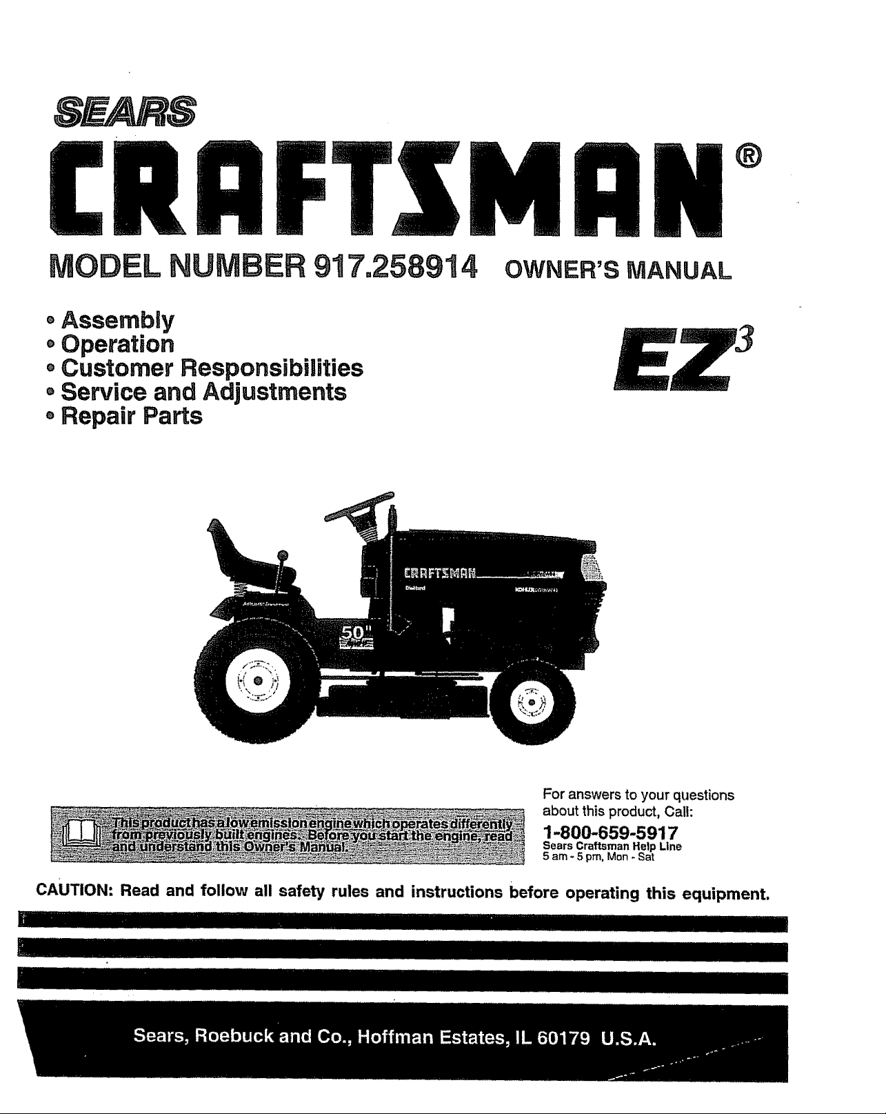
MODEL 917.258914
®Assembly
• Operation
Customer Responsibilities
Service and Adjustments
, Repair Parts
OWNER'S MANUAL
For answers to your questions
about this product, Call:
1-800-659-5917
Sears CraftsmanHelp Line
5 am - 5 pro, Mon - Sat
CAUTION: Read and follow all safety rules and instructions before operating this equipment.
Page 2
SAFETY RULES
£k
Safe Operation Practices for Ride-On Mowers
IMPORTANT: THIS CUTTING MACHINE IS CAPABLE OF AMPUTATING HANDS AND FEET AND THROWING OBJECTS
FAILURE TO OBSERVE THE FOLLOWING SAFETY INSTRUCTIONS COULD RESULT IN SERIOUS iNJURY OR DEATH
L GENERAL OPERATION
° Read, understand, and follow all instructlonsinthe manual
and on the machine before starting.
= Only allow responsible adults, who are familiar with the
instructions, to operate the machine°
• Clear the area of objects such as rocks, toys, wire, etc,,
which could be picked up and thrown by the blade°
. Be surethe area isclear of other people before mowing Stop
machine if anyone enters the area.
= Never carry passengers,
° Do not mew in reverse unless absolutely necessary, Always
look down and behind before and while backing.
• Be aware of the mower discharge direction and do not point
it at anyone° Do not operate the mower without either the
entire grass catcher or the guard in place,
° Slow down before tumingo
• Never leave a running machine unattended° Alwaysturnoff
blades, set parking brake, stop engine, and remove keys
before dismounting°
- Turn off blades when not mowing
° Stop engine before removing grass catcher or unclogging
chute.
. Mow only in daylight or good artificial light
° Do not operate the machine while under the influence of
alcohol or drugs°
• Watch for trafficwhen operating near orcrossingroadways°
• Use extra care when loading or unloadingthe machine into
atrailer ortruck°
IL SLOPE OPERATION
Slopes are a major factor related to loss-of-control and
tipover accidents, which can result in severe injury or death.
All slopes require extra caution, if you cannot back up the
slope or ff you feel uneasy on it, do not mow it.
DO:
• Mow upand down slopes, not across°
o Remove obstacles such as rocks,tree limbs, etc.
• Watch for holes, ruts, or bumps. Uneven terrain could
overturnthe machine. Taft grass can hide obstac/es.
o Use slowspeed, Choose a low gear so thatyou willnothave
tostop or shift while on the slope,
= Follow the manufacturer's recommendations for wheel
weights or counterweights to improve stability.
= Use extra care with grass catchers or other attachments°
These can change the stability ot the machine.
Keep all movement on the s!opess!owand gradual Do not
make sudden changes in speed or direction.
° Avoid starting or stopping on a slope° Iftires lose traction,
disengage the blades and proceed slowly straight down the
slope°
DO NOT:
. Donor turnonslopes unless necessary, and then,turnslowly
and gradually downhill, ifpossible.
° Do not mow near drop-offs, ditches, or embankments. "Fne
mower could suddenly turn over if a wheel is over the edge
ofa cliff or ditch, or ifan edge caves In.
o Do not mow on wet grass Reduced traction could cause
sliding.
. Do not try to stabilize the machine byputting your foot on the
ground°
° Do not use grass catcher on steep slopes.
IlL CHILDREN
Tragic accidents can occur if the operator is not alert to the
presence of children. Children are often attracted to the
machine and the mowing activity. Never assume that
children will remain where you last saw them.
Keep children out ofthe mowing area and under the watchful
care of another responsible adult.
o Be alert and turn machine off if children enter the area,
° Before and when backing, look behind and down for small
children.
° Never carry children,, They may fall off and be seriously
injured or interfere with safe machine operation_
° Never allow children to operate the machine°
• Use extra care when approaching blind comers, shrubs,
trees, or other objects that may obscure vision.
IV. SERVICE
- Use extra care In handling gasoline and other fuels, They are
flammable and vapors are explosive.
Use only an approved container.
Never remove gas cap or add fuel with the engine
running, Allow engine to cool before refueling, Do not
smoke.
- Never refuel the machine indoors.
- Never store the machine or fuel container inside where
. Never run a machine inside a closed area°
o Keep nuts and bolts, especially blade attachment botts, tight
° Never tamper with safety devices Check their proper
o Keep machine free of grass, leaves, or other debris build-upo
o Stop and inspect the equipment ff you strike an object,
° Never make adjustments or repairs with the engine running
= Grass catcher componentsare subject towear, damage, and
° Mower blades are sharp and can cut. Wrap the blade(s) or
° Check brake operation frequently. Adjust and service as
there is an open flame, such as a water heater°
and keep equipment in good condition_
operation regularly_
Clean oil or fuel spillage° Allow machine to cool before
storing°
Repair, if necessary, before restarting.
deterioration, which could expose moving parts or allow
objects to be thrown. Frequently check components and
replace with manufacturer's recommended parts, when nec-
essary.
wear gloves, and use extra cautionwhen servicing them.
required.
cAUTION: Always disconnect spark plug
wire and place wire where it cannot contact
spark plug In order to prevent accidental
starting when setting up, transporting,
...............................adjusting or making repairs,
................. i
..........A WARNING A
The engine exhaust from this product con-
tains cnemicats Known to the State of Cakfor-
nia to cause cancer, birth defects, or other
reproductive harm,
i,i, , I 'UU I I "lllll !ll!ll , , I lllll' 'lllll I
Page 3

CONGRATULATIONS on your purchase of a Sears
Tractor+ Ithas been designed, engineered and manufac-
PRODUCT SPECiFiCATiONS
HORSEPOWER: 22+5
tured to give you the best possible dependability and
performance.
Should you experience any problem you cannot easily
remedy, please contact your nearest Sears Authorized
Service Center/Department Department. W_ehave.com-
petent, well-trained technicians and the proper tools to
service or repair this tractor.
GASOLINE CAPACITY 3.5 GALLONS
AND TYPE: UNLEADED REGULAR
OIL TYPE (API+SF/SGiSH): SAE 10W30 (above 32°F)
SAE 5W-30 (below 32=F)
OIL CAPACITY: W/FILTER: 4,2 PINTS
W/O FILTER: 3°7 PINTS
Please read and retain this manual The instructions wilt
enable you to assemble and maintain your tractor properly°
Always observe the "SAFETY RULES".
MODEL
NUMBER
917.258914
SPARK PLUG: CHAMPION RC12YC
(GAP: +030")
VALVE CLEARANCE: NOT ADJUSTABLE
GROUND SPEED (MPH): FORWARD: 0- 5.8
REVERSE: 0- 2.1
SERIAL
NUMBER
DATEOF PURCHASE
THE MODEL AND SERIAL NUMBERS WILL BE FOUND
ON A PLATE UNDER THE SEAT,,
YOU SHOULD RECORD BOTH SERIAL NUMBER AND
DATE OF PURCHASE AND KEEP IN A SAFE PLACE
FOR FUTURE REFERENCE.
MAONTENANCE AGREEMENT
A Sears Maintenance Agreement isavailable on thisprod-
uct. Contact your nearest Sears storefor details.
TIRE PRESSURE: FRONT: 14 PSI
REAR: 10 PSI
CHARGING SYSTEM: I5 AMPS @ 3600 RPM
BATTERY: AMP/HR: 35
MIN° CCA: 280
CASE SIZE: UIR
BLADE BOLT TORQUE: 27-35 FT. LBS+
WARNING; This tractor is equipped with an internal
combustion engine and should not be used on or near any
unimproved forest-covered, brush-covered or grass-cov-
ered land unless the engine's exhaust system is equipped
with a spark arrester meeting applicable local or state laws
(if any). Ifa spark arrester is used, it should be maintained
CUSTOMER RESPONSiBiLiTiES
= Read and observe the safety rules.
- Followa regularschedule inmaintaining,caringforand
using your tractor.
o Follow the instructionsunder"Customer Responsibili-
ties" and "Storage" sections of this owner's manual°
,%[j- i i,iii,iiii I_'_I ±H ±UW I I "II 'I' '"'III 'I'I"'"'I'I"I'
in effectiveworking order by the operator°
In the state of California the above is required by law
(Section 4442 of the California Pubfic Resources Code).
Other states may have similar laws. Federal laws apply on
federal lands. A spark arrester for the muffler is available
through your nearest Sears Authorized Service Center
Department (See REPAIR PARTS section ofthis manual).
LIMITED TWO YEAR WARRANTY ON CRAFTSMAN RiDiNG EQUIPMENT
Fortwo(2)yearsfromthedateof purchase,ifthisCraftsmanRidingEquipmentismaintained,lubricatedand tunedupaccording
tothe tnstrucUonsinthe owner'smanual,Searswillrepairor replace,freeof charge,any partsfoundtobe defectivein matedal
orworkmanship+
ThisWarrantydoesnotcover.
o Expendableitemswhichbecomewornduringnormaluse, suchas blades,sparkplugs,air cleaners,betts,etc°
= Tire replacementor repaircaused bypuncturesfromoutsideobjects,suchas nails,thorns,stumps, or glass_
o Repairsnecessarybecauseofoperatorabuse,negligence,improperstorageor accidentor the failure to maintainthe
equipmentaccordingtotheinstructionscontainedin the owner's manual
° Riding equipmentused forcommercialor rentalpurposes+
LIMITED 90 DAY WARRANTY ON BATTERY
Forninety(90) days from dateofpurchase,if any battery includedwiththis ridingequipmentprovesdefectivein matedal or
workmanshipandourtestingdeterminesthebatterywillnotholda charge,Searswillreplacethebatteryatno charge,
IN-HOME WARRANTY SERVICE ON YOUR CRAFTSMAN RIDING EQUIPMENT IS AVAILABLE AT NO-CHARGE FOR 30
DAYS FROM THE DATE OF PURCHASE, PLEASE CONTACT YOUR NEAREST SERVICE CENTER. AFTER 30 DAYS
FROM THE DATE OF PURCHASE, WARRANTY SERVICE IS AVAILABLE BY TAKING YOUR CRAFTSMAN RIDING EQUIP-
MENT TO YOUR NEAREST SEARS SERVICE CENTER. (IN+HOME WARRANTY SERVICE WILL STILL BE AVAILABLE
AFTER 30 DAYS FROM THE DATE OF PURCHASE BUT A STANDARD TRIP CHARGE WILL APPLY,,) THIS WARRANTY
APPLIES ONLY WHILE THIS PRODUCT IS INTHE UNITED STATES_
This Warranty gives you specific legal rights,and you may also have other dghts which may vary from state to state+
......... I i ,11'11111 , II ii1,11,1,1, , I I I iii i,i1,,i,, i,iiii
SEARS, ROEBUCK AND CO., 13/817WA, HOFFMAN ESTATES, IL 60'179
Page 4
TABLE OF CONTENTS
=............. H! '1 I'lll ,llLI I_l' I I'/II"' '" ........ -N
SAFETY RULES ............................................................ 2
PRODUCT SPECIFICATIONS ...................................... 3
CUSTOMER RESPONSIBILITIES ..................... 3, 16.19
WARRANTY ..................................................... _............ 3
TRACTOR ACCESSORIES ..................................... 5,15
ASSEMBLY .............................................................. 7-10
OPERATION ........................................................... 12-16
MAINTENANCE SCHEDULE ...................................... t7
SERVICE AND ADJUSTMENTS ............................ 21-27
STORAGE ................................................................... 28
TROUBLESHOOTING ............................................ 29-30
REPAIR PARTS - TRACTOR ................................. 32-50
REPAIR PARTS - ENGINE .................................... 51-58
PARTS ORDERING/SERVICE ................ BACK COVER
INDEX
A
Accessories ..............................................................5
Adjustments:
Brake ...............................................................23
Carburetor ................................................27
Clutch Pulley ..............................................23
Gauge Wheels .........................................I4
Mower
Front-To-Back ...............................22
Side-To-Side ....................................21
Throttle Control Cable ..........................27
Air Filter, Engine ....................................................20
Air Screen, Engine .....................................19
Assembly .....................................................7-I0
B
Battery:
Charging .....................................................8
Cleaning ................................................20
Starting with Weak Battery ................25
Storage ......................................................28
Terminals .................................................i 9
Belt:
Motion Drive
RemovaVReplacement ................24
Mower Drive
RemovaVReplacement ..................22
Mower Blade Drive
Removal/Replacement ...............23
Blade:
Sharpening ...............................................18
Replacement ...........................................18
Brake Adjustment ..........................................23
C
Carburetor Adjustment ..................................27
Clutch Pulley ...................................................23
Controls,'Tractor ......................................12
Customer Responsibilities ..................t7-20
Engine:
Air Filter..............................................20
Air Screen .........................................19
Cooling Fins .....................................20
Engine Oil ..................................15,19
Fuel Filter ...........................................20
Spark Plug(s) ...................................20
Tractor:
Battery .............................................18
Blade .............................................18
LubricationChart ..............................17
Maintenance Schedule .............17
Tire Care ....................................8,18,25
Transaxle ........................................19
Cutting Height, Mower ...................................13
E
Electrical:
Interlocks and Relays ............................26
Schematic .....................................................31
Wiring Diagram ..........................................32
Engine:
Air Filter ..................................................20
Air Screen .............................................19
Cooling Fins .........................................20
Oil Change ..............................................19
Oil Level ...............................................15
OI1Type ........................................15,19
Preparation ................................................15
Repair Parts .......................................51-58
Starting.................................................15-16
Storage ...............................................25
F
Filten
Air Filter ...........................................................20
Fuel ....................................................................20
Oil...................................................................20
Fuel:
Storage ..............................................................28
Type ...................................................................t 5
Fuse ............................................................................26
H
Headlights .............................................................26
Hood Removal/Installation .......................26
M
Maintenance Schedule .............................17
Mower:.
Adjustment, Front-to-Back ..............22
Adjustment, Side-to-Side ................2t
Blade Replacement .........................18
Blade Sharpening ................................18
Cutting Height ......................................13
Installation................................................2!
Operation .................................................14
Removal .................................................21
Mowing Tips ..................................................t6
Muffler ....................................................................20
Spark Arrester ....................................3,40
O
Oil:
Cold Weather Conditions ...........15,t9
Engine ............................................................19
Storage ..........................................................28
4
Operation .......................................................12_I6
Operating Mower ............................................14
Options:
Accessories ..............................................5
Spark Arrester ..................................... 3,40
P
Parking Brake .....................................................13
Parts Bag ..............................................................6
Parts, Replacement/Repair ................32-50
Product Specifications ...................................3
R
Repair Parts ...........................................32-50
S
Safety Rules .......................................................2
Seat .........................................................................8
Service and Adjustments .................21-27
Carburetor ................................................27
Clutch Pulley ..........................................23
Fuse ........................................................26
Hood RemovaVlnstallation ................26
Motion Drive Belt
Removal/Replacement ....................22
Mower Drive Belt
Removal/Replacement ..................22
Mower Blade Drive Belt
Removal/Replacement ................23
Mower Adjustment
Front-to-Back ..................................22
Side-to-Side ....................................21
Mower Removal/Instalfation ..........21
Tire Care ........................................8,16,25
Slope Guide Sheet .....................................59
Spark Plug(s) .................................................20
Specifications ....................................................... 3
Starting the Engine ................................. 15-16
Steering Wheel ............................................7,24
Stopping the Tractor .......................................13
Storage ...............................................................28
T
Throttle Control Cable Adjustment ........27
Tires ...............................................................8,18,25
Troubleshooting Chart .........................29_30
Transaxle ...........................................................19
W
Warranty ...................................................................3
Wiring Diagram .............................................32
Wiring Schematic ..........................................31
Page 5
ACCESSORNES AN ATTACHMENTS;
-- _..._,........................... ,,, ..................... , r, ,,,r,,_,,'...................... ,,,.......
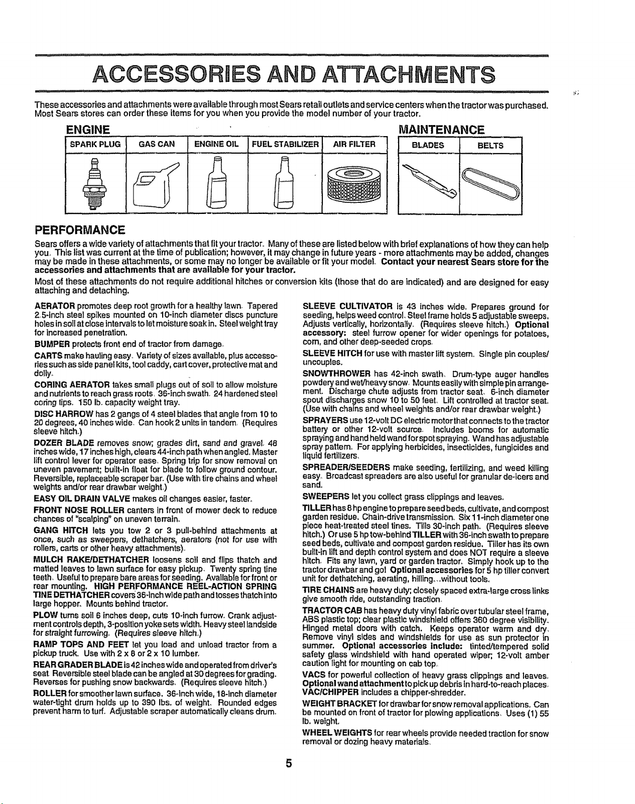
These accessories and attachments were available throughmost Sears retail outlets and service centers when the trectorwas purchased,
Most Sears stores can order these items for you when you provide the model number of your tractor.
ENGINE
SPARKPLUG GAS CAN AIR FILTERENGINEOIL FUEL STABILIZER
PERFORMANCE
Sears offersa wide variety of attachments that fit yourtractor., Many of these are listedbelow with brief explanations of how they can hefp
you, Thts tist was currentat the time of publication;however, itmay change !n future years - more attachments may be added, changes
may be made inthese attachments, orsome may no longer be available ortit your model, Contact your nearest Sears store for the
accessories and attachments that are available for your tractor.
Most of these attachments do not require additionalhitches or conversionkits (those that do are indicated) and are designed for easy
attaching and detaching.
AERATOR promotes deep rootgrowth for a healthy lawn. Tapered
2,5-Inch steel spikes mountedon 10-inch diameter discspuncture
holes insoilatcloseintervalstoletmoisture soakIn. Steelweighttray
for increasedpenetration.
BUMPER protectsfront end of tractorfrom damage°
CARTS makehaulingeasy_Varietyof sizes available, plusaccessm
dessuchasside panelkits,toolcaddy,cartcover, protectivematand
dolty_
CORING AERATOR takes small plugsoui of soil toattow moisture
andnutrientsto reach grass roots, 36-inchswath, 24hardenedsteel
codng tips. 150 lb. capacity weighttray.
DISC HARROW has 2gangs of 4steel blades that anglefrom 10 to
20degrees, 40 incheswide, Can hook 2units intandem, (Requires
Sleevehitch°)
DOZER BLADE removes snow; grades dirt, sand and gravel 48
incheswide,!7 incheshigh,clears44-inchpathwhenangled, Master
liftcontrollever for operator ease, Spdngtdpfor snowremovalon
uneven pavement;buitt-fnfloat for blade to foltow groundcontour.
Reversible,replaceablescraperbar. (Use withtirechainsandwheel
weightsand/or reardrawbar weight.)
EASY OIL DRAIN VALVE makesoilchanges easier,faster°
FRONT NOSE ROLLER canterstn front ofmower deck to reduce
chancesof "scalping" onuneventerrain°
GANG HITCH lets you tow 2 or 3 puf!-behindattachments at
once, such as sweepers, dethatchers, aerators (not for use w_th
rolIers,cartsorotherheavy attachments)°
MULCH RAKFJDETHATCHER loosens soil andflips thatch and
matted leaves to lawnsurface for easy pickup. Twentyspringtins
teeth. Usefulto preparebare areas for seeding. Availableforfront or
rear mounting. HIGH PERFORMANCE REEL-ACTION SPRING
TINE DETHATCHER covers36-1nchwidepathandtossesthatchinto
large hopper° Mountsbehind tractor,,
PLOW turnsso]l 6 inches deep, cuts10-inchfurrow. Crank adjust-
meritcontrolsdepth,3-positionyokesets width,Heavysteeltandside
forstraight furrowing. (Requiressteers hitch.,)
RAMP TOPS AND FEET let you load and unload tractorfrom a
pickuptruck,,Use with2 x 8 or 2 x 10 lumber.
REARGRADER BLADEis42 incheswideand operatedfrom driver's
seat Reversiblesteel bladecanbe angled at30 degreesforgrading_
Reversesfor pushingsnowbackwards. (Requiressleeve hitch,)
ROLLERforsmootherlawnsurface. 364nch wide, 18-Inchdiameter
water-tightdrum holdsup to 390 Ibs°of weight. Roundededges
preventharm toturf° Adjustable scraperautomaticallycleansdrum.
SLEEVE CULTIVATOR is 43 inches wide. Prepares ground for
seeding, helps weedcontrol.Steelframe holds5 adjustablesweeps,
Adjusts vertically,horizontaliy, (Requires sleeve hitch.) Optional
accessory: steel furrow openerfor wider openings for potatoes,
corn,and otherdeep-seeded crOpSr
SLEEVE HITCHfor use with masterlift system. Singlepincouples/
uncouples.
SNOW'THROWER has 42-inchswath,, Drum-type auger handles
powderyandwet/heavysnow Mountseasilywithsimplepinarrange-
ment. Dischargechute adjusts from tractorseat. 6-inch diameter
spout dischargessnow I0 to 50 feel Liftcontrolledat tractorseat.
(Use withchainsand wheel weightsand/or reardrawbar weighL)
SPRAYERS use12-volt DOelectricmotor that connectstothetractor
battery or other 12-volt source, Includes booms for automatic
spraying andhandheldwandforspotspraying_Wand hasadjustable
spray pattern, Forapplyingherbicides,insecticides,fungicides and
liquid fertilizers.
SPREADERff3EEDERS make seeding, fertilizing,and weed killing
easy° Broadcast spreaders are alsousefulfor granularde-icers and
sand°
SWEEPERS letyou collectgrassclippingsand leaves°
TILLERhas8hpenginetoprepareseedbeds,cultivate,andcompost
gardenresidue.Chain-drivetransmisston.SIx1l-inchdiameterone
pieceheat-treatedsteeltines.Tilts30-inchpath.(Requiressleeve
hitch.)Oruse5 hptow-behlndTILLERwith36-Lnchswathtoprepare
seedbeds,cultivateandcompostgardenresidue.Tillerhas itsown
buitt-inliftand depthcontrolsystemanddoes NOT requirea sleeve
hitch.Fitsanylawn,yardorgardentractor°Simplyhookup tothe
tractor drawbar andgol Optional accessories for 5 hp tiller convert
unitfor dethatchtng,aerating, hlllingo,.withouttools.
TIRE CHAINS areheavyduty;closelyspaced extra4argecrosslinks
give smooth ride,outstandingtraction.
TRACTOR CAB has heavy dutyvinylfabricovertubularsteel frame,
ABS plastictop;clearplasticwindshieldoffers 360 degreevisiblIityo
Hinged metal doors with catch. Keeps operator warm and dry,
Remove vinylstdes and windshieldsfor use as sun protector tn
summer. Optional accessories include: tinted/temperedsolid
safety glass windshieldwith hand operated wiper;, t2wolt amber
cautionlight for mountingon cab top,
VACS for powerfulcollectionof heavy grass clippings and leaves,
Optional wand attachment topickupdebdstnhard-to-reachplaces.
VAC/CHIPPER includesa chipper-shredder,
WEIGHT BRACKET fordrawbarfor snow removalapplications,Can
be mountedonfront oftractorfor plowingapplications, Uses (1) 55
Ib, weight.
WHEEL WEIGHTS for rearwheelsprovideneededtractionfor snow
removalor dozingheavymaterials.
MAINTENANCE
BLADES BELTS
5
Page 6
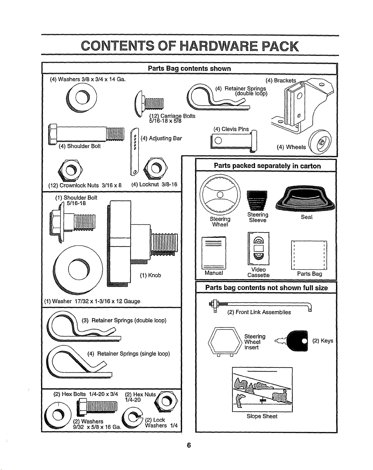
CONTENTS OF HARDWARE PACK
,i,,, I_L ;,_ :- ............. _l_,rl¸ i,ii , ,,i. ,, n,n,ll i ..... ; .......... , ,r,ll,i i ,. i......
Parts Bag contents shown
(4) Washers 3/8 x 3/4 x 14 Ga.
2) Carriaqe Botts
16-18 x 578
(4) Adjusting Bar
(4) Shoulder Bolt
e
(4) Wheels
,,,i ...........
(12) Crownlock Nuts 3/16 x 8
(4) Locknut 3/8-16
(1) ShoulderBolt
5/16-18
(1) Washer 17/32 x 1-3/16 x 12 Gauge
in ..... '1". i_
(1) Knob
Steering
Steering Seat
Sleeve
Wheel
Video ............
Manual Cassette Parts Bag
Parts bag contents not shown full size
_(2) Front Link Assemblies
Wheel
_ teering
Insert
(2) Keys
(2) Hex Bolts 1/4-20 x 314 (2) Hex NutsjC_=_k
. _ 1/4-20 [ _
"J i/(2) Washers L. _ (2)Lock _...
_ 9/32 x 5/8x 16 Ga, "_ vvasners ]/4
Slope Sheet
6
Page 7
LY
L HJ[llnl ,,_, ........... ............ ,. : m' I i I 11...... i
Your new tractor has been assembled at the factorywith the exception ofthose parts left unassembled for shipping purposes.
To ensure safe and proper operation of your tractor all parts and hardware you assemble must be tightened securely,. Use
the correct tools as necessary to insure proper tightness.
TOOLS REQUIRED FOR ASSEMBLY
A socket wrenchset wiltmake assembly easier_ Standard
wrench sizes are listed,
(2) 7/16" wrenches Tire pressure gauge
(1) 1/2" wrench Utility knife
(1) 9/t6" wrench
(1) 3/4" socket with drive ratchet
When right or left hand is mentioned in this manual, it
means when you are in the operating position (seated
behind the steering wheel).
TO REMOVE TRACTOR FROM CARTON
UNPACK CARTON
o Remove all accessible loose parts and parts cartons
from carton (See page 6).
o Cut, from top to bottom, along lines on all four corners
of carton, and lay panels flat.
° Check for any additional loose parts or cartons and
remove.
BEFORE ROLLING TRACTOR OFF SKID
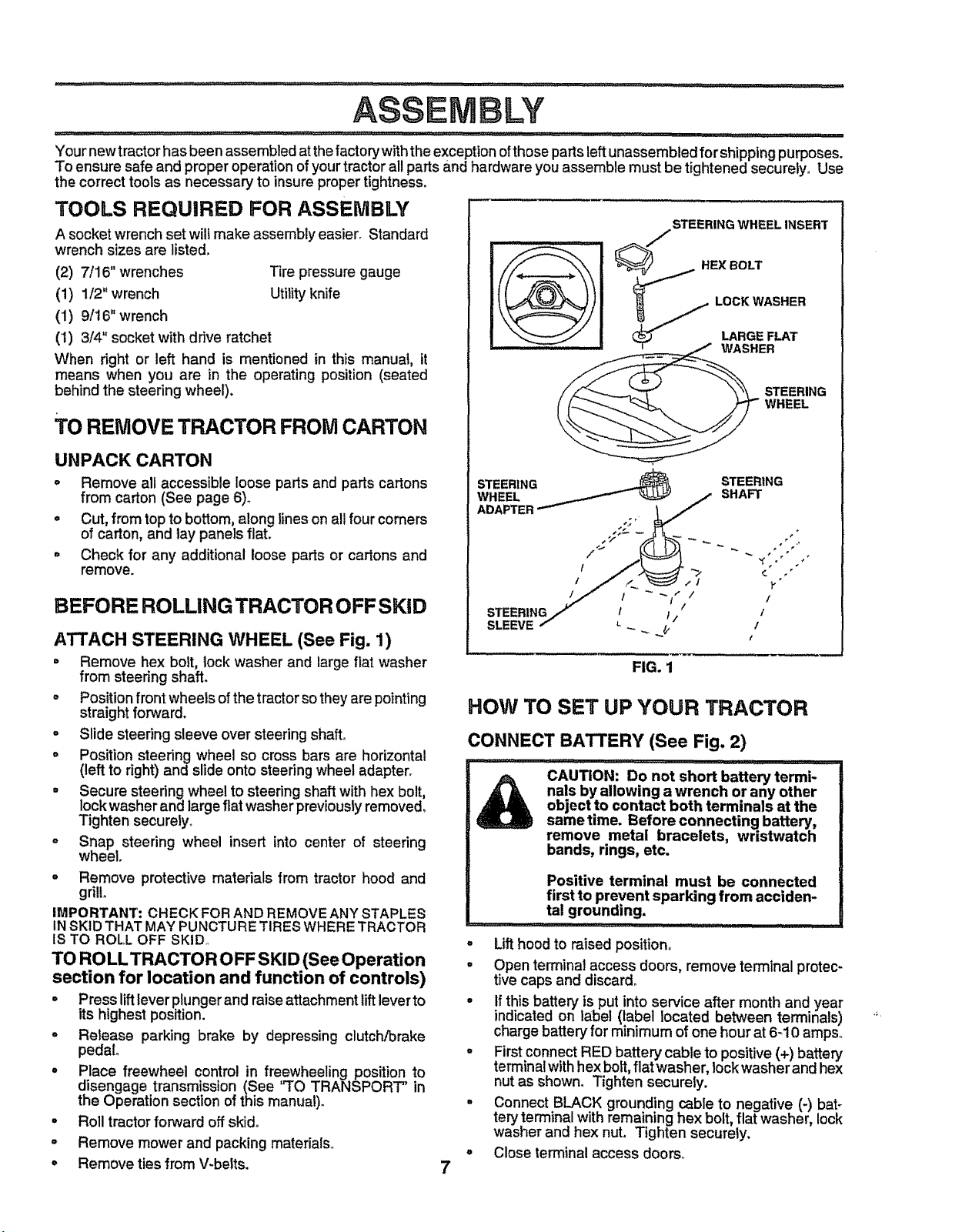
ATTACH STEERING WHEEL (See Fig. 1)
° Remove hex bolt, lock washer and largeflat washer
from steering shaft.
o Position front wheels of the tractor sothey are pointing
straight forward.
° Slide steering sleeve over steering shaft.
° Position steering wheel so cross bars are horizontal
(left to right)and slide onto steering wheel adapter°
= Secure steering wheel to steering shaft with hex bolt,
lock washer and large flat washer previously removed,
Tighten securety_
o Snap steering wheel insert into center of steering
wheel,
o Remove protective materials from tractor hood and
grill
IMPORTANT: CHECK FORAND REMOVE ANY STAPLES
tN SKID THAT MAY PUNCTURETIRES WHERE TRACTOR
IS TO ROLL OFF SKID.,
TO ROLL TRACTOR O FF SKID (See Operation
section for location and function of controls)
° Press liftlever plungerand raiseattachment lift leverto
itshighest position.
° Release parking brake by depressing clutch/brake
pedal
° Place freewheel control in freewheeling position to
disengage transmission (See "TO TRANSPORT" in
the Operation section of this manual).
o Roll tractor forward off skid°
= Remove mower and packing materials°
o Remove ties from V-belts.
STEERING
WHEEL
ADAPTER
STEERING t t /
SLEEVE _ _, ,,
HOW TO SET UP YOUR TRACTOR
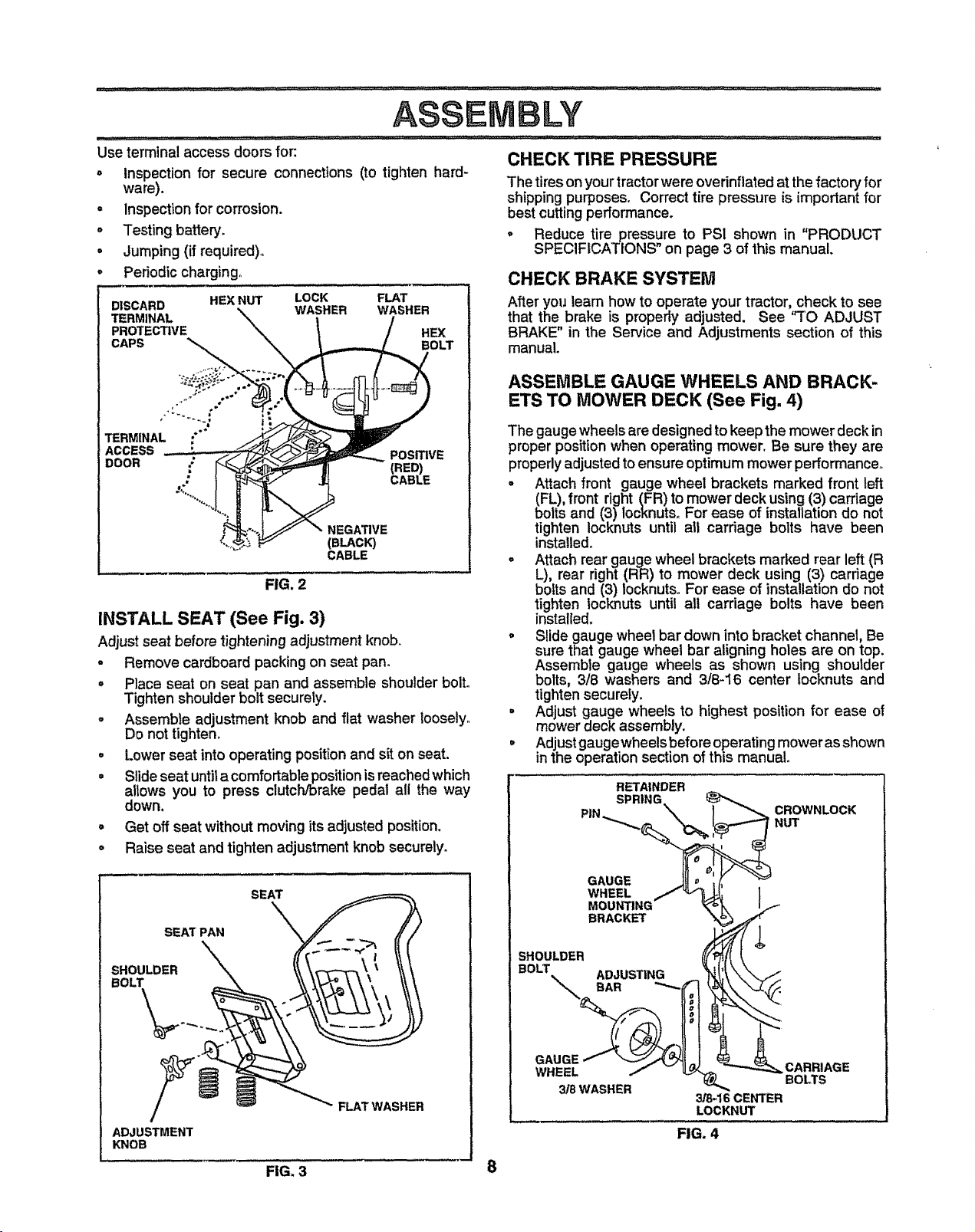
CONNECT BATTERY (See Fig. 2)
i11 ,lll][Lll,l _ I , i1,,,,i, I ,, i .... !,1/! i i1,1,,, ,,,,i,,11,I......
CAUTION: Do not short battery termi-
nals by allowing a wrench or any other
object to contact both terminals at the
same time. Before connecting battery,
remove metal bracelets, wristwatch
bands, rings, etc.
Positive terminal must be connected
first to prevent sparking from acciden-
tal grounding.
o
Lift hood to raised position.
o
Open terminal access doors, remove terminal protec-
tive caps and discard_
° if this battery isput into service after month and year
indicatedon label (label located between terminals)
charge batter),"for minimum of one hour at 6-10 ampso
° First connect RED battery cable to positive (+) battery
terminal with hex bolt, flat washer, lock washer and hex
nut as shown° Tighten securely.
° Connect BLACK grounding cable to negative (-) bat-
tery terminal with remaining hex bolt, flat washer, lock
washer and hex nut. Tighten securely.
° Close terminal access doors°
7
STEERING WHEEL INSERT
STEERING
SHAFT
I
/
FIG. 1
Y
/
/
/
/
Page 8
BLY
g!l'l"l' _,_ ...... ....... _ .,.,,,.........,,,....,., + ,_ : • ,,+,, , i p I ,, ,,ii
Use terminal access doors for: CHECK TIRE PRESSURE
° Inspection for secure connections (to tighten hard-
ware).
= inspection for corrosion.
+ Testing battery.
• Jumping (if required).
Periodic charging.
DISCARD -,_ WASHER WASHER
PROTECTIVE HEX
CAPS OLT
HEX NUT LOCK FLAT
The tires onyour tractor were ovednflatedat the factory for
shipping purposes. Correct tire pressure is important for
best cutting performance.
° Reduce tire pressure to PSI shown in "PRODUCT
SPECIFICATIONS on page 3 of this manual.
CHECK BRAKE SYSTEM
After youlearn how to operate your tractor, check to see
that the brake is properly adjusted. See 'q"O ADJUST
BRAKE" in the Service and Adjustments section of this
manual.
•+-,,_+;: + • .+ ........
.++ ++.
++,+++......
a •
TERMINAL ;*
ACCESS ..... > _'._
• CABLE
_'_+_+__ CABLE
"_"NEGATIVE
(BLACK)
FIG. 2
roVE
INSTALL SEAT (See Fig. 3)
Adjust seat before tightening adjustmentknob+
o Remove cardboard packing on seat pan.
= Place seat on seat pan and assemble shoulder bolto
Tighten shoulder bolt securety.
o Assemble adjustment knob and flat washer loosely,
Do nottighten,
o Lower seat into operating positionand sit on seat.
= Slideseat untila comfortable positionisreached which
altows you to press clutch/brake pedal all the way
down.
° Get offseatwithoutmovingitsadjustedposition,
° Raise seat and tighten adjustment knob securely.
ASSEMBLE GAUGE WHEELS AND BRACK-
ETS TO MOWER DECK (See Fig. 4)
The gauge wheels are designed to keep the mower deck in
proper position when operating mower. Be sure they are
propedy adjusted to ensure optimum mower performance°
- Attach front gauge wheel brackets marked front left
(FL), front right (FR) to mower deck using (3) carriage
bolts and (3) locknuts. For ease of installation do not
tighten Iocknuts until all carriage bolts have been
installed°
° Attach rear gauge wheel brackets marked rear left (R
L), rear right (RR) to mower deck using (3) carriage
bolts and (3) locknuts,For ease of installation do not
tighten Iocknuts until all carriage bolts have been
installed.
o Slide gauge wheet bar down into bracket channel, Be
sure that gauge wheel bar aligning holes are on top.
Assemble gauge wheels as shown using shoulder
bolts, 3/8 washers and 3/8-16 center tocknuts and
tighten securely.
= Adjust gauge wheels to highest position for ease of
mower deck assembly.
° Adjust gaugewheels before operating mower as shown
in the operation section of this manual.
RETAINDER
plm SPRING,\ _ CROWNLOCK
"_ NUT
SEAT
SHOULDER _,, _\ \¢'T"T_ \ ' \\ \
____. FLAT WASHER
ADJUSTMENT
KNOB
FIG, 3 8
GAUGE .,]Uo ;(
WHEEL /_'_ ]
MOUNTING _o ,_ I._
BRACKET
SHOULDER _P_/rl _
BOLT ADJUSTING _t!_ \._. /
il'i "
GAUGE (;_
WHEEL ./ _ _._, _-_CARRIAGE
3/8 WASHER _ BOLTS
3/8-16 CENTER
LOCKNUT
FIG. 4
Page 9

LY
INSTALL MOWER AND DRIVE BELT = Place the suspension arms on inward pointing deck
(See Figs. 5 and 7) pins. If necessary, rock and raise front of mower to
Be sure tractor is on level surface and mower suspension Retain with double loop retainer springs with loops
arms are raised with attachment lift control, Engage park- down as shown.
ingbrake. °
o Cut and remove ties securing anti-sway bar and belts
Swing antFsway bar to leftside of mower deck.
- Slide mower undertractorwith discharge guardto right
side of tractor, o
IMPORTANT: CHECK BELT FOR PROPER ROUTING iN
ALL MOWER PULLEY GROOVES. INSTALLBELT INTO
ELECTRIC CLUTCH PULLEY GROOVE°
° Install one front linkintop holeofthe L.H. front mower
bracket and LH,,front suspension bracket. Retainwith
two single loop retainer springs as shown.
- installsecondfrontlinkin R.Hofrontsuspensionbracket
only and retain with single loop retainer spring as
shown.
o Slide right side of mower back and installlink intop hole
of RoHofront mower bracket. Retain with single loop
retainer spring as shown,
° Turn height adjustment knob counterclockwise until it
stops.
° Lower mower linkage with attachment lift control,
DOUBLE LOOP
RETAINER
CHASSIS SPRING (inward
BRACKET pointingdeck pins}
SUSPENSION
ARMS
align deck pins with the holes in suspension arms.
Connect anti-sway bar to chassis bracket under left
footrest and retain with double loop retainer spring,
°
Turn height adjustment knob clockwise to remove
slack from mower suspension.
Raise deck to highest position.
=
Adjust gauge wheels before operating mower asshown
in the Operation section of this manual,
CHECK MOWER LEVELNESS
Forbest cuttingresults,mower should be properlyleveled.
See "TO LEVEL MOWER HOUSING" in the Service and
Adjustments section ofthis manual.
CHECK FOR PROPER POSiTiON OF ALL
BELTS
See the figures thatare shown for replacing motion, mower
drive, and mower blade drive belts in the Service and
Adjustments section ofthis manual Verify that the belts are
routed correctly.
FRONT
SUSPENSION
BRACKETS
FRONT
MOWER
BRACKET
FRONT
ELECTRIC
CLUTCH
PULLEY
GAUGE
WHEEL
/
DOUBLE
LOOP
RETAINER
SPRING
SINGLE LOOP
RETAINER
SPRINGS
ANTI-SWAY
BAR
DISCHARGE
GUARD
/
IDLER
PULLEY
FIG. 5
9
Page 10
ASS
,/'CHECKLIST
BEFORE YOU OPERATE AND ENJOY YOUR NEW
TRACTOR, WE WISH TO ASSURE THAT YOU RECEIVE
THE BEST PERFORMANCEAND SATISFACTION FROM
THIS QUALITY PRODUCT.
PLEASE REVIEW THE FOLLOWING CHECKLIST:
v" All assembly instructions have been completed°
/ No remaining loose parts in carton°
,/ Battery is properly prepared and charged. (Minimum
t hour at 6 amps)_
J Seat is adjusted comfortably and tightened securely°
,/" All tires are properly inflated. (For shipping purposes,
the tires were overinflatedat the factory)°
,/ Be sure mower deck is properly leveled side4o-side/
front40-rear for best cutting results. (Tires must be
properly inflated for leveling)°
,z Check mower and drive belts. Be surethey are routed
properly around pulleys and inside all belt keepers.
,/ Check wiring. See that all connections are still secure
and wires are properly clamped.
J" Before driving tractor, be sure freewheel control is in
drive position._
WHILE LEARNING HOW TO USE YOUR TRACTOR, PAY
EXTRA ATTENTION TO THE FOLLOWING IMPORTANT
ITEMS:
J' Engine oil is at proper level.
,i Fuel tank is filled with fresh, clean, regular unleaded
gasoline.
•/" Become familiar with all controls - their location and
function. Operate them before you start the engine°
J Be sure brake system is in safe operating condition°
#" tt is important to purge the transmission before operat-
ingyour tractor for the first time. Follow proper starting
and transmissionpurging instructions(See,%..OSTART
ENGINE" and PURGE TRANSMISSION in the Op-
eration section of this manual),
LY
10
Page 11
O ATION
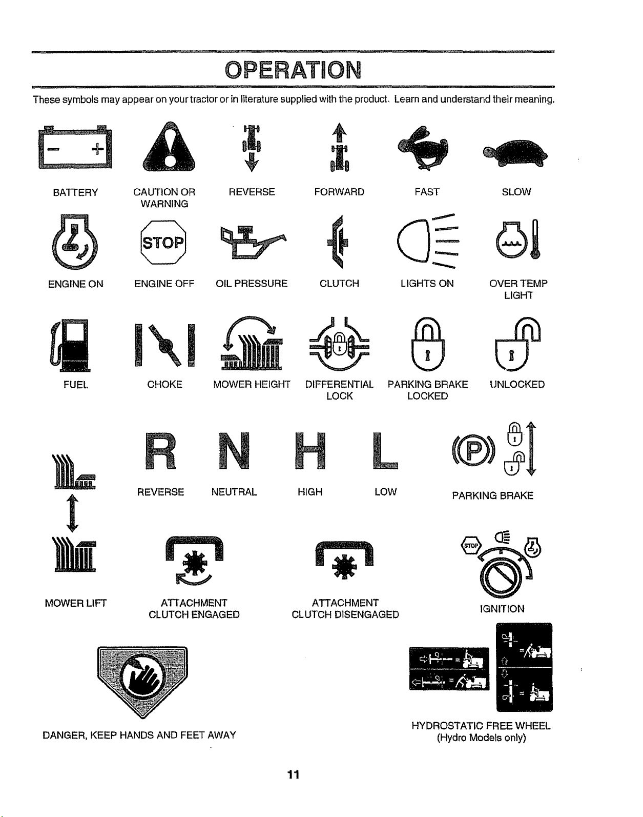
These symbols may appear onyour tractor or inliterature supplied with the product, Learn and understand their meaning.
BATTERY
WARNING
ENGINE ON
FUEL CHOKE MOWER HEIGHT DIFFERENTIAL PARKING BRAKE UNLOCKED
ENGINE OFF OIL PRESSURE CLUTCH OVER TEMP
REVERSECAUTION OR FORWARD SLOW
LOCK LOCKED
FAST
LIGHTS ON
L
LIGHT
REVERSE NEUTRAL
MOWER LIFT
DANGER, KEEP HANDS AND FEET AWAY
ATTACHMENT
CLUTCH ENGAGED
HIGH
ATTACHMENT
CLUTCH DISENGAGED
11
LOW PARKING BRAKE
IGNITION
HYDROSTATIC FREE WHEEL
(Hydro Models only)
Page 12
OPEBATION
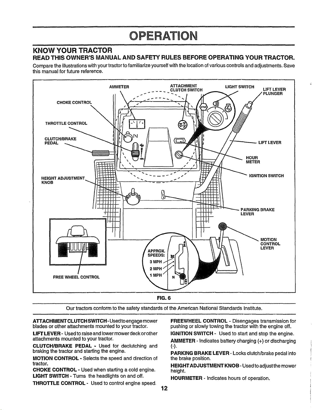
KNOW YOUR TRACTOR
READ THIS OWNER'S MANUAL AND SAFETY RULES BEFORE OPERATING YOUR TRACTOR.
Compare the illustrations with your tractor to familiarize yourself with the location of various controls and adjustments. Save
this manual for future reference.
CHOKE CONTROL
THROTTLE CONTROL
CLUTCH/BRAKE
PEDAL
HEIGHT ADJUSTMENT
KNOB
AMMETER ATTACHMENT LIGHT SWITCH
...... CLUTCH SWITCH
HOUR
METER
PARING BRAKE
LEVER
LIFT LEVER
PLUNGER
LtFT LEVER
IGNITION SWITCH
SPEEDS:
3 MPH
FREEWHEEL CONTROL
Our tractors conformto the safety standards of the American National Standards Institute.
AI"rACHMENT CLUTCH SWITCH- Used toengage mower
blades or other attachments mountedto your tractor.
LIFT LEVER- Usedto raiseand lowermowerdeck orother
attachments mountedtoyour tractor,
CLUTCH!BRAKE PEDAL - Used for declutching and
braking the tractorand starting the engine,
MOTION CONTROL - Selectsthe speed and direction of
tractor,
CHOKE CONTROL - Usedwhen starting a cold engine°
LIGHT SWITCH - Turns the headlightson and off,
THROI_LE CONTROL - Used tocontrolengine speed,
MOTION
CONTROL
LEVER
FIG. 6
FREEWHEEL CONTROL - Disengages transmission for
pushingor slowly towing the tractor withthe engine off.
IGNITION SWITCH - Used to start and stopthe engine.
AMMETER _Indicates battery charging (+) or discharging
PARKING BRAKE LEVER _Locksclutch/brakepedal into
the brake position°
HEIGHTADJUSTMENT KNOB- Usedto adjust the mower
height.
HOURMETER - Indicates hours of operation.
12
Page 13
OPERATION
in severe eye damage. Always wear safety glasses or eye shields while operating your tractor !
or performing any adjustments or repairs. We recommend a ,,vide vision safety mask over the |
....... spectacles or standard safety g!asses. ................. i
The operation ofany tractor can result in foreign objects thrown into the eyes, which can result I
HOW TO USE YOUR TRACTOR
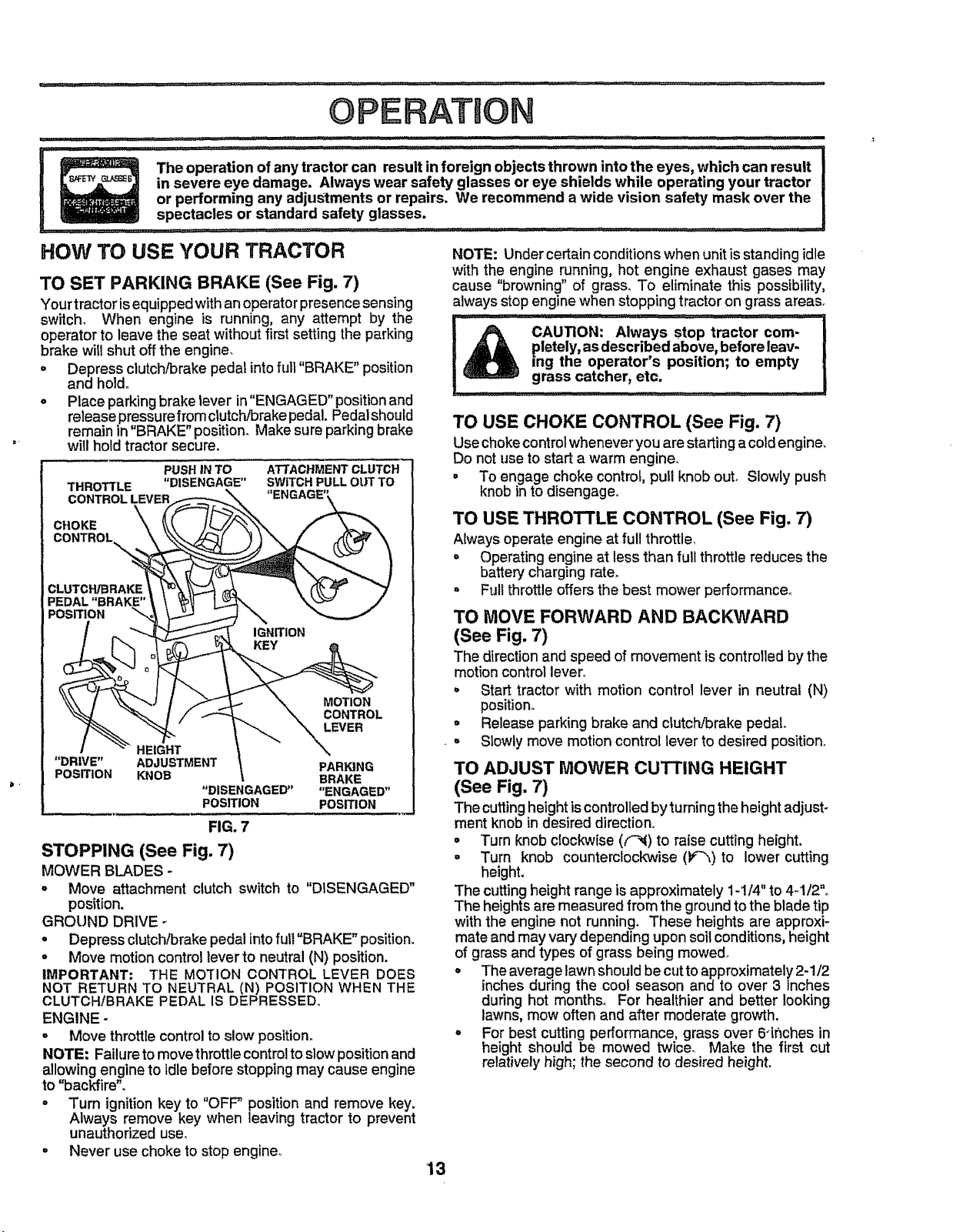
TO SET PARKING BRAKE (See Fig. 7)
Yourtractor isequippedwithan operatorpresencesensing
switch. When engine is running, any attempt by the
operator to leave the seat without first setting the parking
brake wiilshut offthe engine.
= Depress clutch/brake pedal into fult"BRAKE" position
and holdo
- Place parking brake lever in"ENGAGED" positionand
release pressure from clutch/brake pedal. Pedalshould
remain in "BRAKE" position. Make sure parking brake
will hold tractor secure,
PUSH IN TO ATTACHMENT CLUTCH
THROTTLE "DISENGAGE" SWITCH PULL OUT TO
CONTROL LEVER
CLUTCH/BRAKE
PEDAL "BRAKE"
POSITION _'_
IGNITION
MOTION
CONTROL
LEVER
HEIGHT
"DRIVE" ADJUSTMENT PARKING
POSITION KNOB BRAKE
"DISENGAGED .... ENGAGED"
POSITION POSITION
FIG. 7
STOPPING (See Fig. 7)
MOWER BLADES -
- Move attachment clutch switch to "DISENGAGED"
position.
GROUND DRIVE
° Depress clutch/brake pedal into full"BRAKE" position.
. Move motion control lever to neutral (N) position.
IMPORTANT: THE MOTION CONTROL LEVER DOES
NOT RETURN TO NEUTRAL (N) POSITION WHEN THE
CLUTCHIBRAKE PEDAL iS DEPRESSED,,
ENGINE -
o Move throttle control to slow position.
NOTE= Failure to movethrottle control to slow position and
allowing engine to idle before stopping may cause engine
to "backfire".
° Turn ignition key to "OFF' position and remove key.
Always remove key when leaving tractor to prevent
unauthorized use°
° Never use choke to stop engine,,
NOTE: Under certain conditions when unit is standing idle
with the engine running, hot engine exhaust gases may
cause "browning" of grass,, To eliminate this possibility,
always stop enginewhen stopping tractor on grass areas.
CAUTION: Always Stop tractor com-
pletely, as described above, before leav-
ing the operator's position; to empty
grass catcher, etc.
TO USE CHOKE CONTROL (See Fig. 7)
Usechokecontrolwhenever youare starting a coldengine.
Do notuse to start a warm engine
° To engage choke control, pull knob out_ Slowly push
knobin to disengage°
TO USE THROTTLE CONTROL (See Fig. 7)
Always operate engine at full throttle_
= Operating engine atless than full throttlereduces the
battery charging rate.
• Full throttleoffersthe best mower performance.
TO MOVE FORWARD AND BACKWARD
(See Fig. 7)
The direction and speed of movement iscontrolledby the
motion control lever_
o Start tractor with motion control lever in neutral (N)
position°
° Release parking brake and clutch/brake pedal
- Slowly move motion control lever to desired position.
TO ADJUST MOWER CUTTING HEIGHT
(See Fig. 7)
The cutting height iscontrolled by tuming the height adjust_
merit knob in desired direction.
= Turn knob clocl_wise (('_) to raise cutting height,
• Turn knob counterclockwise (F"_) to lower cutting
height.
The cutting height range is approximately 1-1/4" to 4-1/2"o
The heights are measured from the ground to the blade tip
with the engine not running. These heights are approxi-
mate andmay vary depending upon soil conditions, height
of grass and types of grass being mowed°
° The average lawn should be cut to approximately 2-1/2
inches during the coot season and to over 3 inches
during hot months. For healthier and better looking
lawns, mow often and after moderate growth.
° For best cutting performance, grass over 6"ihches in
height should be mowed twice., Make the first cut
relatively high; the second to desired height.
13
Page 14
OPERATION
TO ADJUST GAUGE WHEELS (See Fig. 8A)
Gauge wheels are properlyadjusted whenthey are slightly
offthe groundwhen moweris atthe desiredcuttingheight
in operatingposition.Gauge wheels then keep the deck in
proper position to help prevent scalping in most terrain
conditions.
• Be sure tractor is on a flat Ievel surface_
o Lower mower and adjust mower to desired cutting
height.
° Remove retainer spring and clevis pin which secure
each gauge wheel bar,,
• Lower gauge wheels to ground,, Raise gauge wheels
slightly to align holes in bracket and gauge wheel bar
and insert clevis pin° Gauge wheels should be slightly
off the ground°
o Replace retainer spring into clevis pin°
IMPORTANT; BE SURETO READJUST GAUGE WHEELS
IF YOU CHANGE THE CUTTING HEIGHTOFTHE MOWER
DECK.
RETAINER
SPRING
CLEVIS PIN
FIG. 8A
TO OPERATE MOWER (See Figs. 6 and 7)
Yourtractor isequipped with an operatorpresence sens-
ing switch° Any attempt by the operator to leave the seat
withtheengine runningandtheattachmentclutchengaged
willshut off the engine.
= Select desired height of cut.
. Lower mower withattachment lift control.
= Start mower blades by engaging attachment clutch
contro!.
° TO STOP MOWER BLADES - disengage attachment
clutch control.
TO OPERATE ON HILLS
I A ....CAu o.:00notdrlveupo,downI
hills with slopes greater than 15° and |
L ...... . ....... ........: .... !
o Choose the slowest speed before starting up ordown
hitts,,
o Avoid stopping or changing speed on hills,,
° If slowing is necessary, move throttle control lever to
slower position.
= if stopping is absolutely necessary, push clutch/brake
pedal quickly to brake position and engage parking
brake.
o Move motion control lever to neutral IN) position.,
IMPORTANT; THE MOTION CONTROL LEVER DOES
NOT RETURN TO NEUTRAL IN) POSITION WHEN THE
CLUTCH/BRAKE PEDAL IS DEPRESSED.,
• To restart movement, slowly release parking brake and
clutch/brake pedal°
° Slowly move motion control lever to slowest setting,
o Make all tums slowly.
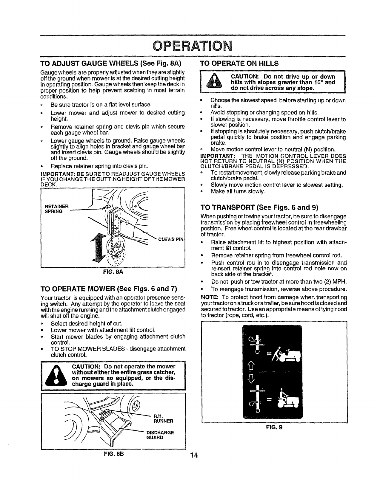
TO TRANSPORT (See Figs. 6 and 9)
When pushingortowingyourtractor, be sure to disengage
transmissionby placingfreewheel control infreewheeling
position. Free wheel control is located at the rear drawbar
oftractor.
° Raise attachment liftto highest position with attach-
ment liftcontrol.
• Remove retainer spring from freewheel control rod°
• Push control rod in to disengage transmission and
reinsert retainer spring into control rod hole now on
back side of the bracket.
• Do not pushor tow tractor at more than two (2) MPH.
° To reengage transmission, reverse above procedure,,
NOTE: To protecthood from damage when transporting
yourtractor onatruck oratrailer, be sure hoodisclosed and
secured totractor. Use an appropriate means oftying hood
to tractor (rope, cord, etc,,)o
do not drive across any slope
CAU_ON: 0o not operate the mower
without either the entire grass catcher,
on mowers so equipped, or the dis-
......... i IIIII IIII1' II ....
charge guard in place.
__"'_ R,H.
RUNNER
O,SC.ARGE
GUARD
FIG. 8B 14
FIG. 9
Page 15
OPERATION
..................................................................... illl,
BEFORE STARTING THE ENGINE
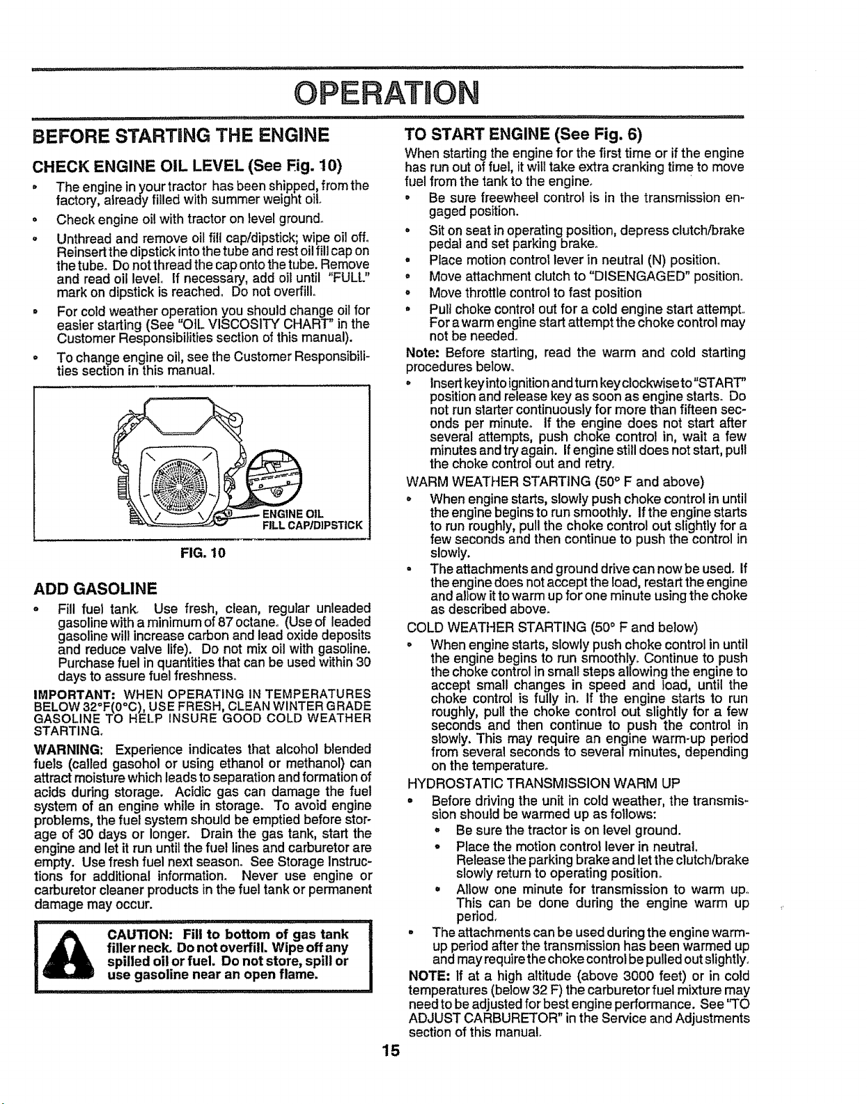
CHECK ENGINE OIL LEVEL (See Fig. 10)
o The engine inyour tractor has been shipped, fromthe
factory, already filled with summer weight oilo
• Check engine oilwith tractor on level ground°
° Unthread and remove oilfill cap/dipstick;wipe oil off°
Reinsertthe dipstickintothe tube and rest oilfill cap on
thetube° Do notthreadthecap ontothetube. Remove
and read oil level° If necessary',add oiluntil "FULL"
mark on dipstickis reached° Do not overfill,
• For cold weather operation youshould change oil for
easier starting(See "OIL VISCOSITY CHART" in the
Customer Responsibilitiessection ofthis manual).
° To change engine oil, see the Customer Responsibili-
ties section in this manual.
ENGINE OIL
FILL CAP/DIPST|CK
FIG. 10
ADD GASOLINE
o Fill fuel tank. Use fresh, clean, regular unleaded
gasolinewith a minimum of87 octane° (Use of leaded
gasolinewillincrease carbon and lead oxide deposits
and reduce valve life). Do not mix oil with gasoline.
Purchasefuel in quantitiesthatcan be usedwithin30
days to assure fuel freshness,
IMPORTANT: WHEN OPERATING IN TEMPERATURES
BELOW 32°F(0°C), USE FRESH, CLEAN WINTER GRADE
GASOLINE TO HELP INSURE GOOD COLD WEATHER
STARTING,,
WARNING: Experience indicates that alcohol blended
fuels (called gasohol or using ethanol or methanol) can
attract moisture which leads to separation and formation of
acids during storage. Acidic gas can damage the fuel
system of an engine while in storage_ To avoid engine
problems, the fuel system should be emptied before stor-
age of 30 days or longer. Drain the gas tank, start the
engine and letit run until the fuel lines and carburetorare
empty. Use fresh fuel next season. See Storage Instruc-
tions for additional tnformation. Never use engine or
carburetor cleaner products inthe fuel tank or permanent
damage may occur.
' Iq ii m q,l,,,llll,l,, I I
filler neck. Do notoverfill. Wipe off any
spilled oil or fuel. Do not store, spill or
CAUTION: Fill to bottom of gas tank
use gasoline near an open flame,
TO START ENGINE (See Fig. 6)
When starting the engine for the first time or if the engine
has run out of fuel, itwill take extra cranking time to move
fuel from the tank to the engine_
• Be sure freewheel control is in the transmission en-
gaged position.
• Sit on seat in operating position, depress clutch/brake
pedal and set parking brake°
° Place motion control lever in neutral (N) position.
° Move attachment clutch to "DISENGAGED" position,.
° Move throttle control to fast position
° Pull choke control out for a cold engine start attempt,,
For a warm enginestart attempt the choke control may
not be needed,
Note: Before starting, read the warm and cold starting
procedures below.
° Insert keyinto ignitionand turn key clockwise to"START"
position and release key as soon as enginestarts. Do
not run starter continuously for more than fifteen sec-
onds per minute° If the engine does not start after
several attempts, push choke control in, wait a few
minutes and try again. If engine still does not start, pull
the choke control out and retry_
WARM WEATHER STARTING (50° F and above)
° When engine starts, slowly push choke control in until
the enginebegins to run smoothly, if the engine starts
to run roughly, pull the choke control out slightly for a
few seconds and then continue to push the control in
slowly.
. The attachments and ground drive can now be used° If
the enginedoes not accept the load, restart the engine
and allow it to warm up for one minute using the choke
as described above.
COLD WEATHER STARTING (50° F and below)
° When engine starts, slowly push choke control in until
the engine begins to run smoothly. Continue to push
the choke control in small steps allowing the engine to
accept small changes in speed and toad, until the
choke control is fully ino If the engine starts to run
roughly, pull the choke control out slightly for a few
seconds and then continue to .push the control in
slowly. This may require an engine warm-up period
from several seconds to several minutes, depending
on the temperature°
HYDROSTATIC TRANSMISSION WARM UP
• Before driving the unit in cold weather, the transmis-
sion should be warmed up as follows:
° Be sure the tractor is on level ground.
° Place the motion control lever in neutral.
Release the parking brake and let the clutch/brake
slowly return to operating position,,
° Allow one minute for transmission to warm up.
This can be done dudng the engine warm up
period.
° The attachments can be used during the engine warm-
up period after the transmission has been warmed up
and mayrequire thechoke control be pulled out slightly.
NOTE: If at a high altitude (above 3000 feet) or in cold
temperatures (below 32 F) the carburetor fuel mixture may
need to be adjusted for best engine performance. See "TO
ADJUST CARBURETOR" inthe Service and Adjustments
section of this manual.
15
Page 16
OPERATRON
PURGE TRANSMISSION
freewheel lever while t_l_eengine is r'un-
.........................ning,.................... .................._ .......... _..... .... I
To ensure proper operation and performance, it is recom-
mended that the transmission be purged before operating
tractor for the first time. This procedure will remove any
trapped air inside the transmission which may have devel-
oped during shipping of your tractor.
IMPORTANT: SHOULD YOUR TRANSMISSION REQUIRE
REMOVAL FOR SERVICE OR REPLACEMENT, IT
SHOULD BE PURGED AFTER REINSTALLATION
BEFORE OPERATING THE TRACTOR.
o Placetractorsafely on levelsurface withengineoffand
parking brake set,.
° Disengage transmission by placing freewheel control
in freewheeling position (See "TO TRANSPORT _ in
this section of manual).
- Sitting inthetractor seat, start engine. After the engine
is running, move throttle control to slow position. With
motion control lever in neutral (N) position, slowly
disengage clutch/brake pedal
. Move motion control lever to full forward position and
hold for five (5) seconds. Move lever to full reverse
position and hold for five (5) seconds. Repeat this
procedurethree (3) times.
NOTE: During this procedure there will beno movement of
drivewheels. The air isbeing removed from hydraulic drive
system.
° Move motion control lever to neutral (N) position. Shut-
off engine and set parking brake.
° Engage transmission by placing freewheel control in
driving position (See "TOTRANSPORT" in this section
of manual).
° Sittingtn the tractor seat, startengine. Aftertheengine
is running, move throttle contro/to half (1/2) speed.
With motion control lever in neutral (N) position, slowly
disengage clutch/brake pedal°
o Slowly move motion control lever forward, after the
tractor moves approximately five (5) feet, slowly move
motion control lever to reverse position° After the
tractor moves a,pproximately five(5) feet return the
motion control tever to the neutral (N) position. Repeat
this procedure with the motion control lever three (3)
times.
• Your tractor is now purged and now ready for normal
operation,.
cAUTiON: Never engage 9r disengage I
MOWING TIPS
° Tire chains cannot be used when the mower housing is
attached to tractor°
o Mower should be properly leveled for best mowin.g
performance. See "TO LEVEL MOWER HOUSING in
the Service and Adjustments section of this manual°
° Use the runner on the right hand side of mower as a
guide. The blade cuts approximately an inch outside
the runner (See Fig° 8).
° The left hand side of mower should be used for trim-
ming.
° Drive so that clippings are discharged onto the area
that has been cut. Have the cut area to the right of the
tractor. This will result in a more even distribution of
clippings and more uniformcutting.
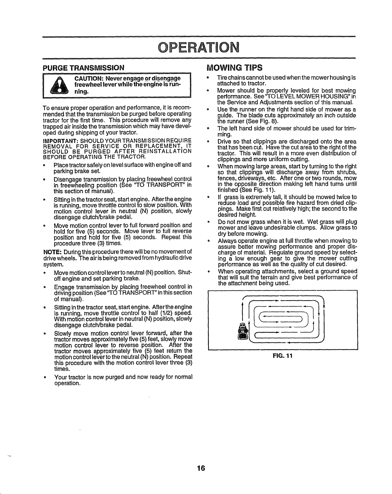
° When mowinglarge areas, startby turningtothe right
so that clippings will discharge away from shrubs,
fences, driveways, etco After one ortwo rounds, mow
in the opposite direction making left hand turns until
finished (See Fig. 1t).
= If grass is extremelytall, it should be mowed twice to
reduce load and possible fire hazard from dried clip-
pings. Make first cut relativelyhigh; the second tothe
desired height.
° Do not mow grass when it iswet Wet grass will plug
mower andleave undesirable clumps. Allow grass to
dry before mowing.
• Always operate engine at full throttlewhen mowingto
assure better mowing performance and proper dis-
charge of material. Regulate ground speed by select-
ing a low enough gear to give the mower cutting
performance as well as the quality of cut desired.
• When operating attachments, select a ground speed
that will suit the terrain and give best performance of
the attachment being used,
FIG. 11
16
Page 17
Check Brake Operation _/ _ I
Check Tire Press";e _ _#1
T
Check f0; Loose Fastener's ...... _ ................. _/7 ........ _P' ......
R Sho,pe_Rep,acoMowe,B,ades i '¢," ......." ' ".......
C Lubrication Chart ................. 1 _ _#'
T Check Battery LeveVRecharge _ ..................
0 Clean Battery and Terminals ...... _/ ............. _#_
R Check Transaxte Cooling _ .............
,Ad!u_tBladem,lt(_)Ter,sio° ..................... V'0............
Adjust Motion D_e Belt(s) Tension , , _=#'6
Check Engine 011Level if _#'
Chang;"Engin'e'"'O,.... _,_ V' ......
Clean Air Filter Vt_z
Clean Air Screen _1'2 =_=
or ..........i . ,, i[i,,,..........
I Replace Oil Biter (if equipped) _,2
NE _;_;,_;_gi,e€'0oii'n'_F_ns.................. v'_ ....
=Re;iacespar"Pl_g .... J _ ......
Replace Ai;FilterPape;' Ca'ltddge _#'2 ................. ....
Replace'Fuel Fiffer ............ I
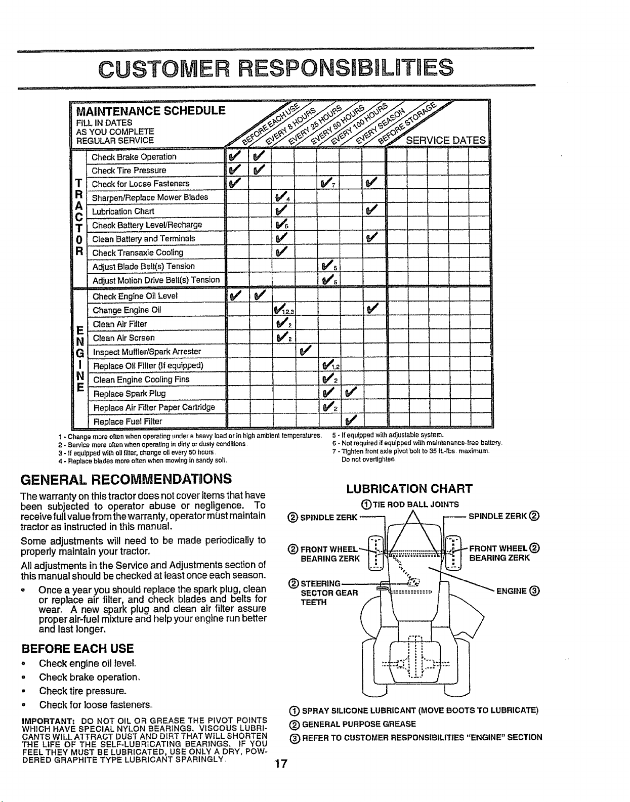
1 - Change more often when operatingunder aheavy load or in highambient temperatures,
2 - Setvlce more o{tenwhen opera[leg ]n dirty ordusty condt!lans
3 - t! equipped with oll _{ter, change olt every 50 hours.
4 - Replace blades mere often when mowing in sar_dysolt,
5- I! equippedwitha_usteblesystem..
6- Notrequiredi_equippedwithmaintenance-freebattery..
7- Tightenfrontaxlepivotboltto 35tt-tbs maximum..
Donotovertlghten
GENERAL RECOMMENDATaONS
The warrantyon thistractor does not cover itemsthat have
been subjected to operator abuse or negligence. To
receive full value from the warranty, operator mbst maintain
tractor as instructedin this manual.
Some adjustments will need to be made periodically to
properly maintain your tractor°
All adjustments in the Service and Adjustments section of
thismanual should be checked at least once each season.
= Once a year you should replace the spark plug, clean
or replace air filter, and check blades and belts for
wear. A new spark plug and clean air filter assure
proper air-fuel mixture and help your engine run better
andlast longer.
BEFORE EACH USE
. Check engine oil level,
o Check brake operation,
° Check tire pressure.
= Check for loosefasteners.
IMPORTANT: DO NOT OiL OR GREASE THE PIVOT POINTS
WHICH HAVE SPECIAL NYLON BEARINGS° VISCOUS LUBRI-
CANTS WILL ATTRACT DUST AND DIRT THAT WiLL SHORTEN
THE LIFE OF THE SELF-LUBRICATING BEARtNGS, IF YOU
FEEL THEY MUST BE LUBRICATED, USE ONLY A DRY, POW-
DERED GRAPHITE TYPE LUBRICANT SPARINGLY,
LUBRICATION CHART
(_TIE ROD BALL JOINTS
SPINDLE ZERK (_)
(_) FRONT WHEEL_
BEARING ZERK
(_ STEERING ---'-----'-'_
13_)SPRAY SILICONE LUBRICANT (MOVE BOOTS TO LUBRICATE)
(_) GENERAL PURPOSE GREASE
(E) REFER TO CUSTOMER RESPONSIBILITIES "ENGINE" SECTION
BEARING ZERK
ENGINE (_)
17
E)
Page 18
TRACTOR
Always observe safety rules when performing any mainte-
nance.
BRAKE OPERATION
If tractor requires more than six (6) feet stopping distance
at high speed inhighest gear, then brake must be adjusted°
(See "TO ADJUST BRAKE" in the Service and Adjust-
ments section of this manual).
TIRES
• Keep tires free of gasoline, oil, or insect control chemi-
cals which can harm rubber.
° Avoid stumps, stones, deep ruts, sharp objects and
other hazards that may cause tire damage,
NOTE: To seal tire punctures and prevent flat tires due to
slow leaks, tire sealant may be purchased from your local
parts dealer. Tire sealant also prevents tire dry rot and
corrosion.
BLADE CARE
For best results mower blades must be kept sharp. Re-
place bent or damaged blades°
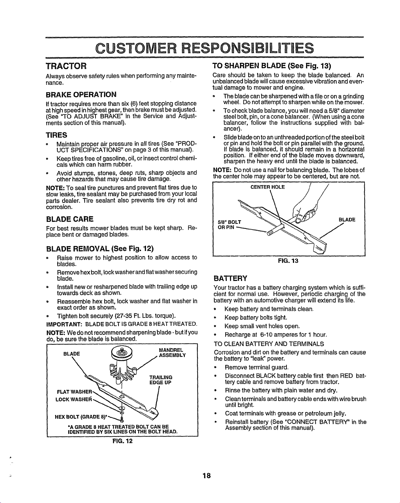
TO SHARPEN BLADE (See Fig. 13)
Care should be taken to keep the blade balanced. An
unbalancedblade willcauseexcessive vibrationand even-
tual damage to mower and engine_
The bladecan be sharpened witha fileor on a grinding
wheel, Do not attemptto sharpen while on the mower°
° To checkblade balance,you will needa 5/8" diameter
steelbolt,pin,or acone balancer,, (When usinga cone
batancer, follow the instructions supplied with bal-
ancer).
° Slide b_adeonto an unthreaded portion of the steel bolt
or pin and holdthe bolt or pinparallel with the ground.
If blade is balanced, it should remain in a horizontal
position. If eitherend of the blade moves downward,
sharpen the heavy end untilthe blade is balanced.
NOTE: Do not use anail for balancing blade. The lobes of
the center hole may appear to be centered, but are not.
BLADE REMOVAL (See Fig. 12)
° Raise mower to highest position to allow access to
blades°
° Remove hex bolt, lock washer and flat washer securing
blade.
= Install new or resharpened blade with trailing edge up
towards deck as shown.
• Reassemble hex bolt, lock washer and flat washer in
exact order as shown.
° Tighten bolt securely (27-35 Ft. Lbs. torque).
IMPORTANT: BLADEBOLTtSGRADE 8 HEATTREATEDo
NOTE: We donot recommend sharpening blade -butifyou
do, be sure the blade is balanced.
BLADE ASSEMBLY'
FLAT _,= /
WAS
HEX BOLT (GRADE 8)*
•A GRADE 8 HEAT TREATED BOLT CAN BE
IDENTIRED BY SIX LINES ON THE BOLT HEAD,
FIG. 12
MANDREL
TRAILING
EDGE UP
FIG. 13
BATrERY
Your tractor has a batter;/charging system which is suffi-
cient for normal use. However, periodic charging of the
battery with an automotivecharger will extend itslifeo
- Keep batteryand terminals clean.
= Keep batter'), bolts tight.
o Keep small vent holes open.
° Recharge at 6-10 amperes for 1 hour.
TO CLEAN BATTERY AND TERMINALS
Corrosionand dirt on the battery and terminals can cause
the battery to "leak" power.
• Remove terminal guard,
° Disconnect BLACK battery cable first then RED bat-,
tery cable and remove battery from tractor.
° Rinse the battery withplain water and dry.
° Clean terminalsand batterycable endswithwire brush
until bright.
° Coat terminals with grease or petroleum jelly.
= Reinstal_ batterY (See "CONNECT BATTERY" in the
Assembly section of this manual)°
_ 18
Page 19

CUSTOMER R
_;,,;,,....... 1,;....... :........ i iiH,, i, i,,
TRANSAXLE COOLING
The fan and cooling fins of transmission should be kept
clean to assure proper cooling..
Do not attempt toclean fan or transmission while engineis
running or while the transmission is hot. To prevent
possible damage to seals, no not use high pressure water
or steam to clean transaxle_
, Inspect cooling fan to besure fan blades are intact and
clean_
° Inspect cooling fins for dirt, grass clippings and other
materials° To prevent damage to seals, do not use
compressed air or high pressure sprayer..
TRANSAXLE PUMP FLUID
The transaxle was sealed at the factor.7and fluid mainte_
nance is not required for the life of the transaxle. Should
the transaxte ever leak or require servicing, contact your
nearest authorized service centeddepartment,
V-BELTS
CheckV-belts for deteriorationand wear after 100 hours of
operation and replace if necessary. The belts are not
adjustable. Replace belts ifthey begin to slip from wear°
BILITIES
TO CHANGE ENGINE OIL (See Figs, 14 and I5)
Determine temperature range expected before oil change.
All oil must meet API service classification SF, SG or SH.
• Be sure tractor is on level surface.
. Oil will drain more freely when warm,
. Catch oil in a suitable container.
° Remove oitfill cap!dipstick. Be careful not to allow dirt
to enter the engine when changing oit,
• Remove drain plug.
. After oil has drained completely, replace oil drain plug
and tighten securely
. Refill engine with oilthrough oil fill dipstick tube. Pour
slowly. Do not overfill For approximate capacity see
PRODUCT SPECIFICATIONS on page 3 of this
manual.
, Usegauge on oil fill cap/dipstick for checking level. Be
sure dipstick is in, all the way for accurate reading.
Keep oil at FULL line on dipstick.
AIR SCREEN OIL DRAIN PLUG
ENGINE
LUBRICATION
Only use high quality detergent oil rated withAPI service
classification SF, SG or SHo Select the oil's SAE viscosity
grade according to your expected operating temperature.
SAE VISCOSFI'Y GRADES
....
_F ,, "2D'_ O° "' 30;"" 32 ° 40 = 60 ° BB' '" 10_;'"
°€ ._o. ._. ._o o_ lo" ,;o" 3_ ,'0o
TEMPERATURE RANGE ANTICIPATED'BEFORE N_ OLL CHANGE
FIG. 14
Change the oi!after every 50 hours of operation or at least
once ayear ifthe tractor is not usedfor 50 hours inone year.
Check the crankcase oil level before starting the engine
and after each eight (8) hours of operation. Tighten oil fill
cap/dipsticksecurely each time you check the oil level.
ENGINE OIL
FILL CAP/DIPSTICK
FIG. 15
CLEAN AIR SCREEN (See Fig. 15)
Air screen must be kept free of dirt and chaff to prevent
engine damage from overheating, Clean with a wire brush
or compressedair to remove dirtand stubborn dried gum
fibers.
19
Page 20

CUSTOMER
' " :::: = : : :: .....;
CLEAN AIR INTAKF_-JCOOLING AREAS
To insure proper cooling, make sure the grass screen,
cooling fins, and other external surfaces of the engine are
kept clean at all times.
Every 100 hours of operation (more often under extremely
dusty, dirty conditions), remove the blower housing and
other cooling shrouds. Clean the cooling fins and external
surfaces as necessary° Make sure the cooling shrouds are
reinstalled.
NOTE: Operating the engine with a blocked grass screen,
dirb] or plugged cooling fins, and/or cooling shrouds re-
moved will cause engine damage due to overheating,.
AIR FILTER (See Fig. 16)
Your engine will not run properly using a dirty,air filter.
Clean the foam pre-cleaner after every 25 hoursof opera-
tion or every season. Service paper cartridge every 100
hours of operation or every season, whichever occurs first.
Service air cleaner more often under dusty conditions.
, Loosen knob and remove cover..
TO SERVICE PRE-CLEANER
° Slide foam pre-cleaner off cartridge.
° Wash it in liquid detergent and water.
= Squeeze it dr,] in a clean cloth.. Allow it to dry.
* Saturate it in engine oil,. Wrap it in clean, absorbent
cloth and squeeze to remove excess oil
TO SERVICE CARTRIDGE
° Replace a dirty, bent, or damaged cartridge.
NOTE: Do notwash the paper cartridge or usepressurized
air, as this will damage the cartridge.
, Remove nut and cartridge plate.
= Reinstall the pre-cleaner (cleaned and oiled) over the
paper cartridge.
o Check rubber seal for damage and proper position
around stud. Replace if necessary.
o Reassemble air cleaner, cartridge plate, and nut.
° Reinstall air cleaner cover and secure by tightening
knob.
CARTRIDGE
FOAM
PRE_;LEANER
CAR'[RIDGE
PLATE
\
RUBBER
SEAL
LITllES
ENGINE OIL FILTER
Replace the engineoilfilter every season or everyotheroil
change ifthe tractor is used more than 100 hours in one
year.
MUFFLER
Inspect and replacecorroded muffler and spark arrester (if
equipped)as itcouldcreate a firehazard and/or damage.
SPARK PLUGS
Replace spark plugs at the beginning of each mowing
season or after every 100 hours of operation, whichever
occursfirst. Spark plugtype and gap setting are shown in
"PRODUCT SPECIFICATIONS" onpage 3 of this manual.
IN-LINE FUEL FILTER (See Fig. 17)
The fuel filter should be replacedonceeach season° If fuel
fitter becomes clogged,obstructingfuel flow to carburetor,
replacement is required,
° With engine coot,
sections.
Place new fuel filter in positionin fuel line with arrow
pointing towards carburetor_
Be sure there are no fuel line leaks and clamps are
properlypositioned.
Immediately wipe up any spilled gasoline°
CLAM| FUEL RLTER
CLEANING
= Clean engine, battery, seat, finish, etCoof all foreign
matter.
• Keep finished surfaces and wheels free of all gasoline,
oil, etc.
° Protect painted surfaces with automotive type wax.
We do not recommend using a garden hose to clean your
tractor unless the electrical system, muffler, air filter and
carburetor are covered to keep water out. Water in engine
can result in a shortened engine life.
remove filter and plug fuel line
CLAMP
FIG. 17
NUT
FIG. 16
20
Page 21

$ERVmCEA ADJU
,, - ,....... .............. ,,,
CAUTION; BEFORE PERFORMING ANY SERVICE OR ADJUSTMENTS;
• Depress clutch/brake pedal fully and set parking brake.
Place attachment clutch in "DISENGAGED" position.
o
= Place motion control lever in neutral (N) position.
Turn ignition key "OFF" and remove key.
o
Make sure the blades and all moving parts
o
Disconnect spark plug wire from spark plug
plug.
have completely stopped.
and place wire where itcannot come in contact with
TRACTOR
TO REMOVE MOWER (See Fig. 18)
• Placeattachment clutch in "DISENGAGED" position°
o Turn height adjustment knob to lowest setting,
• Lower mower to its lowest position.
o Remove retainer spring holding anti-swaybar to chas-
sis bracket and disengage anti-swaybar from bracket.
o Remove retainer springs from suspension arms at
deck and disengage arms from deck.
° Raise attachment lift to its highest position_
° Remove two retainer springs from each front link and
remove links.
o Slide mower forward and remove belt from electdc
clutch pulley°
o Slide mower out from under right side of tractor.
IMPORTANT; IF AN ATTACHMENT OTHER THAN THE
MOWER DECK IS TO BE MOUNTED ON THE TRACTOR,
REMOVE THE FRONT LINKS
TO iNSTALL MOWER
Follow procedure described in "INSTALL MOWER AND
DRIVE BELT" in the Assembly section ofthis manual
FRONT
SUSPENSION
BRACKET,
BRACKET
SUSPENSION
ARMS ADJUSTMENT
CHASSIS
NUTS
LIFT
LINKS
TO LEVEL MOWER HOUSING
Adjust the mower whiletractor is parked on level ground or
driveway. Make sure tires are propedy inflated (See
"PRODUCT SPECIFICATIONS" on page 3of this manual),
Iftires are over or underinflated, you will not proper)y adjust
your mower°
SIDE-TO-SIDE ADJUSTMENT (See Figs. 18 and 19)
° Raise mower to its highest position°
° Measure height from bottom of deck curl to ground
level at front corners of mower. Distance "A" on both
sides of mower should be the same.
°
If adjustment is necessary, make adjustment on one
side of mower onlyo
o
To raise one side of mower, tighten liftlink adjustment
nut on that side.
°
To lower one side of mower, loosen lift link adjustment
nut on that sider
NOTE: Each halfturn ofadjustment nutwill change mower
height about 3/16".
° Recheck measurements after adjusting.
BOTTOM BOTTOM
OF CURL OF CURL
FIG. 19
ELECTRIC
CLUTCH
PULLEY
FRONT
SUSPENSION
BRACKET
RETAINER
SPRING
ANTI-SWAY RETAINER
BAR SPRINGS
RETAINER
.FRONT MOWER
BRACKET
FIG. 18
21
Page 22

SERVICE AND ADJUSTr IENTS
FRONT-TO-BACK ADJUSTMENT (See Figs° 20 and 21)-
IMPORTANT; DECK MUST BELEVEL SIDE-TO-SIDE, tF
THE FOLLOWING FRONT-TO-BACK ADJUSTMENT IS
NECESSARY, BESURE TO ADJUSTBOTH FRONT LINKS
EQUALLY SO MOWER WILLSTAY LEVEL SIDE-TO-SIDE,
To obtain the best cutting results, the mower housing
should be adjusted sothe front isapproximately 1/8"to 1/2"
lower than the rear when the mower is in its highest
position°
Check adjustment on right side oftractor. Measure dis-
tance "F" directly in front of and behind the mandrel at
bottom edge of mower housing as shown.
° Before making any necessary adjustments, checkthat
both front links are equal in length_
° If linksare not equal in length, adjust one link to same
length as other link.
° To !owerfrontofmowerhousing, loosen nut"G" on both
front links an equal numberof turns°
o When distance "F" is 1/8" to 1/2" lower at front than
rear,tightennut"H"against trunniononboth front links°
o To raise front of mower housing,loosen nut "H" from
trunnion on both front links. Tighten nut"G" on both
front linksan equal number of turns°
° When distance "F" is 1/8" to 1/2" Dowerat front than
rear, tighten nut "H" against trunnion on both front
links.
NOTE: Each full turn of nut "G" will change dim, "F" by
approximately 3/8",
o Recheck side-to-side adjustment.,
MANDREL
....... ..../,,jllllllll.............. ............ , ,,=1,,,.i , i,
TO REPLACE MOWER DRIVE BELT
MOWER DRIVE BELT REMOVAL (See Fig. 22) -
° Park tractor on a level surface. Engage parking brake.
° Remove four screws from L.H, mandrel cover and
remove cover.
° Roll belt over the top of L.Homandrel pulley.
= Remove beltfrom electric clutch pulley.
o Remove beltfrom idler pulleys.
= Remove any dirt or grass clippings which may have
accumulatedaround mandrels and entire upper deck
surface.
o Checkprimarj idler arm and two idlers to see that they
rotate freely,
o Be sure spring is securely hooked to primary idlerarm
and bolt in mower housing_
MOWER DRIVE BELT INSTALLATION (See Fig. 22) -
• Install belt in both idlers. Make sure belt is in both belt
keepers at the idlersas shown°
o Install new belt onto electric clutch pulley.
° Roll belt into upper groove of L,H, mandrel putley.
o Carefully check belt routing making sure belt is in the
grooves correctly and inside belt keepers,
• Reassemble L,H_mandrel cover,
LH. SCREWS ELECTRIC
MANDREL SPRING CLUTCH
COVER IDLER PULLEY
PULLEYS
PRIMARY
IDLER
ARM
FIG. 20
BOTH FRONTLINKS SHOULDBEEQUALIN LENGTH
NUT"H"
FRONT LINKS
FIG. 21 22
MANDREL
MOWER
DRIVE BELT
BOLTIN
MOWER
HOUSING
BELT
KEEPER
FIG. 22
Page 23

ERVBCE AND ADJUSTMENTS
TO REPLACE MOWER BLADE DRIVE BELT
(See Fig. 23)
Park the tractor on level surfacer Engage parking braker
. Remove mowerdrive belt (See"TO REPLACE MOWER
DRIVE BELT" in this section of this manual)°
. Remove mower (See "TO REMOVE MOWER" in this
section of this manual),
° Remove four screws from R_H.,mandrel cover and
remove cover° Unhook spring from bolt on mower
housing.
° Carefully roll belt off RoH_mandrel pultey_
= Remove belt from center mandrel pulley, idlerpulley,
and L.H. mandrel pulley.
= Remove any dirt or grass which may have accumu-
lated around mandrels and entire upper deck surface°
= Check secondary idler arm and idler to see that they
rotate freely.
° Be sure spring is hooked in secondary idler arm and
sway-bar bracket°
° Install new belt inlower groove of Loll. mandrel pulley,
idler pulley, and center mandrel pulley as shown.
° Roll belt over R.Homandrel pulley, Make sure belt isin
all grooves properly.
° Reconnect spring to bolt in mower housing and rein-
stall RHo mandrel cover.
° Reinstall mower to tractor (See "INSTALL MOWER
AND DRIVE BELT" in the Assembly section of this
manual).
° Reassemble mower drive belt (See "TO REPLACE
MOWER DRIVE BELT" in this section of this manual).
L.H. MOWER BLADE
DRIVE BELT CENTER
MANDREL
MANDREL
COVER
SECONDARY
IDLER ARM
NOTE: After installing a new electric clutch, run tractor at
full throttle and engage and disengage electric clutch 10
cycles to wear in clutch plate.
NYLON LOCKNUT (3)
BRAKE PLATE
FIG. 24
TO ADJUST BRAKE (See Fig. 25)
Your tractor is equipped with an adjustable brake system
which is mounted on the side of the transaxle.
If tractor requires more than six (6) feet stopping distance
at high speed in highest gear, then brake must beadjusted°
° DepressclutchrDrake pedal and engage parking brake,
° Measure distance between brake operating arm and
nut "A" on brake rod°
Ifdistance isother than 1-1/2", loosen jam nut and turn
nut "A" until distance becomes 1-1/2". Retighten jam
nut against nut "A",
Roadtest tractor for proper stopping distance asstated
above. Readjust if necessary. If stopping distance is
still greater than six (6) feet in highest gear, further
maintenance is necessary. Contact your nearest au-
thorized service centeddepartment.
WITH PARKING BRAKE "ENGAGED"
NLTT"A"
JAM NUT
SWAY*BAR IDLER
BRACKET PULLEY
RG. 23
TO ADJUST ATTACHMENT CLUTCH
(See Fig. 24)
The electric clutchshould provide years of service° The
clutch has a built-in brake that stops the pulley within 5
seconds. Eventually, the internal brake will wear which
may cause the mower blades to not engage, or, to not stop
as required,. Adjustments should bemade by your nearest
authorized service center/department,
. Make sure attachment clutch and ignition switches are
in "OFF" position.
° Adjust the three nylon Iocknuts until space between
clutch plate and rotor measures .0t2" at all three slot
locations cut in side of brake plate.
OPERATING
ARM
FIG. 25
23
Page 24

RVDCEA
I_. ._ ,, .H IIIL"II , " 'I'IIMI' ,.......
TO REPLACE MOTION DRIVE BELT
(See Fig. 26)
Park the tractor on level surface. Engage parking brake.
Forease of service there is abelt installation guide decal on
bottom of left footrest.
o Remove mower (See 'q'O REMOVE MOWER" in this
section of this manual,.)
BELT REMOVAL-
• Engage parking brake (creates slack in belt)o
° Remove belt from clutching and fan idlerpulleys°
o Loosen belt keeper above transaxle pulley.
, Remove belt from transaxle pulley.
° Remove belt from engine pulley and front V-idler pul-
ley.
° Pull belt out of allbelt keepers and remove from tractor.
BELT INSTALLATION -
o Place V part of belt into grooves on engine pulley and
front Voidler, making sure to route belt inside of all belt
keepers°
° Route belt on right side, coming from V-idler, towards
back of tractor, above midspan belt keeper and to top
of transaxle pu|ley.
° Route belt on left side, coming from engine pulley,
towards back of tractor and through loop in mldspan
belt keeper.
• Place V part of belt into grooves on transaxle and fan
idlerpulleys, making sure to route belt inside of all belt
keepers.
o Retighten belt keeper above transaxle pulley°
° Place belt around clutching idlers as shown, making
sure to route belt inside of all belt keepers.
. Check to be sure belt is positioned correctly and is on
proper side of all belt keepers.
, Reinstall mower.
IMPORTANT: CHECK BRAKE ADJUSTMENT.
TRACTORV-BELT DRIVESCHEMATIC
VIEWED FROM LH. SIDE OFTRACTOR
CLUTCHING TRANSAXLE
BELT PULLEY
KEEPER
ENGINE
PULLEY
V_IDLER KEEP!
ADJUSTMENTS
TO ADJUST MOTION CONTROL LEVER
(See Fig. 27)
The motioncontrolleverhas been preset at thefactory and
adjustment should not be necessary,.
If for any reason the motion control lever wil! not hold its
positionwhile at a selected speed, it may be adjusted at the
friction pack located on the right side of chassis.
o Park tractor on level surface° Stop tractor by turning
ignition key to OFF" position and engage parking
brake.
° Place motion control lever in neutral (N) position.
° While holding locknut, loosen jam nut
= Tighten Iocknut 1/4 tum.
° While holding Iocknut, tighten jam nut securely.
NOTE: If for any reason the effort to move the motion
control lever becomes too excessive, reverse the above
adjustment procedure by loosening locknut 1/4 turn.
Road test tractor after adjustment and repeat procedure if
necessary.
LOCKNUT
JAM NUT
FIG. 27
TRANSMISSION REMOVAL/REPLACEMENT
Should your transmission require removal for service or
replacement, it should be purged after reinstallation before
operating the tractor. See "PURGE TRANSMISSION" in
Operation section of this manual.
BE_
KEEPER BELT
ASVIEWED FROM BOTTOM
FIG. 26
TWISTS
BELT FAN
KEEPER ID_R
TO ADJUST STEERING WHEEL ALIGNMENT
Ifsteering wheel crossbars are not horizontal (left to fight)
when wheels are positioned straightforward, remove steer-
ingwheel and reassemble per instructions in the Assembly
section of this manual.
24
Page 25

SERVnCE AND ADJUSTMENTS
FRONT WHEEL TOE-IN ADJUSTMENT
Front wheel toe-in is required forproper steering operation°
Toe-in was set at the factory and adjustment should not be
necessary° Ifparts in the front axle or steedng mechanism
have been replaced or damaged, check toe-in and adjust
if necessary.
TO CHECK TOE-IN (See Fig°28) -
° Position front wheels straight ahead.
o Measure distance between wheels at front and rear of
tires (dimensions"A" and "B").
= Front dimension "A" should be 1/8" to 1/4" less than
rear dimension "B".
TO ADJUST TOE-iN (See Figs. 28 and 29) -
. Loosen jam nuts at adjustment sleeves on tie rod.
° Adjust tie rod until dimension"A" is1/8" to 1/4"less than
dimension "B°,,
= Tighten jam nuts securely.
FIG. 28
ADJUSTMENT
SLEEVES
JAM
TIE ROD
FIG. 29
FRONT WHEEL CAMBER
The front wheel camber is notadjustable onyour tractoro If
damage has occurred to affect the front wheel camber,
contact your nearest authorized service center/depart-
ment
WAS1
RETAINING
RING
AXLE
COVER
FIG. 30
NOTE: To seal tire punctures and prevent flat tires due to
slow leaks, tire sealant may be purchased from your local
parts dealer. Tire sealant also prevents tire dry rot and
corrosion.
TO START ENGINE WITH A WEAK BATTERY
(See Fig. 31)
:: i ,_,'_ : .......... ,. ,,,,,,,,i.....
CAUTION: Lead-acid batteries gener-
ateexplosive gases. Keepsparks, fiame
and smoking materials away from bat-
teries. Always wear eye protection
when around batteries.
tf your battery is too weak to start the engine, it should be
recharged. If "jumper cables" are used for emergency
starting, foltow this procedure:
IMPORTANT: YOUR TRACTOR IS EQUIPPED WITH A 12
VOLT NEGATIVE GROUNDED SYSTEM,, THE OTHER
VEHICLE MUST ALSO BE A 12 VOLT NEGATIVE
GROUNDED SYSTEM. DO NOT USE YOUR TRACTOR
BATTERY TO START OTHER VEHICLES,,
TO ATTACH ,JUMPER CABLES -
° Connect each end of the RED cable to the POSITIVE
(+) terminal of each battery, taking care not to short
against chassis.
- Connect one end of the BLACK cable to the NEGA-
TIVE (-) terminal of fully charged battery°
• Connect the other end of the BLACK cable to good
CHASSIS GROUND, away from fuel tank and battery.
TO REMOVE CABLES, REVERSE ORDER -
• BLACK cable first from chassis and then from the fully
charged battery.
- RED cable last from both batteries°
TO REMOVE WHEEL FOR REPAIRS
FRONT WHEEL (See Fig, 30) -
° Block up axle securely.
• Remove axle cover,retaining ringandwashersto allow
wheel removal.
° Repair tire and reassemble.
- Replace washers and snap retaining ringsecurely in
axle groove.
° Replace axle cover,
REAR WHEEL -
° Block rear axle securely.
° Remove five (5) hub bolts to allow wheel removal
° Repair tire and reassemble. Replace and tightenhub
bolts securely.
25
"POSITIVE" (+)
"NEGATIVE" (_)
LH° PANEL l_ /
FIG. 31
Page 26

ERVmCEA
A USTMENTS
TO REPLACE HEADLIGHT BULB
• Raise hood_
• Pull bulb holder out of the hole in the backside of the
grill.
o Replace bulb in holder and push bulb holder securely
back intothe hole in the backside of the grill,
° Close hood.
INTERLOCKS AND RELAYS
Loose or damaged wiring may cause your tractor to run
poody, stop running, or prevent it from starting.
, Check wiring. See electrical wiring diagram in the
Repair Parts section of this manual
TO REPLACE FUSE
Replace with 30 amp automotive-type plug-in fuse. The
fuse holder is located behind the dash.
TO ADJUST ATTACHMENT LIFT SPRING
(See Fig. 32)
- While bottlingspdng bushing withwrench, loosen jam
nut°
• Turn adjustment bolt clockwise to extend spring and
reduce lift effortfor heavier attachments
o Turn adjustment bolt counterclockwisefor lighter at-
tachments.
° Retighten jam nut against spring bushing.
IMPORTANT; DO NOT ADJUST FOR MAXIMUM SPRING
TENSION WHEN USING LIGHT ATTACHMENTS SUCH
AS A MOWER° ADJUST LIFT LEVER SPRING TO AID IN
LIFTING ATTACHMENT. DO NOTOVERPOWER SPRING.
WHEN REMOVING ATTACHMENT, ALWAYS ADJUST
SPRING TENSION TO ITS LOWEST POSITION°
TO REMOVE HOOD AND GRILL ASSEMBLY
(See Fig. 33)
. Raise hood.
= Unsnap headlight wire connector,,
° Stand infront oftractor. Grasp hood atsides, tilt toward
engine and lift off of tractor.
o To replace, reverse above procedures.
HEADLIGHT
WiRE
CONNECTOR
HOOD
FIG. 33
ENGINE
ADJUSTMENT SPRING BUSHING
BOLT
¢ ATTACHMENT
JAM NUT LIFT SPRING
FIG. 32
TO ADJUST THROTTLE CONTROL CABLE
(See Fig. 34)
The throttle control has been preset at the factory and
adjustmentshould not be necessary. Check adjustment as
described below before loosening cable. If adjustment is
necessary, proceed as follows:
= With engine not running, move throttle control lever to
fast position°
° Check that speed control lever is against stop screw. If
it is not, loosen casing clamp screw and pull throttle
cable until lever is against screw. Tighten clamp screw
securely,
26
Page 27

SE VMCEAND AD, USTMENTS
IDLE FUEL
ADJUSTING IDLE SPEED
NEEDLE
THROTTLE
CONTROL
CABLE
3HOKE
CONTROL
CABLE
STOP
SCREW P
SCREW
FIG. 34
TO ADJUST CHOKE CONTROL
(See Figs. 34 and 35)
The choke control has been preset at the factory and
adjustment should not be necessary_ check adjustment as
described below before loosening cable,, If adjustment is
necessary, proceed as follows:
= With engine not running, move choke control (located
on dash panel) to full choke position.
* Remove air cleaner cover, filter and cartridge plate to
expose carburetor choke (See "AIR FILTER" in the
Customer Responsibilities section of this manual)°
. Choke should be closed° if it is not, loosen casing
clamp screw and move choke cable until choke is
completely closed° Tighten casing clamp screw se-
curely.
. Reassemble air cleaner.
FULLCHOKE
CLOSED FOR_
TO ADJUST CARBURETOR (See Fig, 34)
The carburetorhasbeen present at thefactory and adjust-
ment should not be necessary. However, minoradjustment
may be required to compensate for differences in fuel,
temperature, altitude or load. If the carburetordoes need
adjustment,proceed as follows:
In general, turning the adjusting needles in (c_ockwise)
decreases the supply of fuel to the enginegiving a leaner
fuel/air mixture° Turning the adjusting needles out (coun-
terclockwise) increases the supply of fuel to the engine
giving a richer fuel/air mixture,
IMPORTANT: DAMAGE TO THE NEEDLES AND THE
SEATS IN CARBURETOR MAY RESULT IF SCREW IS
TURNED IN TOO TIGHT°
PRELIMINARY SETTING -
° Be sure you have a clean air filter, and the throttle
control cable is adjusted proper!y (see "TO ADJLIST
THROTTLE CONTROL CABLE in the Service and
Adjustments section of this manual).
• With engine off turn idle fuel adjusting needle in (clock-
wise) closing it finger tight and then turn out (counter-
clockwise) 1 turn,,
FINAL SETTING -
= Start engine and allow to warm for five minutes° Make
final adjustments with engine running and shifVmotion
control lever in neutral (N) position.
° The high idle is set at the factory and cannot be
adjusted,,
o L_,lespeed,se,_inq - With throttle controllever in slow
position, engine should idle at 'i200 RPMo If engine
Idlestoo slow orfast, turn idle speed adjusting screw in
or out until correct idle is attained.
. Idle fuel needle settina - With throttle control lever in
slowposition, turn idie fuel adjusting needfe in (clock-
wise) until engine speed decreases and then turn out
(counterctocl_wise) approximately 3/4turn to obtain the
best low speed performance.
° Recheck idle speed_ Readjust if necessary,
ACCELERAt"ION TEST -
• Move throttle control lever from slow to fast position.If
engine hesitates or dies, tum idle fuel adjusting needle
out (counterclockwise) 1/8 turn. Repeat test and con-
tinue to adjust, if necessary, until engine accelerates
smoothly°
High speed stop isfactory adjusted_ Do not adjust-damage
may result.
IMPORTANT: NEVER TAMPER WITH THE ENGINE
GOVERNOR, WHICH IS FACTORY SET FOR PROPER
ENGINE SPEED, OVERSPEEDtNGTHE ENGINE ABOVE
THE FACTORY HIGH SPEED SETTING CAN BE
DANGEROUS. IF YOU THINKTHE ENGINE-GOVERNED
HIGH SPEED NEEDS ADJUSTING, CONTACT YOUR
NEAREST AUTHORIZED SERVICE CENTER/
DEPARTMENT, WHICH HAS PROPER EQUIPMENT AND
EXPERIENCE TO MAKE ANY NECESSARY
ADJUSTMENTS°
FIG. 35
27
Page 28

STORAGE
Immediately prepare your tractor for storage at the end of
the season or if the tractor will not be used for 30 days or
_ore.
_, CAUTION: Never store the tractor with
A JL gasoline in the tank inside a building |
where fumes may reach an open flame I
or spark,. Allow the engine to cool i
before storing in any enclosure.
TRACTOR
Remove mower from tractor for winter storage,, When
mower is to be stored for a period of time, clean it thor-
oughly, remove all dirt, grease, leaves, etc,. Store in a
clean, dry area.
• Clean entire tractor (See"CLEANING" inthe Customer
Responsibilities section of this manual)°
• Inspect and replace belts, if necessary (See belt re-
placement instructions inthe Service and Adjustments
section of this manual).
o
Lubricate as shown in the Customer Responsibilities
section of this manual.
o
Be sure that all nuts, bolts and screws are securely
fastened. Inspect moving parts for damage, breakage
and wear. Replace if necessary.
Touch up all rusted or chipped paint surfaces; sand
lightly before painting.
BATTERY
• Fully charge the battery for storage°
o After a periodof time in storage, battery may require
recharging°
° To help prevent corrosion and power leakage during
long periods of storage, battery cables should be
disconnected and battery cleaned thoroughly (see "TO
CLEAN BATTERY AND TERMINALS in the Cus-
tomer Responsibilities section of this manual).
° After cleaning, leave cables disconnected and place
cables where they cannot come in contact with battery
terminals°
° Be sure battery drain tube is securely attached.
° if battery is removed from tractor for storage, do not
store battery directly on concrete or damp surfaces.
ENGINE
FUEL SYSTEM
IMPORTANT: tT IS IMPORTANT TO PREVENT GUM
DEPOSITS FROM FORMING IN ESSENTIAL FUEL
SYSTEM PARTS SUCH AS CARBURETOR, FUEL FILTER,
FUEL HOSE, OR TANK DURING STORAGE, ALSO,
EXPERIENCE INDICATES THAT ALCOHOL BLENDED
FUELS (CALLED GASOHOL OR USING ETHANOL OR
METHANOL) CAN ATTRACT MOISTURE WHICH LEADS
TO SEPARATION AND FORMATION OF ACIDS DURING
STORAGE. ACIDIC GAS CAN DAMAGE THE FUEL
SYSTEM OF AN ENGINE WHILE IN STORAGE_
° Drain the fuel tank,
o Start the engine and let it run until the fuel lines and
carburetor are empty.
° Never useengine orcarburetor cleaner products inthe
fuel tank or permanent damage may occur.
. Use fresh fuel next season.
NOTE: Fuel stabilizer is an acceptable alternative in
minimizingthe formation of fuel gum deposits during stor-
age. Add stabilizer to gasoline in fuel tank or storage
container. Atways follow the mix ratio found on stabilizer
container. Run engine at least 10 minutes after adding
stabilizertoallowthe stabilizer to reach thecarburetor. Do
not drain thegas tank and carburetor ifusing fuet stabilizer.
ENGINE OIL
Drain oil (withengine warm) and replace withclean engine
oil (See "ENGINE" in the Customer Responsibilities
section of this manual).
CYLINDERS
° Remove spark ptug(s)_
• Pour one ounce of oil through spark plug hole(s) into
cytinder(s) o
° Turn ignition key to "START" position for a few seconds
to distribute oil.
° Replace with new spark plug(s).
OTHER
° Do not store gasoline from one season to another_
° Reptace your gasoline can if your can starts to rust.
Rust and/or dirt inyour gasoline willcause problems.
° ff possible, storeyour tractor indoors and cover it to
give protectionfrom dust and dirt.
° Cover yourtractorwitha suitable protectivecover that
does not retain moisture. Do not use plastic. Plastic
cannotbreathewhichallowscondensation to form and
willcause yourtractorto rust°
IMPORTANT: NEVER COVERTRACTOR WHILE ENGINE
AND EXHAUST AREAS ARE STILL WARM..
28
Page 29

PROBLEM
CAUSE
CORRECTION
Will not start
Hard to start
Engine will not turn over
1.. Out of fuel
2. Engine not "CHOKED" properly.
3. Engine flooded,,
4, Bad spark plug
5. Dirty air filter,
6,, Dirty rue! filter..
7. Water in fuel
8, Loose or damaged wiring,
9 Carburetor out of adjustment.
10o Engine vatves out of adjustment,
1, Dirty air filter.
2. Bad spark plug,
3o Weak or dead battery.,
4_ Dirty fuel filtsro
5. Stale or dirty fuel
6. Loose or damaged wiring.,
7, Carburetor out of adjustment,
8o Engine valves out ofadjustment
1_ Clutch!brake pedal not depressed,.
2o Attachment clutchis engaged,
3, Weak or dead battery..
4o Blown fuse,
5- Corroded battery terminals,
6, Loose or damaged wiring_
7., Faulty ignitionswitch.
8, Faulty solanaid or starter.,
9. Faulty operator presence swttch(es)_
1, Fiil fuel tank,
2. See "TO START ENGINE" in Operation section_
3, Watt several minutes before attempting to start
4_ Replace spark plug,
5 Clear_repface air filter.
6_ Replace fuel filter,,
7, Drain fuel tank and carburetor, refill tank wffh fresh
gasoline and replace fuel fitter,
81 Check alewiring.
9 Sea"To Adjust Carburetor" in Service Adjustments
section,,
10o Contact an authorized service center/department,
11 Clean/repIace air filter,
2, Replace spark plug,,
3 Recharge or replace battery,
4, Reptace fuel fittero
5o Drain fuel tank and refill with fresh gasoline,
6. Check all wiring.
7. See "To Adjust Carburetor" in Service Adjustments
section,
8. Contact an authorized service cantertdepartment_
1., Depress clutch/brake pedal
2. Disengage attachment clutch,
3. Recharge or replace battery,
41, Repiace fuse,,
5, Clean battery terminals,,
6, Check all wiring,
7_ ChecWreptace ignition switch
8, Chec_'Jreplace solenoid or starter
9. Contact an authorized service center/departmanL
Engine ofleks but wltt not
start
Loss of power
Excessive vibration
1. Weak or dead battery..
2, Corroded battery terminals.
3, Loose or damaged wiring°
4. Faulty' sotenaidor starter_
1_ Cutting toomuch grass/too fast,
2_ Throttle in =CHOKE" position,
3. Build.up of grass, leaves and trash under mower.
4,, Dirty air filter,
5,, Low oil leveVdirty oil
6,, Faulty spark plug,,
7, Dtrb/fuel filtar.
84 Stale or dirtyfuel,
9, Water in fuel
10. Spark plugwire loose,
11. Dirty engine air scraer'Jfins_
12o Dtrt/lctogged muffler.
13, Loose or damaged wtdng,
14_ Carburetor out of adjustment.
15,, Engine valves out of adjustment,
1. Worn, bent or loose bladeo
2,, Bent blade mandrel
3. Loosetdamaged part(s),,
29
t. Recharge or replace battery,,
2. Clean battery termlnals,,
3. Check aiI wiring,,
4_ ChacWreplace solenoid or starter,
1. Set in "Higher Cut" positiorv'reduce speed,,
2_ Adjust throtUe control,
3. Clean underside of mower housing,,
4o Clean]replace air fllter_
5, Check eli leve_changa oil
6. Clean and regap or change spark plug,,
71. Replace fuel filter,
8, Drain fuel tank and refill wLthfresh gasoline,
9_ Drain fuel tank and carburetor, refill tank with fresh
gasoline and replace fuel filter,
10_ Connect and tighten spark plug wire.
11_ Clean engine air screerdftnso
12., Cleardraplace muffler,
13_ Check aii wiring°
14o See "To Adjust Carbureto¢' in Service Adjustments
section.
15, Contact an authorized service centertdeparlmant,,
1,, Repiace blade., Tighten blade bolt.
2, Replace blade mandrel
3. Tighten loose part(s)_ Replace damaged parts,
Page 30

OOTaNG POINTS
PROBLEM
Engine continues to run
when operator leaves seat
with attachment clutch
engaged
Poor cut- uneven
Mower blades will not
rotate
Poor grass discharge
,i,,r ,i i ,i I,Llll i
Headlight(s) not working
(if so equipped)
, ,i ,,,',"H,, II
Battery wttl not charge
1,, Fault'yoperator-safetyprL=sbnce controlsystem,
1.. Worn, bent or loose blade,
2o Mower deck not level,
3, Buildup of grass, leaves, and trash under mower,
4. Bent blade mandrel.,
5, Clogged mower deck vent holes from bu]Idup of
grass, leaves, and trash around mandrels.
1., Obstruction in crutch mechanism.
2_ Worn/damaged mower ddve belt.
3 Frozen idlerpulley°
4. Frozen blade mandrel
1., Engine speed too slow.
2, Travel speed too fasL
3 Wet grass.
4, Mower deck not level
5. Lowluneven tire air pressure.
6_ Worn, bent or loose blade.
7_ Buildup of grass, leaves and trash under mower_
8. Mower ddva belt worn.,
9 Blades Improperly installed_
10. Improper blades used.
1t. Clogged mower deck vent holes from buildup of
grass, leaves, and trash around mandrels.,
ill i,l,, i,r, i, , ,lllll,lllll,i ii,,
1, Switch is"OFF".
2, Bulb(s) burned out,
3. Faulty light switch.
4., Loose or damaged widng
5. Blown fuse.
1, Bad battery ceil(s)o
2,, Poor cable connections,,
3_ Faulty regulator (if so equipped)_
4. Fautty alternator,,
CORRECTION
............. i , i, "ii ............... i1,1,1,
1,1 Check wiring, switches and conne_onso if not
corrected, contact an authorized service center/
department,
1.. Replace blade, Tighten blade boll
2. Level mower deck.,
3. Clean underside of mower housing
4. Replace blade mandrel
5 CEean around mandrels to open vent holes
1_ Remove obstruction,,
2. Replace mower drive belt,
3. Replace idler pulieyo
4. Replace blade mandrel
1. Place throtlle control in "FAST" position.
2_ Shift to slower speed,
3, Allow grass to dry before mowing°
4, Level mower deck.
& Check tires for proper air pressure_
6 Replacetsharpen blade_ Tighten blade bolt.
7,, Clean underside of mower housing.
8, Replace mower drive belt,
9,, Reinstall blades sharp edge down,
10,, Replace with blades listed in this manual
11,. Clean around mandrels to open vent holes.
Io Turn swltch"ON",,
2, Replace bulb(s).
3. Check/replace light switch.
4, Check wiring and connections.
5,, Reptace fuse.
1. Replace battery,,
2, Checldclean aJlconnections.
3, Reptace regulator_
4. Replace alternator,,
Loss of drive
......... ii
Engine "backfires"
when turning engine
"OFF"
_1/ I II IIIII I I I II
1., Freewheel contro! in "disengaged" postl_on.
2,, Motion drive belt worn, damaged, or broken,,
3. Air trapped in transmission during shipment
or servictng_
I , i iiii1,, ills i ii ,,,,i
1, Engine throttle control not set at =SLOW"
position for 30 seconds before stopping engine.
3O
I, Race freewheel control In "engaged" position
2, Replace motion drive belt
3. Purge transmission,,
i HI I1' ' II]_
"t,, Move throttlecentre! to "SLOW" position and allow
to idle for 30 seconds before stoppfng engine.
Page 31

SCHEMATIC
TRACTOR - - MODEL NUMBER 917.258914
i NOTE
IGNITION SWITCH
O_ G+M+L .NONE
RU_GHT B+L I A÷Y
,, RUN B + L NONE
START B + L + S NONE
WIRING INSULATED CLIPS
NOTE: IF WIRING INSULATED
CLIPS WERE REMOVED FOR
SERVICING OF UNIT, THEY
SHOULD BE REPLACED TO
PROPERLY SECURE YOUR
WIRING
YOUR TRACTOR IS
EQUIPPED WITH A SPECIAL
ALTERNATOR SYSTEM°
THE LIGHTS ARE NOT
CONNECTED TO THE
BATTERY, BUT HAVE THEIR
OWN ELECTRICAL SOURCE_
BECAUSE OF THIS, THE
BRIGHTNESS OF THE LIGHTS
WILL CHANGE WITH ENGINE
SPEED. AT IDLE THE LIGHTS
WILL DIM. AS THE ENGINE IS
SPEEDED UP, THE LIGHTS
WILL BECOME THEIR BRIGHTEST,,
ENGINE CONNECTOR TRACTOR CONNECTOR
REGULATOR --_ F'-- ENGINE . BATTERY
(PURPLEWIRE,\ / SHORTING M" FOR ENGINE _..____ ..f'--CHARGING
REDWIRE) {_ (_41TE WIRE) SHORTING _ _ (RED WIRE)
CARBURETORI1_11
SOLENOID Itr"_=!l OILSENTRY II_ _ 11SWITCHED
(REDWIRE, _._ic_c_c_c_c_c_c__OIL SENTRY OPTION ..li -_-'- _-_ +12V
BLUEWIRE) _ (GREENWIRE) {YELLOWWIRE LL.....--U (BLUEWIRE)
RELAY HEADLIGHTS
PTO SWITCH
POSmON CIRCUIT .............
OFF .... C+GI B+H .....
ON C+F,B+E,A+D
O
REMOVABLE
CONNECTIONS
IGNITION SWITCH
NON-REMOVABLE
A
W
CONNECTIONS
IIL __
TO LIGHTPKG.)
GFC
DA
31
Page 32

REPAnR PARTS
ELECTRICAL
TRACTOR - - MODEL NUMBER 917.258914
22
!
t
16
33
32
31
32
T ....
!
I
I
Page 33

REPAtR PARTS
ELECTRICAL
TRACTOR - - MODEL NUMBER 917.258914
KEY PART
NO. NO. DESCRIPTION
1 144927 Battery
2 74760412 Bolt Hex Head 1/4-20 x 3/4
3 STD551125 Washer, Lock 1/4
4 STD551025 Washer 9/32 x 5/8 x 16 Ga
6 STD541025 Nut Fin Hex 1/4-20
8 7603J Tray, Battery
10 145211 Bolt Wet BTR 1/4-20 x 7°5 Zinc
11 150109 Hold down Battery Front Mount
12 145769 Nut Push Nylon 1/4" Wet Battery
16 153664 Switch Interlock Push-In
19 STD551125 Washer, Lock 1/4
20 73350400 Nut, Jam Hex 1/4-20
21 136850 Harness Socket Light W/4152J
22 4152J Bulb Light
24 4014J Cable Battery 4 Ga. 22" Red
25 146686 Cable Battery Red 4 Ga. w116Wire
26 108824X Fuse
28 157899 Cable Battery 4 Gauge 3/8 Term
29 160784 Switch, Plunger Normal Op Olive
30 140301 Switch, Ign
31 124211X Nut, Ignition Switch
32 141226 Cover Switch Key
33 109310X Key
40 t60732 Harness Ign.
41 17720408 Screw 1/4-20 x 1/2
42 13!563 Cover, Terminal Red
43 145673 Solenoid
45 122822X Ammeter
46 110940X Meter, Hour
47 17011008 Screw
50 154963 Switch, PTO
5t 140405 Ring Retainer PTO
81 109748X Relay Asm.
NOTE:
All component dimensions given in U.So inches
1 inch = 25A mm
33
Page 34

REPAmRPARTS
TRACTOR - - MODEL NUMBER 917°258914
CHASSIS AND ENCLOSURES
38
92 5
18 15
8
48
34
Page 35

REPAIR PARTS
TRACTOR - - MODEL NUMBER 917.258914
CHASSIS AND ENCLOSURES
KEY PART KEY PART
NO. NO. DESCRIPTION NO. NO. DESCRIPTION
1 150253 Rail, Frame RH 42 STD533710
2 140506 Drawbar, Gt 43 136939
3 136671X558 Panel Asm., Side LH 44 136940
4 73800700 Nut, Lock Hex 7/16 Unc 45 154913
5 145203 Dash, Plastic Black 47 17490608
6 157882 Dash Asm., Lower 48 157105
7 17720408 Screw, Thd Cut 1/4-20 x 1/2 49 157107
8 145166 Support, Battery 50 152728
9 108067X Nut, Pal 52 STD541431
'10 '19092016 Washer 9/32 x 1_1/4 x 16 Gao 56 154914
tl 137270 Rivet, Ratchet Male 57 73640400
12 137269 Washer, Nylon 58 137113
13 13727t Rivet, Ratchet Female 59 74180412
'14 136673X558 Hood Asm., Pnt 60 17490620
15 136374 Lens, BarClear 63 19131614
t6 121794X Cover, Access 64 144283
17 17490612 Screw, Thdro! 3/8-16 x 3/4 68 17490508
'I8 136373>(428 Grille 70 137159
19 19131312 Washer 13/32 x 13/16 x 12 Ga. 84 142992
20 STD523710 Bolt, Fin Hex 3/8-16 x I 86 74760716
2t STD541437 Nut, Crown!ock 3/8_16 Unc 90 STD551237
22 136670X558 Panel Asmo, Side RH 91 156586
23 17490616 ScrewThdro] 3/8_!6 x I Ty-Tt 92 156282X011
24 '145243)(558 Footrest, RH 94 100207K
28 145244X558 Footrest, LH 95 105531X
29 145349 Bracket, Support Dash 98 140503
30 't45052 Saddle, Hydro '1995 99 140871
31 '161419 Bracket Supt 1-Pc VGT Steering 100 I24236X
32 1413'15 Bracket Asm., Frame Pivot Lh '10I '17490628
33 141314 Bracket Asm., Frame Pivot Rh 102 STD624003
34 142131 Bracket, Engine Support Rear 103 142273
35 19111116 Washer 11/32 x 11/16 x 16 Gao. 106 138776
36 74780512 Bolt, FinHex 5/16-18x3/4 120 19131616
37 140002X558 Fender, Pnt. 130 '17521312
38 STD551025 Washer 9/32 x 3/4 x 16 Ga. °- 8022J
39 136961 Bracket, Axle Front
40 156tlt Bracket, SupportAxle/Engine
NOTE: AII component dimensions given in U.S. inches
1 inch = 25.4 mm
Bolt, Carriage 3/8-16 x 1
Bracket, Spnsn Front Lh
Bracket, Spnsn Front Rh
Bracket Asm., Susp Chassis Rh
Screw Thdrol 3/8-16 x 1/2
Bracket Asm., Pivot Hood Lh
Bracket Asmo, Pivot Hood Rh
Bracket, Chassis Front
Nut, Crownlock 5/16-18
Bracket Asm., Susp Chassis Lh
Nut, Keps Hex 1/4-20
Bracket Asm., Fender
Screw, Mach Cr 1/4-20 x 3/4
Screw Thdro] 3/8-16 x 1-1/4
Washer 13/32 x 1 x '14 Ga,
Washer, Serrated Disc 13/32 x 1
Screw, Thd 5/16-18 x 1/2
Guide, Belt Mid Span
Stop, Over Center Mower
Bolt, Fin Hex 7/16-14 Unc x 't
Washer, Lock External Tooth 3/8
Rail, Frame Lh
Plate, Silkscreen Dash
Clip,FuelLine
Push Nut,Nylon
Bracket SkidChassis
Rod By Pass
Cap By Pass Rod
Screw Thdrol 3/8-16 x 1-3/4
Retainer, Spring
Lock, By Pass
Bolt 5/16-18 Type TT
Washer 13/32 x 1 x !6 Ga.
Screw Sltd Hex Hd W/Pln Washer
Plug, Hole
35
Page 36

REPAIR PARTS
GROUND DRIVE
TRACTOR - .. MODEL NUMBER 917.258914
339 7
69
109 ""_
72
104
67
t
l
61
89
|
105
|
L
2
72
36
112
100
Page 37

REPAIR PARTS
GROUND DRIVE
TRACTOR - - MODEL NUMBER 917,258914
KEY PART
NO. NO.
2 7070E
3 7563R
5 STD541437
6 STD561210
7 140507
9 14008O
15 ST0551037
17 140921
20 73940800
22 156103
23 130564
28 STD541237
29 140494
30 19131616
33 12000053
34 124236X
3-5 137648
36 149412
37 121749X
38 150035
39 74321016
40 5304J
41 73661000
42 8883R
46 145170
47 138228
48 7211O612
50 131494
51 ST054t437
52 139123
53 207J
54 156563
55 105706X
56 140218
58 74760724
61 140488
64 154752
65 67609
66 140296
67 19131312
68 5!42H
69 123800X
70 151146
71 151179
DESCRIPTION
Key 1/4 x 2°5
Washer ThrustAxle Harden
Nut Crownlock 3/6-16
Pin Cotter 1/8 x 3/4
Wheel Hub Asmo
Bolt Hub
Washer 13/32 x 13/16 x 16 Ga
Spring Rod Brake
Nut Hex Jam Toplock 1/2-20
Shift Arm Asm
Knob
Nut
Brake Rod
Washer 13/32 x t x !6 Ca.
Ring E
Cap Parking Brake
Rod Parking Brake
Spring Drive Ground
Washer 25/32 x !-1/4 x '16Gauge
Nyliner
Screw Fin #t 0-24 x 1
Actuator Interlock Switch
Nut Toplock #10-24 Unc
Cover Pedal
Retainer Spring
Clutch Rod
Bolt Carriage 3/8-16 x 'I-112Gr 5
Pulley Idler Flat
Nut Crownlock 318-16 UNC
Pulley idler Grooved
Washer Hardened
Arm Asm Idler Clutch
Bearing, Idler
V-Belt
Bolt Fin Hex 71t6-14 x 1-1/2
Pulley input
Shaft Asm Brake Parking Clutch
Bolt Shoulder
Washer Hardened
Washer 13/32 x 13/16 x 12 Ga
Pin Roll
Washer
Console Hydro Fender
Plate Console Shift
KEY PART
NO. NO. DESCRIPTION
72 STD541431
73 74780548
74 142432
76 140481
77 74760716
78 19111212
79 72'110505
80 t40484
81 17490612
82 150586
83 140479
84 140490
85 17541020
86 140462
87 140491
88 140492
89 73680700
90 140489
91 '17490644
92 74760520
93 140502
94 133835
96 !41103
98 141004
99 17490624
100 126881X
101 156106
104 140480
105 17580408
106 142918
107 154739
108 142917
109 140929
111 156240
112 156104
113 732207OO
115 123405X
116 73900500
117 73900600
- - 150073
NOTE: Alt component dimensions given in U.S. inches
1 inch= 25.4 mm
Locknut Hex W/Washer Insert
Bolt Fin Hex 5fl 6-18 x 3
Screw Hex Wsh., HFLo 1/4-1t2
Bracket Transaxle
Bolt Fin Hex 7/1644 x t
Washer 11/32 x 3/4 x 12 Ga
Bolt Carriage 5/16-18 x 5/8
Bracket Torque RH
Screw Thdrol 3f8-16 x 314
Bracket Mount Torque/Fan
Strap Torque Mid
Spacer
Screw #10-24 x 1-1/4
Fan 7" Hydro
Adapter Fan
Pulley Idler
Nut Crownlock 7/16-14 UNC
Keeper Belt
Screw Thdrot 3/8-16 x 2-3/4
Bolt Fin Hex 5/16-18 x 1,25
Link Shift Asm
Fastner Christmas Tree
Washer Nickel Plated
Bracket Shift
Screw Thdroi 3/8-16 x 1-1/2
Washer Compression
Washer Bellville
Bracket Idler
Screw Tap 1/4-20 x 1/2
O-Ring
Line Fuel
Cap Vent Hose
Spring Return Brake .
Spacer Shift Lever Vgth
Washer Nylon High Temp
Nut HexASF 7/16-14 UNC
Keeper Belt T/A Gnd, Dr.
Nut Lock Hex Flange 5/16-18
Nut Lock Flange 3!8-16 UNC
Transaxle (See Breakdown) Hydro
Gear 218-3010
37
Page 38

REPAIR PARTS
STEERING ASSEMBLY
26
./14 24
z" 7 _ ,j 1
TRACTOR .-- MODEL NUMBER 917.258914
21
2O
22
34
33
32
27
19
27
/
6
/
/
/
16
I
23
I
31
35
\
\
\
\
\
\
\
38
Page 39

REPAIR PARTS
STEERING ASSEMBLY
TRACTOR -- MODEL NUMBER 917.258914
KEY PART
NO. NO. DESCRIPTION
1 121472X
2 137094
3 6855M
4 161849
5 161848
6 6266H
7 121748X
8 12000029
9 121232X
10 74781044
!1 136518
t2 73901000
13 121749X
t4 STD551137
15 STD541537
16 145103
17 137347
18 137155
19 156011
20 145182
21 100711L
22 155105
23 152927
24 19133808
25 STD523710
26 126805X
27 3366R
28 17490612
29 104239X
30 120O0034
31 138136
32 19111610
33 STD551131
34 STD523107
35 138059
36 137156
37 73360600
38 109850X
39 73700600
40 t09851X
41 155246
42 17490508
NOTE: All component dimensions given in U.S. inches
1 inch= 25..4mm
Wheel, Steering
Axle Asm., Front
Fitting, Grease
SpindleAsm, LH
Spindle Asm., RH
Bearing, Race Thrust Harden
Washer 25/32 x 1-5/8 x 16 Ga.
Ring, Klip #T5304-75
Cap, Spindle
Bott, Fin Hex 5/8-'11 x 2-3/4
Spacer BrgoAxle Front
Nut, Lock Flange 5/8-1t Uric
Washer 25/32 x ld/4 x 16 Ga.
Washer, Lock Hvy Hlcl Spr 3/8
Nut Lock Center 3/8-24 UNF
Shaft Asm., Steering
Rod Asm., Tie Ball J Ball Vgt (Inco
Key No. 36-40)
Draglink, BailJoint Solid Vgt
Support Asm., Steering Vgt
Column, Steering
Adapter, Wheel Steering
Bushing, Strg. Blk
Screw, TT #10-32.5.3/8_ Flange
Washer 13/32 x 2-318x 8 Ga.
Bolt, Fin Hex 3/8-16 x 1 Gr. 5
Cap, Whee! Steering
Bearing, CoL Strg.
Screw, Thrdrol 3/8-16 x 3/4
Bearing, Flange
Ring, Klip Truarc #5304-75
Bushing, Nyliner Snap
Washer 11/32 x i x 10 Ga.
Washer, Lock Hvy Hlcl Spr 5/16
Bolt, Hex Hd 5/16-18 x 3/4
Gear, Sector Steering
Tie Rod
Jam Nut RH Thread
Joint Asmo Ball RH Thread
Jam Nut LH Thread
Joint Asmo Ball LH Thread
Bracket Switch Interlock
ScrewThdrol 5/16-18 x l/2Tyt
39
Page 40

REPADRPARTS
ENGINE
TRACTOR - - MODEL NUMBER 917.258914
2
64
16
18
26
15
17 47._
37
28
39
7
41
42
]
43
54
38
29
8
\
4O
Page 41

REPAUR PARTS
ENGINE
TRACTOR -- MODEL NUMBER 917,258914
KEY PART
NO. NO. DESCRIPTION
Engine (See Breakdown)
Kohler Model CV22-PS67529
2 '161062
5 13200300
7 151396
8 121361X
9 150828
10 105432X
11 '140923
12 143996
'15 151346
16 t09227×
17 106082X
18 161493
19 13290300
20 162147
21 17720410
22 132779
23 19132616
24 STD551237
25 73920600
26 3645j
27 139277
28 7834R
29 132920
33 STD541437
37 123487X
38 74780624
39 1749O636
40 17490664
41 126197X
42 1004O700
43 150280
45 128861
47 '142040
48 19132007
50 161862
51 161230
53 16'1829
54 19131414
55 13280336
64 1749O612
65 191316'14
Muffler Side 1-1/8" 98
Elbow STD 90 Degree 3/8 - '18NPT
Muffler Assembly Guard
Pulley V-Idler
Keeper Asm Belt Engine Vgt 96
Bushing
Clutch Electdc
Pulley Engine
Tank Fuel Rear 3,50 YT/GT
Pad Spacer
Pad Spacer
Cap Asrn Fuel W/Gauge
Plug Oil Drain
(Order From Engine Manufacturer)
Control Throttle
Screw HexThd Cut I/4 - 20 X 5/8
Controt Choke
Washer 13/32 X 1 - 5/8 X 16 Ga
Lockwasher Ext Tooth 3/8
Nut Keps 3/8 - 24 UNF
Bushing
Stem Tank Fuel
Fuel Line
Spark Arrester Kit
Nut Lock Hex w/Ins 3t8-16 Unc
Clamp Hose
Bolt Fin Hex 3/8-16 Unc x 1-1/2
Screw Tt 3/8-16 x 2-1/4 Unc
Screw Tt 3/8-16 x 4 Unc
Washer 1-1/20D X 15/32 ID X .250
Washer Lock 7/16
Bolt Hex 7/16-20 X 4_1/4 Ga 5
Nut Flange 1/4_20 Starter Nut
Spacer Engine CV22 Round Pm
Washer 13/32 x 1-1/4 x 7 Ga.
Duct Air intake GT CV Twin
Manifold Pipe VGT CV 1-1/8"
Rod SupportHood Duct CV Twin
Washer Flat 13/32 x 7/8 x 14 Gao
Nipple Pipe 4-1/2
Screw Thdrol 3/8-16 x 3/4
Was_r 13/32 x 1 x 14 Ga,
NOTE: All componentdimensions given in UoS,inches
1 inch = 25.4 mm
41
Page 42

REPAIR PARTS
SEAT ASSEMBLY
TRACTOR - =MODEL NUMBER 917,258914
KEY
NO.
1
2
3
4
5
6
7
8
10
12
13
PART
NO.
140124
140551
140675
127018X
145006
STD541437
t24181X
150176
155925
12t246X
121248X
DESCRIPTION
Seat
Bracket, Pivot Seat
Strap, Fender
Bolt, Shoulder 5/16-18 X .62
Clip, Push In Hinged
Nut,Crownlock 3/8-16 Unc
Spring, Seat Cprsn
Bolt 5/16-18 UNC x 3/4 w/Sem
Pan, Seat
Bracket, Mounting Switch
Bushing, Snap
KEY PART
NO. NO. DESCRIPTION
14 72050412
15 121249X
16 123740X
t7 123976X
18 19171912
19 120068X
20 124238X
21 153236
22 STD541431
NOTE:
All component dimensions given in U°S. inches
1 inch = 25°4 mm
Bolt, Carriage 1/4-20 X '1-1/2
Spacer, Split
Spring, Cprsn
Nut, Lock 1/4 Lge Fig Gr. 5
Washer 17/32 X 1-3/16 X 12 Ga.
Knob, Seat 1/2-13 Unc
Cap, Spring Seat
Bolt, Shoulder 5/16-18 Unc
Nut, Crownlock 5/16-18 Unc
42
Page 43

REPARRPARTS
LIFT ASSEMBLY
TRACTOR -- MODEL NUMBER 917.258914
39
40
42 43
42
38
12
35 17
34
29
4
12-. 24
72
2
25 26
12
KEY
NO.
1
2
3
4
5
6
7
8
9
10
11
12
13
14
15
16
t7
18
t9
20
21
22
PART
NO. DESCRIPTION
12t006X
154389
121002X
12000022
19292016
74780624
125631X
122365X
122364X
2876H
146704
STD624008
139868
140302
STD541437
674A247
STD541237
143363
STD551037
5328J
STD523710
127218
Rod Asm., Lever
Shaft Asm., Lift Vgt
Lever Asmo, Lift Rh
E-Ring Truarc #5133-87
Washer 29/32 x 1-1/4 x 16 Ga..
Bolt, Fin Hex 3/8-16 x 1-1/2
Grip, Handle Fluted
Button, Plunger
Plunger, Lever Lift
Spring 2-1/8"
Link Lift
Retainer, Spring
Arm, Suspension Vgt
Bearing, Pvt. Lift Spherical
Nut, CrownIock 3/8-16 Unc
Spring Asmo, Assist Lift
Nut, Hex Jam 3/8-16 Unc
Bracket, Spring Assist
Washer 13/32 x 13/16 x 16 Ga.
Bolt, Adjust Spring Assist
Bolt, Fin Hex 3/8-16 x 1
Link, Front
12
22
43
19 18
20
KEY PART
NO. NO.
23 STD624008
24 73350800
25 130171
26 7380080O
29 15O233
30 110807X
31 19131016
32 137150
33 76O20308
34 137167
35 138057
38 155097
39 123935X
40 17490512
41 73540600
42 19112410
43 123934X
70 154212
72 110452X
NOTE: All componentdimensions given in U,,Soinches
1 inch = 25_4mm
15
DESCRIPTION
Retainer, Spring
Nut, Jam Hex 1/2-13 Unc
Trunnion
Nut, Lock W/VVsh 1/2-13 Unc
Trunnion, Infin. Height
Nut, Special
Washer 13/32 x 5/8 x 16 Ga,_
Spring, Compression Inf Hgt
Pin, Cotter 3/32 x 112
Rod, Adj Lift
Knob, Inf 3/8-16 Uric
Pointer, Pnt Height Indicator
Plug, Hole
Screw Thdrol 5/16-.18 x 3/4
Nut, Crownlock 3/8-24
Washer 11/32 x 1-1/2 x 10 Gao
Scale, Indicator Height
Nut, Hex, Flange, Lock
Nut Push Phos & Oil
Page 44

REPAIR PARTS
MOWER DECK
110
6
TRACTOR - - bIODEL NUMBER 917.258914
55
45
44
i
.f
63
31 _5 47
i i_
l !
!
,!
i
i!
i!
i!
i
48
36
44
2
21
22
Page 45

REPAIR PARTS
MOWER DECK
TRACTOR - - MODEL NUMBER 917.258914
KEY PART
NO. NO.
1 156990
2 STD541431
5 138457
6 STD624008
7 130832
8 850857
9 STD551t37
10 t40296
11 137380
12 129895
t3 137553
14 137152
15 110485X
t6 140329
17 106735X
18 19111016
t9 105304X
2O 123713X
21 137607
22 110452X
23 110509X
26 7211O606
27 STD551037
28 132823
30 157722
31 137266
32 153535
33 129963
34 72140610
35 72ti0616
36 72110608
37 137166
38 156O85
39 131494
40 136572
42 STD533107
43 136460
44 122052X
45 STD541437
DESCRIPTION
Mower Deck Weldment
Nut, Crownlock 5/16-18
Bracket Asmo,Sway Bar
Retainer, Spring
Arm Suspension, Rear
Bolt 3/8-24 x 1.25 Gr. 8 Patched
Washer, Lock Hvy 3/8 Unplated
Washer, Hard Blade Mower Vented
Blade (3 Required)
Bearing, Ball #6204 (Mandrel)
Shaft Asm., W/Lower B_g (includes
Key No. 12)
Housing, Mandrel 44" Vent
Bearing, Ball Mandrel
Stripper, Mower Round
Rod, Hinge
Washer 11/32 x 5/8 x 16 Ga.
Cap, Sleeve
Spring, Torsion Deflector
Bracket, Deflector
Nut, Push
Shield, Deflector Mower
Bolt Cam Sqnk 3/8-16 x 3/4
Washer 13/32 x 13/16 x 16 Ga.
Spacer, Spring Stop tdler
Screw Rolling Washer Head
Nut, Fig Top Lock Cntr 9/16
Pulley, Mandrel
Washer, Spacer Mower Vented
Bolt, Carriage 3/8-16 x 1-1/4
Bolt, Carriage 3/8-t6 x 2
Bolt, Carriage 3/8-16 x I Gr, 5
Stiffener, Arm Idler
Keeper, Belt Idler
Pulley, Idler Fiat
Pulley, Driven
Bolt, Carriage 5/16-18 Uric x 3/4
Arm, Idler Secondary
Spacer, Retainer
Nut, Crownlock 3/8-16 Unc
KEY PART
NO. NO. DESCRIPTION
46 74760628
47 1372O0
48 137729
49 136574
50 137272
51 137273
52 139245
53 137789
54 139573
55 144959
56 138667
58 133957
59 137644
62 133943
63 72110612
64 19121414
65 151831
66 156009
67 73930600
99 72110614
102 153390
103 155986X505
104 156941
105 156852
106 156853
t07 156854
108 156856
109 720105O5
110 73980500
112 19171216
113 721105O4
-- 158325
-- 143651
NOTE: All component dimensions given in U.S. inches
1 inch= 25A mm
Bolt, Fin Hex 3/8-16 Unc x 1-3/4
Cover, Mandrel RH
Screw, Thd Roll 1/4-20 x 5/8
Cover, Mandrel LH
Arm, Idler Primary
Spring, Secondary
Pulley, Idler V Groove
Shield, idler
V-Belt, Mower Primary
V-Belt, Mower Secondary
Spring, Primary
Wheel, Gauge
Bolt, Shoulder
Washer Hardened
Bolt Carriage 3/8-16 x 1-t/2
Washer 3/8 x 3/4 x 14Ga
Pulley, Flat, Idler5
Keeper, Belt, Idler
Nut, Centerlock 3/8-16
Bolt, Carriage 3/8-16 x 1-3f4 Gr_5
Felt Washer
Bar Adjusting Gauge Wheel
Pin Head Pivot
Bracket Pnt Ga. Wheel Asm R. RH
5O
Bracket Pnt Ga. Wheel Asm RoLH
5O
Bracket Pnt Ga. Wheel Asm F. RH
50
Bracket Pnt Ga. Wheel Asm FoLH
50
Bolt Carriage 5/16-18 x 5/8 Bik.
Nut Crownlock 5/16-18 BIk.
Washer 17/32 x 3/4 x 16 Ga.
Bolt Carriage 5/16 UNC x 1/2
Mower Service
Mandrel Asm. (Includes Key Nos.
8-10, 12-15, 3t, 33)
I
45
Page 46

REPAIR PARTS
TRACTOR =- MODEL NUMBER 917o258914
HYDRO GEAR TRANSAXLE - - MODEL NUMBER 218-3010
!
I .
74:
(2)
108
46
Page 47

REPAIR PARTS
TRACTOR - - MODEL NUMBER 917.258914
HYDRO GEAR TRANSAXLE-- MODEL NUMBER 218-3010
KEY PART KEY PART
NO, NO. DESCRIPTION NO. NO. DESCRIPTION
1 142874 Assembly, Housing, LH 72 153767
2 142875 Assembly, Housing, RH 73 142904
7 153765 Oil Seal ,984 x 1.5 x .25 74 142905
16 t42876 Brake Shaft Assembly 76 142907
20 142877 Axle Mounting Horn Assembly 77 142908
21 142878 Washer 1.0 x 1.63 x .08 78 142909
22 142879 Washer 1_0x 2.06 x ,09 79 153768
33 142929 Brake Yoke Assembly 81 t42910
35 142880 Brake Arm 82 142911
36 442882 Puck Plate 89 142912
37 142883 Brake Puck 91 153769
38 142884 Washer 7/80.D. x 7/16 x ,060 95 142914
39 142885 Nut, Castle 5/16-24 96 153770
40 142886 Cotter Pin 103 142916
41 142887 Brake Actuating Pin 104 142917
42 142888 Hi Pro Key 106 142918
43 142889 Spacer 108 142919
45 142890 Brake Disc 109 142920
46 142891 Bolt 1/4-20x1_1/2 110 142921
47 142892 Bolt 1/4-20xl 111 150820
49 153766 Differential Assembly t t2 150823
63 142894 Dowel Pin 113 150821
64 150818 Reduction Gear, 117 150822
65 142897 Final Drive Pinion Assembly 124 150825
67 142898 Jackshaft 129 153771
68 142899 O-Ring
69 142900 Washer 518X t-5/32
70 14290'I Washer 7/8 X 1-1/2
71 142902 Bolt, Hex 5/16-18 x 3.5
14 Teeth to 38 Teeth 123 150824
NOTE: All component dimensions given in UoS. inches
1 inch = 25,4 mm
Locknut, Hex 5/16-18
Bolt, Hex 5/16,-18 x 1-1/2
Hex Cap Screw 5/16-18 x 1
Shoulder Bolt
Freewheel Actuating Arm
Oi) Seal ,625 x 1.0 x .25
Grease (10 oz, TiJbe)
Bolt, Hex 5/16-18 x 1-3/4
Bolt 5/16-18 x4-1/2
Filter, Spin On
Pump, BDU_10L-122
Plug, Straight Thread
60° 7/18 SAE x 5/16 Fitting
Washer
Vent Cap Assembly
Fitting O-Ring Assembly
Control Arm
Set Screw
Filter Head
Hose 1/2"
Fitting, 1t2" Beaded 90° 7/8 SAE
Fitting, 1/2" Beaded 60° 9/16
Fitting, 1/2" Beaded 90° 9/t6
O Ring
Pinch Clamp
Spring, Long
47
Page 48

REPAnR PARTS
TRACTOR - - MODEL NUMBER 917,258914
HYDRO GEAR PUMP - MODEL NUMBER BU-10L-122
25
17
KEY PART
NO. NO.
1 144569
2 122716X
3 122745X
4 122715X
5 !22700X
6 122699X
8 122767X
12 122717X
13 122748X
14 t22749X
15 144571
17 122770X
19 I53801
21 122722X
22 144573
23 142978
44
53
DESCRIPTION
Shaft, Pump
Ring, Retaining
Bearing, Ball
Spacer
Seal, Lip
Ring, Retaining
Bearing, Cradle
Seal, Dp
Arm, TnJnmon
Guide, Slot
Housing Kit, Transmission
Bearing, Thrust, Ball
Center Section Kit
Seal, Lip
Shaft, Motor
Washer, BIock Thrust
KEY
NO,
25
32
37
38
42
43
44
47
53
60
62
63
64
67
PART
NO.
127148X
142938
122786X
122718X
144578
144578
144579
t22752X
127153X
142977
144581
144582
144583
144584
153769
DESCRIPTION
Swashplate, Vadable
Block Assembly
Pin, Stainless, Headless
Gasket, Center Section
Check Valve Kit
Check Valve Kit
Charge Relief Kit
Screw, Socket Head, Cap
Bypass Valve Kit
Block Spring
O-Ring
Charge Pump Kit
erotor Assembly
Screw, Socket Head, Cap
Pump Assembly, Complete
48
Page 49

REPAIR PARTS
DECALS
TRACTOR - - MODEL NUMBER 917.258914
24 18 6 3 715 15 7 4 13
KEY PART
NO. NO.
1 156835
2 24-113-29
3 160298
4 160299
5 140837
6 133644
7 138048
9 142342
10 156439
11 4900J
12 146790
13 146711
'14 160397
15 142241
'13
DESCRIPTION
Decal
Decal
Decal
Decal
Decal
Decal
Decal
Decal
Decal
Decal
Decal
Decal
Decal
Decal
11
14
Operating Instruction
Decal HP Engine
Hood, Craftsman, RH
Hood, Craftsman, LH
Brake Parking Saddte
Maintenance
Side Panel
Control Movement
Danger
Clutch/Brake
V-Belt Ddve Schematic
Chassis, Hydro 50"
V-Belt Schematic
Panel Side
2O
KEY PART
NO. NO.
16 1467O9
17 149516
18 146710
19 138047
2O 151448
22 150333
23 106202X
24 149918
-- 138311
157199
163356
163357
24
\
12
DESCRIPTION
Decal, Fender
Decal, Btry Dngr/Psn EngoAcme
Decal, Insert Strg
Decal, Battery
Decal, Gri/te
Decal, Cap Cnsmr Help Line Srs
Reflector, Taillight
Decal, Fender Hyd/Auto Gold Srs
Decal, Handle LFT Hieght Adj. (Lift
Handle)
Pad Footrest
Manual, Owner's (Eng)
Manual, Owner's (Span)
10
16
WHEELS & TIRES
2 3
KEY PART
NO. NO.
1 59192
4
10
5
9
8
2 65139
3 148736X427
4 8134H
5 148741
6 278H
7 9040H
8 t04757X
9 151607
10 7154,.t
11 148738X427
12 6856M
-_ '144334
NOTE:
49
All component dimensions given inUoSoinches
1 inch = 25.4 mm
DESCRIPTION
Cap, Valve, Tire
Stem, Valve
Rim Assembly, Front
Tube, Front (Service Item Only)
Tire, Front
Fitting, Grease
Bearing, Flange (Front Wheel Only)
Cap Hub Axle BLK t .50 x i mOO
Tire, Rear
Tube, Rear
Rim Assembly, Rear
Fitting Grease
Sealant, Tire (10 oz. tube)
Page 50

REPAURPARTS
TRACTOR - - MODEL NUMBER 917.258914
KOHLER ENGINE - MODEL NUMBER CV22S, TYPE NUMBER 67529
5O
Page 51

REPAURPARTS
TRACTOR - - MODEL NUMBER 917.258914
KOHLER ENGINE - MODEL NUMBER CV22S, TYPE NUMBER 67529
CYLINDER HEADNALVFJBREATHER
KEY PART KEY PART
NO. NO, DESCRIPTION NO, NO. DESCRIPTION
24-318-t 1
I
2
24-755-76
3
25-313-02
4
24-033-03
24-041-23
5
24-096-15
6
M-0645020
7
X-75-23
9 X-426-9
10 24-326-14
11 12_755-03
12 12-173_01
13 24-089-02
14 235011
t5 24-016-0!
24_016-02
16 24-017-01
24-017-02
17 244032-05
18 24-294-06
19 24-326-13
20 t2-351-01
21 24-411-05
22 24-041-08
23 24-318-t2
24 24-755-66
25 25-186-01
26 24_599-01
27 M-0640034
28 24-755-74
29 24-153-12
30 24-086-32
31 12-086-16
32 24-445-01
33 24-755-57
34 24_112-12
35 24-126-44
36 25-313-02
37 24-445-02
38 M-0545016
Head Assembly, #1 Cylinder 1
Kit, Valve Cover, Breather 2
(includes Key #3, 29 thru 30) 3
Grommet, Rubber
Kit, Breather Cover with Gasket 4
GlnCludesKey Numbers 5 and 6) 5
asket, Breather 6
Cover, Breather
Screw Hex Flange M6 x 1o0x 20
(4) 7
Plug, Hex Head, Allen head
1/8 N.Pipe
Clamp, Hose (2) 8
Hose, Breather 9
Kit, Retainer (4)
Cap, Valve Spring (4)
Spring, Valve (4)
Retainer, Spring(4)
Valve, Exhaust, Standard Size (2)
Valve, Exhaust, .25 Oversize (2)
Valve, Intake, Standard Size (2)
Valve, Intake, .25 Oversize (2)
Seal, Valve Stem (2)
Fitting
Hose, Breather
Lifter, Valve (4)
Rod, Push (4) 10
Gasket, Cylinder Head (2) 11
Head Assembly, #2 Cylinder 12
Kit, Valve Train 13
(Includes Key Numbers 2t, 25-26) 14
Arm, Rocker (4) 15
Pivot, Rocker Arm (4) 16
Screw Hex Flange M6 x 1.0 x 34
, Valve Cover, Plain 18
(Includes Key Numbers 29 thru 30) 19
O-Ring 20
Screw, Shoulder (4) 21
Screw Hex Flange M10 x 1.5 x 90 22
(8) 23
Strap, Lifting
Kit, Breather Separator 24
(Includes Key Numbers 34 thru 38) 25
Spacer 26
Bracket, Breather Separator 27
Grommet, Rubber
Strap, Breather Separator
Screw Hex Flange
M5 x 0.8 x 16 (2)
CRANKCASE
24-782-05
24-294-03
24-067-05
24-067-06
12-380-03
52-139-09
24-874-01
24_874-02
24-874-03
24-108-01
24-108-02
247108-03
24-018-01
12-422-10
12-422_09
12-422-13
12-422_07
12-422-08
12-422-11
12-422-12
24-010-03
24-144-0t
M0631005
12_032-01
X-25-102
12-380-04
M-0545010
24-018-04
24-402-05
24-032-01
12-153-0t
12_123-04
24-126-19
M-0545016
12_153-02
24_038-04
24-755-46
12-153*03
NOTE: All component dimensions given in U.S.
inches
1 inch= 25,4 mm
Cylinder Block (Use Mini Block)
Fitting
Connecting Rod (Standard) (2)
Connecting Rod (°25) (2)
Pin, Dowel Locating (6)
Plug, Cup.
Piston with Ring Set (Standard) (2)
Piston with Ring .Set (.25) (2)
Piston with Ring Set (.50) (2)
Ring Set (Standard) (2)
Ring Set (.25) (2)
Ring Set (.50) (2)
Retainer, Piston Pin (4)
Shim, Camshaft, Yellow
Shim, Camshaft, Red
sASRequired)
him, Camshaft, Black
(As Required)
Shim, Camshaft, White
(As Required)
Shim, Camshaft, Blue
(As Required)
Shim, Camshaft, Green
(As Required)
Shim, Camshaft, Grey
(As Required)
Camshaft
Shaft, Governor Cross
Washer, Plain 6mm
Seal, Governor Cross Shaft
Washer, Plain 1/4
Pin, Hitch
Screw, Hex Flange
M5 x 0.8 x 10 (2)
Retainer, Reed (2)
Reed, Breather (2)
Seal, Oil, Front
O-Ring, Lower Oil Fill Tube
Tube, Oil Fill
Bracket, Oil Fill Tube
Screw, Hex Flange
M5 x 0.8 x 16
O-Ring, upper Oil Fill Tube
Dipstick Assembly (Includes 26-27)
Kit, Oil Fill Cap (Includes 27)
O-Ring, Dipstick
51
Page 52

REPAURPARTS
TRACTOR - - MODEL NUMBER 917,258914
KOHLER ENGINE - MODEL NUMBER CV22S, TYPE NUMBER 67529
$
21 _\19 17 1415
20 19 17 16
lO
13j
12
11
9
4
6
\
2
3
8
12
52
22
Page 53

REPAIR PARTS
TRACTOR - - MODEL NUMBER 917.258914
KOHLER ENGINE - MODEL NUMBER CV22S, TYPE NUMBER 67529
IGNITION/ELECTRICAL
KEY PART
NO. NO, DESCRIPTION
1 24-162-17 Screen, Grass
2 M-0403025 Screw, Hex, Cap
3 X-25-92 Washer, Pfain 3/'I6 (4)
4 24-112-04 Spacer, Fan (4)
5 24-157-03 Fan
6 M-0639016 Screw Hex, Flange M6 x 1o0x 16
M4 x 0.7 x 25 (4)
(4)
7 12-112-01 Spacer, Fan (4)
8 24-025-05 Flywheel Assembly
9 X-42-15 Key
•10 25-403-03 Rectifier-Regulator
11 24.o086-18 Screw, Phillips (2) Hd. 11-16 x 7/8
12 236602 Connector, Rectifier-Regulator,
"t3 12-132-02 Spark Plug (2)
t4 48_154-02 Clip, Cable
15 12-468-03 Washer, Plain 3/8
16 12-086-14 Screw, Hex, Flange
17 24_085-01 Stator, 15 Amp
18 M-0546025 Screw, Hex, Cap
19 X-25-63 Washer, Plain 1!4 12/
20 X-25-92 Washer, Plain 3/8
21 47-154-0"1 Clip, Cable
22 24-584-01 Module, Ignition (2)
23 M-0545020 Screw, Hex, Socket Hd.
3 Contact
M10x1.5x46
M5 x 0.8 x 25 (2)
M5x0,6 x 25 (4)
24 M-0448010 Screw, Hex Flange
25 24-584-05 Module, Speed Advance
NOT ILLUSTRATED
- - 24-176_27 Harness, Wire
- - 25-518-28 Lead, Black (4", 18 Gauge,
. _ 24-113-18 Decal, Grass Screen
- - 24-063-27 Baffle, Heat Shield
- - 24-468-t2 Washer, Graphite 5mm (4)
BLOWER HOUSING & BAFFLES
KEY PART
NO. NO. DESCRIPTION
1 24-027-2D
2 M-0545016
M5 x 0.8 x 25 (2)
InsulatedGrip Barrel Eyelets)
Housing, Blower
Screw, He× Flange M5 x 0.8 x 16
(3)
M-0645016
Screw, Hex Flange M6 x 1o0x 16
(4)
4
24-314-05
5
24-146-02
M-0545020
6
Guard, Flywheel
P_ate,Backing, # 2 Side
Screw, Hex FlangeM5 x 0,8 x20
(2)
7
M-0551016
8
24-O63-2O
9
24-063-14
Screw, Hex Flange M5 x 0,8 x 16
Baffle, Cylinder Barrel, # 2 Side
Baffle, Valley, # 2 Side
10 M-0545010 Screw, Hex Flange M5 x 0.8 x 10
(2)
11 24-063-23 Baffle, Valley, # 1 Side
'12 M-05450t6 Screw, Hex Flange M5 x 0°8 x 16
13 24-063-30 B_ffle, Cvtinder Barrel, # 1 Side
14 M-0645016 Screw, Flex Flange M6 x 1.0 x 16
15
24-146-08 Plate, BacKing, # 1 Side
16
24-100-02 Nut, Plastic (2)
17
24-'112-12 Spacer
18
24-126-44 Bracket, Breather Separator
t9
24-445-02 Strap, Breather
2O
24-086-27 Screw, Hex Caps 8-18 x 1/2 (2)
NOT
ILLUSTRATED
24-100-01 Nut, Plastic (3)
- - 24-100-02 Nut, Plastic (2)
- - 25-139-16 Plug, Button 9/16
- - 24-t!3-29 Decal, Horsepower
AIR INTAKE
KEY PART
NO. NO,
1 24-743-05
2 24-755-91
3 25-341-02
4 24-096_24
5 12-100-01
6 24-096-01
7 24-032_03
8 24-083-02
9 47-083-03
10 24-126-21
11 24"126-43
12 24-755-86
13 24-326-13
14 X-426-9
15 24-294-06
16 24-326-14
17 24-109-06
18 24-041-13
19 24-094-04
20 24-041-14
21 24_164_06
22 24-041-01
23 M-0651055
NOT
ILLUSTRATED
'12-113-53 Decal, Air Cleaner
NOT ILLUSTRATED
- - 12-113-53 Decal, Air Cleaner
NOTE: All component dimensions given in U.S,,inches
1 inch = 25A mm
/r,j_
(2)
(included with Blower Housing)
(Included with Blower Housing)
(Included with Blower Housing)
DESCRIPTION
Kit, Air Cleaner Cover (includes
Key Numbers 2-4, 10-t 1)
Kit, Knob wlGasket (includes Key
Number 3)
Knob, Cover
Cover, Air Cleaner
Wing Nut
Cover, Inner Air Cleaner
Seal, Air Intake
Element, Pre-Cleaner
Element, Air Cleaner
Bracket, Air Cleaner
Bracket, Air Cleaner
Kit, Air Cleaner Base (Includes Key
Numbers 13-20)
Hose, Breather
Clamp, Hose (2)
Fitting
Hose, Breather
Cup, Fuel Spitback
Gasket, Fuel Spitback Cup
Base, Air Cleaner
Gasket, Air Cleaner Base
Manifold, Intake
Gasket, Intake Manifold (2)
Screw, Hex Flange
M6 x 1.0 x 55 (4)
53
Page 54

REPAIR PARTS
TRACTOR -- MODEL NUMBER 917.258914
KOHLER ENGINE - MODEL NUMBER CV22S, TYPE NUMBER 67529
STARTINGSYSTEMI
%
0
9
6_
3
@
o
o
3
5
/
22
21
1@
15
54
Page 55

REPAURPARTS
TRACTOR - - MODEL NUMBER 917.258914
KOHLER ENGINE - MODEL NUMBER CV22S, TYPE NUMBER 67529
STARTING SYSTEM
KEY PART KEY PART
NO. NO. DESCRIP_ON NO. NO.
1 M-0839070
2 M-0839080
3 24-096-05
4 25-098-03
5 12-468-01
6 12-755.-54
7 12-227-06
8 45-170-03
9 82-755-28
10 12-227_11
11 12-086-25
OIL PAt-_LUBRICATION
KEY PART
NO. NO.
24-t 99-07
3 X-75-32
4 24-'136-01
5 12-050-01
6 52-032-08
7 24-086-17
B 24-086-16
9 X-75-10
10 24-153-08
11 12-144-02
12 52-448-02
13 24-043-12
14 12-380-01
15 M-0645025
16 M-063t005
I7 24_393-08
18 24-123-05
19 25-162-07
Screw, Hex Flange M8 x 1o25x 70
Screw, Hex Flange M8 x 1.25 x 80
Cover, Pinion
Starter Assembly (includes 6-1t)
Washer, Plain 11/32 (3)
Kit, Drive End
Cap, Drive End
Armature
Kit, Brush and Spring
Cap, Commutator End
Bolt, Hex Flange !14_20x4_518(2)
DESCRIPTION
Oil Pan Assembly (Includes Key
Numbers 11-14 and !7-19)
Plug, Hex, Countersunk,
3/8 N.P.T.F.
Nipple, Oil Filter
Filter, Oil
Seal, Oil (PTO End)
Screw, Hex Flange M8 x 1.25 x 45
Screw, Hex Flange MSx1.25x45 (9)
Plug, Solid, Square Head, 3/8
O-Ring
Shaft, Governor Gear
Tab, Locking
Kit, Govemor Gear with Pin
(Includes Key Number 14)
Pin, Governor Regulating
Screw,Hex Flange M6 x 1N0x 25 (2)
Washer, Plain 6mm (2)
Oil Pump Assembly (Includes 17)
Tube, Oil Pickup
Screen, Oil
ENGINE CONTROLS
1 SM-0642025
2 24o090-14
3 M-0641060
4 24-089-01
5 25-158-08
6 24-079-04
7 25-158-11
8 24-126-13
9 24-089-03
10 M-0547050
11 M-0545016
12 M-0446030
13 M-0645016
14 12-237-01
15 M-0545016
16 24-090-07
17 24-468-01
18 24-090-13
19 24-090-05
20 24-079-05
21 M°0545020
22 41-468-03
23 M-0403025
24 24-089-18
NOTE: All component dimensions given in U.S. inches
1 inch = 25°4 mm
DESCRIPTION
Screw, Hex Flange M6 x 1..0x 25
Lever, Governor
Nut, Hex Flange M6 x t o0
Spring, Unkage
Bushing, Linkage Retaining
Linkage, Throttle
Bushing, Throttle Linkage
Bracket, Control
Spring, Choke Return
Locknut, Hex M5 x 0.8
Screw, Hex Flange M5 x 0.8 x t6
Nut, Hex M4 x 0.7
Screw, Hex Flange M6x1.0 x 16 (4)
Clamp, Cable (2)
Screw, Hex Flange MSx0.8 x 16 (2)
Lever, Throttle Actuator
Washer, Plain 5.5ram (3)
Lever, Throttle Control
Lever, Choke
Linkage, Choke
Screw, Hex Flange M5 x 0°8 x 20
Washer, Spring 1/4
Screw, Hex Cap M4 x 0.7 x 24
Spdng, Governor 25
55
Page 56

REPAIR PARTS
TRACTOR -.. MODEL NUMBER 917.258914
KOHLER ENGINE - MODEL NUMBER CV22S, TYPE NUMBER 67529
ill,, L _ _IIL,i ....
2--_
9
24
6
15__
5
16 17
26
o "37
- 36
7'
C
56
Page 57

REPARRPARTS
TRACTOR - - MODEL NUMBER 917.258914
KOHLER ENGINE - MODEL NUMBER CV22S, TYPE NUMBER 67529
FUEL SYSTEM
KEY PART
NO. NO, DESCRIPTION
1 24-853-25 Kit, Carburetor withGasket
(includes Key Numbers 2 thru 4) KEY PART
2 24-041-15 Gasket, Carburetor NO. NO.
3 24-053-25 Carburetor Assembry (For
Information Only, Not Available
Separately) (Includes 15-37)
4 Gasket, Air Cleaner Base
5 24-041-14 Clamp, Hose (6)
6 X-426-9 Line, Fuel, i0-5/8" (2) EXHAUST
7 24-353_03 Nut Hex, Flange M6 x t,0 (2)
8 SM-0641060Stud M6 x 1o0x 95 (2) KEY PART
9 M-0629095 Clip, Cable NO, NO.
10 47-154-01 Screw, Hex Cap Head
24-086-12 M6xlo7x18 (2) 1 24-041-02
11 Pump, Fuel, Pulse 2 M-0829033
12 24-393-04 Nut, Plastic (2)
13 24-100-01 Line, Fuel, '13-1/2" 3 M-0841080
'14 25-353-03 Fitter, Fuel
15 25-050-03 Shaft, Choke
16 24-144-15 Washer, Felt 57 mm
17 24-46B-05 Collar, Choke
18 24-241-01 Spring, Choke Return
19 24-089-22 Ring, Choke Lever
20 24-141-04 Lever, Choke
21 24-090-10 Spring, Throttle Adjust Screw
22 24-089-24 Screw, Throttle Adjust
23 24-086-19 Choke Plate
24 24-146-t3 Screw, Throttle and Choke Shaft (4)
25 24-088-20 ,Jet, Air Bleed
26 24_337-27 Jet, Slow
27 24-337-11 Screw, Idle Adjust
28 24-086-22 Spring, idle Adjust Screw
29 24-089-23 Screw, Seres, Pan Hd M4x0o7x8 (3)
30 24_086-21 Cover, Passage
31 24-096_13 Gasket, Passage Cover
32 24-041-18 Gasket, Float Chamber
33 24-041-19 Kit, Float Repair
34 24-757-05 Nozzle, Main
35 24-369-01 Chamber, Float
36 24-234-01 Kit, Solenoid Valve (Includes 37)
37 24_755-15 Gasket, Chamber Screw
NOT 124-041-2ILLUSTRATED
-- 24-041-15 Gasket, Carburetor
-_ 24-.757-06 Kit, Carburetor Repair
CRANKSHAFT
t 24-014-72 Crankshaft
2 52-139_09 Plug, Cup
NOTILLUSTRATED
KEY PART
NO. NO, DESCRIPTION
24-522-t6 Short Block
- - 24-755-03 Gasket Set
24-782-05 Miniblock
RPM Settings: Low Speed: 1150.t650
NOTE: Atl component dimensions given in U.Soinches
1 inch = 25.4 mm
DESCRIPTION
DESCRIPTION
Gasket, Exhaust (2)
Stud
M8 x 1.25 x 33 (4)
Nut, Hex Flange
MS x 1°25 (4)
High Speed: 3200-3400
57
Page 58

SERVmCE
i_ iiiiii , ,i,,,. iiii .................... i.,i
58
Page 59

SUGGESTED GUIDE FOR SiGHTiNG SLOPES FOR SAFE OPERATUON
,,,,,,,,
SIGHTING
GUIDE
ONLY RIDE UP AND DOWN HILL,
NOT ACROSS HILL
SIGHT AND HOLD THIS LEVEL WITH
SKY LINE OR TREE.
it. i,r ii I ill _.ll ll r _ I I I Ill III
I B
_! A Operate your Tractor up and down the face of slopes (not l
_i _ greater than 15°), never across the face, Make turns gradu-
ii ally to prevent tipping or loss of control. Exercise extreme !
caution when changing direction on slopes.
f
n
Page 60

22.5 HP TWiN CYLaNDER
ELECTRIC START
5(}" MOWER
HYDROSTATIC {AUTOMATmC)
GARDEN TRACTOR
®
MODEL NO.
917.258914
IF YOU NEED
REPAIR SERVICE
OR PARTS:
FOR REPAIR SERVICE, CALL
THIS TOLL FREE NUMBER:
1-800-4-REPAIR
(1-800-473-7247)
FOR REPLACEMENT PARTS
INFORMATION AND
ORDERING, CALLTHIS
TOLLFREE NUMBER:
1-800-FON-PART
(1-800-366-7278)
FOR CONSUMER ASSISTANCE
HOT LINE,CALLTHIS
TOLLFREE NUMBER:
1-800-659-5917
Each tractor has its own model number. Each engine has
its own model number.
The model number for your tractor will be found on the
modet plate located under the seat.
The model number for your engine wilt be found on the
blower housing of the engine.
Al! parts listed herein may be ordered from any Sears,
Roebuck and CooService Center/Department and most Re-
tail Stores.
WHEN ORDERING REPAIR PARTS, ALWAYS GIVE THE
FOLLOWING INFORMATION:
o PRODUCT - TRACTOR
° MODEL NUMBER - 917.258914
o ENGINE MODEL NO. - CV22-PS67529
o PART NUMBER
o PART DESCRIPTION
Your Sears merchandise has added value when you
consider Sears has service units nationwide staffed with
Sears trained technicians.., professional technicians
specifically trained to insure that we meet our pledge to
you, we service what we sell
163356 11o10.97 RH
I ill ...................
Printed inU.SoA,
II/11II] ...........................III
 Loading...