

Page 1

CRRFTSMRN
MODEL NUMBER 91T.258692 owner’s manual
Assembly
Operation
Customer Responsibilities
Service and Adfustments
Repair Parts
CAUTION: Read and follow all safety rules and instructions before operating this equipment
Ea
FOR CONSUMER ASSISTANCE HOT LINE, CALL THIS TOLL FREE NUMBER: t-e00-65&^5917
Sears, Roebuck and Co., Hoffman Estates, IL 60179 U.S.A.
Page 2

SAFETY RULES
IMPORTAMT: THiS CUTTiNG MACHINE IS CAPABLE OF AMPUTATING HANDS AND FEET AND THROWING OBJECTSFAILURE TO OBSERVE THE FOLLOWING SAFETY INSTRUCTIONS COULD RESULT IN SERIOUS INJURY OR DEATH
A
GENERAL OPERATION
Read, undersland, and ioltow alt Instrucllons In tha manual
and on ihe macWne befora siaillng-
Only allow responsibte adults, who are familiar wHh the
InsltucUons, lo opérala the machina.
Clear the ares of ob|ects such as rocks, toys, wire, a!c ,
which could ha pteksd up and Ihrown by Iha blade
Basura lha area is oleerof oihar people balare mowing Stop
machine if anyone anlars ihe area
Nevar carry passengers
Do not mow In reverse unless sbsolulely nacessary Always
look down and behind before end while backing
Be aware of tha mower discharge direcllon and da not point
II at anyone, Do not operate the mower without sHhar the
entire grass catcher or the guard in place,
Stow down before turning
Newer leave a running machine unallended Always fum off
blades, set parking Brake, slop engine, and remove keys
before dfsmouniing
Turn off blades when not mowing.
Stop engine before removing grass oatcher or unologging
chute.
Mow only In daylight or goad artifiolai iightDo not oparate Ihe machine while under the Inlloence of
alcohol or drugs.
Walsh for Irelllo whart opsratlng near or crossing roadways.
Usa BXlra cbís when loading or unloading the machine Info
a trailer or truck.
(I.
SLOPE OPERATION
Slopes are a major factor related to toss-of-conlro! and
iipover accidents, which can resul! in severe injury or death.
All slopas require extra caution. !i you cannot back up the
slope or if you feel uneasy on it, do not mow It.
DOi
Mow up end down slopes, not across,
Rsfflove obstsctes such as rocks, tree limbs, slo.
Watch for holes, ruts, or bumps. Uneven terrain could
overturn the machine Tall gross can hide obsias/ss
Use slow spaed. Choose a low gear so that you will not have
lo slop or shift while on the slope.
Follow the manufactureds recommendalions lor wheel
Weights or counlarwetghts to improve slablllty.'
Uss extra care with grass catohars or other aliachments.
These can change Ihe stability of the machine
Keep alt movamant on the slopes s/owand gradual Do not
make sudden changes in speed or direction.
Avoid starting or slopping on a slope, if tires lose iraciiort,
disengage Ihs blades and proeasd slowly sfra/ghf down ihe
slope -
DO NOT;
• Doifol turn on slopes unless necessary, andihen, lum slowly
and gradually downhill, if possible
• Oonofmowrreardrop-DffSjditohea, or embankments. The
mower could suddenly turn over tl a wheel Is over lha edge
of a cliff or ditch, or it an edge caves irt,
• Do rfot mow on wet grass. Reduced IraoUon could cause
sliding
• Do not try to stabilize Ihe machine by putting your loot on the
ground.
• Do not use grass catohar on steep slopes
Safe Operation Practices for Ride-On Mowers
til. CHILDREN
Tragic accidents can occur if the operator i$ not aiert to the
presence of children. Children are often attracted to lha
maohitie arid the mowing activity Never assume that
children will remain where you last saw them,
• Keep children out of tha mowing area and under tha watcfiful
oars of anolhar responsible adult
Be alert and lurn machine off If children enisr the erea
Before and when becking, look behind and down for small
children
Never carry children. They may fall off and be settausly
injured or intedare with safe machine operation.
Newer allow children lo operate the maoNne,
Use extra care when approaching blind comers, shrubs,
trees, or oiher objects that may obscure vision,
!V. SERVICE
• UBeexIrBcareinbandlinggasoilneandolherfusIs. Theyere
Hammabis and vapors are explosive
• Use only an approved container.
- Never remove gas cap or add fuel wHh the engine
running Allow ongirta to cool belora ralueling. Do not
smoke.
* Never refuel the machine Indoors-
•• Never store the machine or fuel oonlalnsr Inside where
there Is an open liams, such as a water heater
• Never run a machlns inslda a closed area,
• Keep nuts and bolls, espBolally bteda atfachmenl bolls, light
end keep equipment In good oondWon
» Never tamper wilh safety devices Check ihoir proper
Dporetion regulatly
• Keep machine free of press, leaves, or other debn's build-up
Clean oil or fuel spillage Allow machine to cool before
storing.
• Slop and inspaot the aquipment (f you slrika an obJacL
Rapatr, И necessary, belora rastartlng,
» Navar make adjustmenl® or repairs with ihs engine running
t Grass calohercomponsnls are subject lo wear, damage, and
detBiloratlon, which could expose moving parts or allow
objects lo be thrown, Frequently check components and
rapiacs with manufacturer's recommended parts, vrhsn nec
essary
• Mower bladsB are sharp and can cut. Wrap tha btadefs} or
weerflgvBS, and use extra caution whan servicing them-
• Check braks oparallon frsquenUy, Adjust and servloo as
required.
Look tor this symbol to point out im
portant safety precBuHons. It means
Á
CAUTION!!! SECOME ALERTHf VOUR
SAFETY IS INVOLVED.
CAUTION: Always disconnect spark plug
wire and pface wire where it cannot contact
spark plug In order lo prevent accldenia!
Á
starting when selling up, transporting,
adjusting or making repairs..
A WARNING A
The engine exhaust from this product con
tains chemicals known to the State of Califor
nia to cause cancer, birth defects, or other
reproductive harm.
A
Page 3

CONGRATUI-ATIONS on your purchase of a Sears
Tractor 11 has been designed, engineered and manulactured to give you the best possible dependability and
periartnance
Should you experience any probiern you cannot easily
remedy, please contact your nearest Sears Authorized
Service Centsr/Dspartment We have competent, welltrained technicians and the proper foals to service or repair
this tractor.
Please read and retain this manual The instructlorts will
enable you to assemble and maintain your tractor p roperly.
Always observe the “SAFETY RULES".
MODEL
NUMBER
917 25S692
SERIAL
NUMBER.
DATEOFPURCHASE.
THE MODELANDSERIALNUMBERS WILL BE FOUND
ON A PLATE UNDER THE SEAT.
YOU SHOULD RECORD BOTH SERIALNUMSER AND
date of purchase and keep in a safe place
FOR FUTURE REFERENCE.
MAINTENANCE AGREEMENT
A Sears Maintenance Agreement Is available on this prod
uct. Corrtact your rtearest Sears store for details.
CUSTOMER RESPONSIBILITIES
• Read and observe the safety rules,
• Followa regular schedule in matfilalning, caring for and
using your tractcr.
• Follow the Instructions under "Customer Responsibili
ties" arid "Storage" sections of this owner's manual.
PRODUCT SPECIFICATIONS
HORSEPOWER:.. ’ tso
GASOLINE GAPACfTY
AND TYPE:
OIL TYPE (API-SF/SG/SH):SAE 30 (above Sa^Fj
Oil CAPACITY:
SPARK PLUG:
(GAP; .OaS'i
VALVE CLEARANCE: INTAKE: 003“ - 006"
GROUND SPEED (MPH):
TIRE PRESSURE; FRONT; 14PSI
CHARGING SYSTEM: 15 AMPS @ 3600 RPM
BATTERY:
SLADE BOLT TORQUE: 30-35 Ft LBS
WARNING; This tractor Is equipped wllh art Internal
combustion srrgine and should not be used on or near any
unimproved forest-covered, brush-covered or grass-cov
ered land unless the engine's exhaust system Is equipped
with a spark arrester meeting applicable local or state laws
(If any). If a spark arrester Is used, it should be maintained
In effective wctrklrtg order by the operator.
In the state of CalHornla the above is required by law
(Seclion 4442 of the California Public Resources Code)
Ofherstatss may have similar laws, Federal laws apply on
federal lands A spark arrester tor the muffler Is available
through your nearest Sears Authorized Service Center/
Department (See REPAIR PARTS section of this manual).
3.S GALLONS
UNLEADED REGULAR
SAE SW-30 (below 32'’F)
W/ FILTER: 4 0 PINTS
W/0 FILTER: 3 5 PINTS
CHAMPION RV17YG
EXHAUST: .013"- 016"
FORWARD: 5.5
REVERSE^ 2 4
REAR: 1QPSI
AMP/HR: 30
MIN CCA: £4D
CASE SIZE; U1R
LIMITED TWO YEAR WARRANTY ON CRAFTSMAN RIDING EQUIPMENT
Fnr two (2) years frotn the date of purEiiese, it this Craftsman Riding Equipmem is mainfstnad. lubricated and tuned up aocarding
to the instructions tn the owner's manual, Seats will repair or replace, tree ol charge, any parts found to bs dafeclive in material or
workmanship
This Warranly does not covac
‘ Expendebla items which become worn during norma! ибо, such as blades, spark plugs, air cleaners, belts, eic,
• Tire replacemanl or repair ceased by punctures from outside ob)ects, such as rtalte, thorns, slumps, or glass.
• Repairs necessary because of oparaior abuse, negifgence, Impropor storage or accident or iha failure to maintain the
egutpcneni accordltig to the instructions contained in the owner's manusl,
• Riding equipment used far oonranefcial or rental purposes
LIMITED 90 DAY WARRANTY ON BATTERY
For ninety {00} days from dale ol purchase, It any baltary Irsclutfed wlih this riding equipment proves defective in malerfal or
workmanship and our tasting datsrrnines the battery will nol hold a charge, Sears will replace the bettery at no cherga
IN-HOME WARRANTY SERVICE ON YOUR CRAFTSMAN RIDING EQUIPMENT IS AVAILABLE AT NO-CMARGE FOR 30
DAYS FROM THE DATE OF PUfiGHASE. PLEASE CONTACT YOUR NEAREST SERVICE CENTER, AFTER 30 DAYS FROM
THE DATE OF PURCHASE, WARRANTY SERVICE IS AVAILABLE BY TAKING YOUR CRAFTSMAN RIDING EQUIPMENT TO
YOUR NEAREST SEARS SERVICE CENTER, (ÍN-HOME WARRANTY SERVICE WILL STIlt BE AVAlLABLe AFTER 30 DAYS
FROM THE DATE OF PURCHASE BUT A STANDARD TRIP CHARGE WILL APPLY) THIS WARRANTY APPLIES ONLY
WHiLE THIS PRODUCT IS IN THE UNITED STATES.
This Warranly gives you specific legal rights, and you may siso have other rights which may very from slate to slate.
SEARS, ROEBUCK AND CO„ D/017 WA, HOFFMAN ESTATES. IL 60179
Page 4

TABLE OF CONTENTS
SAFETY RULES
.............................
PRODUCT SPECIFICATIONS__....
CUSTOItflER RESPONSIBILITIES....
WARRANTY......................
TRACTOR ACCESSORIES
ASSEMBLY
OPERATION
.....................
........................
.
»»r»É.«-r.rr*.+
.
.
—..........
INDEX
A
Acosssoriee
Adjustments:
Air Filter, Engine..,,
Air Screen, Errglne ,.....................................................
Assembly, ,,,.,
BallSYi
Beit:
Biade:
Brake Adjustment
Carburetor Adjuslmenl
Controls, Tractor
Customer ResponsiblWes
Cufling Height, Mower
.......
....
-,
Brett®,
..................
Garbureior.,.
Mows
Fronl-Ta-Bßck
Sida-To-SIde
Throltie Control Cable .......
Charging , ..
Cleaning
Starting with Weak Battery
Storage ...........
TermlnQls
Motion Drive
RErnovai/Replacernenl -, 23
Mower Böl!(s)
Rsmovai/Reptecament
Sharpening.
RepiacBmenl
Engine;
Air Filler.
Ait Screen .......
Gooiing Fins,,.-,. ■
Engine Oil
Fuel Fitter .....................
Spark Piug(s), . „
Tractor:
Baiieiy
В1зс1з — -. ,
Lifbrioation Chart
Mairtlertance Schedule .,
Tire Care
Traneaxie ,,
...........
..........
.................
..........-........
...
...... ., - 7-10
В
...............
..............
..................
..................' - —,■
........
..
.................
............... .
C
.......
...............
..........
,
.............
....................
..........................
-------
----------
...............
............
E
Electrical:
InlEflticke and Relays -
Schematio........
Wiring Diagram
.................
------
.......
.
..... -,
.
.........
........ ..
, ,,.
........
------...... 17
.........
---
-----.. -
.
--------
..... , 6
- . 25
.-
.....
21
......
........
. , 10
.........
.
.......
.......
26
------
------
.......17
...
22
....... 25
,,11
,16-19
___
, , Iß
,-.... 18
„, 14,16
....
-...19
...
18
....
......
___
0,17,23
......
... ,.13
....
..24
___
- .-.30
17
16
16
16
29
22
18
20
25
19
,17
24
16
17
В
.....
............. 3
-.3,16-19 STORAGE.....
.....
....
—11-15
Engine;
AtrFlIlBr -■
Air Screen , .......... ......
CoDiiftB Fine -
ОЙ Chengs , , - •....................... 18
OH Level
OHTypa. - ,
Preparation
Repair Parts
Starting
Storage
Filter;
Air, Filter
File! . ........................... IP
Fuai:
Type.....
Storage ..........................i...... „ 26
Fuse ... - 24
Hood Removai/lnsiallBlion.
ievelifiB Mower Deck
Lubrication;
Chari...............
Engine , ,
Maintenance Scheduis
Mowar:
Adjustment, Front-io-Back
Adjustnient, Side-io-Side
Blade Йвр!асеггтвп1. ...
Blade Sharpening
Ctriiinp Height ■ , ........
insSellation,.,,
Operation .....................
Hsrnaval
Mowing Tips
Muilier
Spark Arrester
Oil:
Cold Weather Conditions
Engine.
Storage
Operation ......... - ..........
.
......
2
MAINTENANCE SCHEDULE
SERVICE AND ADJUSTMENTS.....
.
.
3 THOUBLESHOOTIN G
----- 5
*..,...7-10 REPAIR PARTS - ENGINE
REPAIR PARTS - TRACTOR.......
...........................
........
PARTS ORDERING/SERVICE........
.......... . -
...............................
....
................................. 16
..................................
- „, „
..............
..........................
..........................
----------------------
.............
.................................. ................ .................................
....
....... ., 19
14
14,18
14
26
Operating Mower .
18
Opiions:
.16
Accessories
Sperk Arrester
Parking Brake
Parts Bag
Parts, Repiacemenl/Repair.
Product Speclllcalions .
F
....................................
..............................
H
M
--------------
.........
- - -. ..
...
........ . - -
..........
.........
.................
О
.......
.......
......
............
..........
-,
.
:
•
.
• 14
.. ,21
.
...20
.
. 20
-.,17
.20
3,38
14,18
.. 26
11-15
Repair Parts
18
Salely RuIbs
Seat -,..
Service and Adjusiments .
Carburetor
Fuse............
34
30
16
. IB
10
.„17
13
, 14
, 15
19
.18
Hood Rerrtovakirtsiallation
Motion Drive Beit
Romovai/HeplacamBnl .,..23
Mower Beltlsj
Bemovai/Repiacemsnt 22
Mower Adjuslmeni
' FronHo-BSek „ . , . 21
Slde-to-Slda
Mower Removaidnslaiiation.,,..20
Tira Care.,....................
Slops Guide Sheet , . „59
Spark Plug(s|
SpecilieBtlons- . - ............ 3
Starting the Engine , ,, .,,,, ..........14-16
SteeringWhesi ,—
Stopping the Tractor
Storage,
.........................................
ThroUis Control Cable Adjustment. 25
Tires .
...
TroubtsshQOltog Chart. 27-20
Transaxle .,,,
Warranty
Wiring Diagram
Wiring Schematio.......................... 29
.......
-.i. 16
.
.........................
...................
...............
......................
.
.
........
.
........
...............
.............48-57
.
...
.
BACK COVER
.................
............ ....
.
.....
.......
.....................
..............
............... , „.-7,23
....
............
........... ..
.................................
.................
.....
............................ - 10
W
.......
.............. „ . 30
20-25
...,„...,26
27-28
30-47
-
. .... a
20-25
20
„,,8,17,23
..........
... 19
.......13
26
8,17,23
3
....
14
...... S
3,30
12-13
, .40-57
30-47
...
3
30-47
,, , 2
- .2S
. .24
24
Page 5

ACCESSORIES AND ATTACHMENTS
These accessoriss and altachmenls were availabte through most Sears retatt dutlels and se rvSce cente rs when the tractor was purchased
Most Sears stores can order these items tor you when you provide the mode! number of your tractor.
ENGINE
PERFORMANCE
Sears offers a wide variety of attBchments that fit your tractor. Many of these are listed below with brief axpienaiiona of how they can help
you- This list was current at the lime of pubitoatlon: however, It may change in future years ■ more altaohmanls may be added, changes
may be made in these attachments, or some may no longer bo available or fit your mods! Contact your nearest Sears store for the
accessories and attachments that are available for yoor tractor.
Most of Ibesa altaohments do not require additional hitches or conversion kits {those that do are inrSoatad) and are cfBaigned far easy
attaching and detaching
AEBATOH promoies deep too! growth lor a healthy tawn Ta
pered 2.5-)nch bIbo! spikes mounted on tO-inch diameter discs
puncture hefes in soft at otase Intervafe to fet moisture soak In
Steel weight tray for increased penetration
BAGGER tats you collect grass clippings and leaves for e
healthier, neater looking lawn. Two Permanex containers hold
30-gallon plaslic bags "
BUMPER proiecls Ifonl end of tractor from damage
CARTS make hauling easy Variety of siaes available, plus
Bccessoriss such as Bids panel kits, tool caddy, car! ¿over,
pfotective mat and doily,
GORING AERATOR lakes small plugs oul of soil !c afiow mois
ture and nutrfenta to reach grass roots, 36-Inch svrath 24
hardened steel coring tips 150 lb capacity weigh! tray.
EASY OIL DRAIN VALVE makes oil changes aasier. faster
FRONT NOSE ROLLER cemers In front of mowar deck to reduce
chances of "scalping" on unevan termin.
QANG HITCH laic you tow2 or 3 pulf-behind altachíTíenls al once,
such as sweepers, dethalchers, aatatots (not for use wllh rollers,
carts or other heavy atlachmente)
GAUGE WHEELS on both sides of the mower deck reduce
chances of "scalping“ on uneven terrain For mower decks no! so
equipped
MULCH RAKE/DETHATCHER Icosens soil and Hips thatch and
matlBd loaves to lawn eurlBoe lor easy pickup. Twenty spring tine
iselh Usefutlopreparebare areas foraeedlng. Available for front
or rear mounting. HIGH PERFORMANCE REEL-AGTiON
SPRING TINE DETHATCHER covers 36-inch wide path and
losses thatch into large hopper . Mounts behind Iractor.
MULCHING CLOSE-OUT PLATE KIT, orree fnslallsd, lels you
mulch, discharge or bag dippings {baggar optional) wilhoul
changing blades. For models not equipped as 3-tn-l CorivettiblB
mowers Saa "MOWER" In the Repair Ports saclion of this
manual.
RAMP TOPS AND FEET Isl you load and onload Iraclor from a
pickup truck Use with 2x0 or 2x10 iumber.
ROLLER far smoother lawn surface. 36-inch wide, 10-inch
diameterwatar-tight drum holds up to 3901bs. ol weigh!. Rounded
edges prevent harm to turt. AdjustabiB scrapsr aulomalicaliy
cfaans drum.
SNO W B LADE for snow removal only. 14-inch high, 4 8 -inch wide
blade clears 42-inchpalh when angled teftor right. Raises, towers
with side fever Adjustable skids; repteoeable, reversible scraper
bap (Use with lire chains and wheel weights and/or rear drawbar
weight.)
SNOWTMROWER hasAO-fnch swath. Orutn-iyps auger handles
powdery and weWiaavy snow Mounts easily with simple pin
arrangement, Discharge chute adjusts from Iractor seal. 6-Inch
diameter spout discharge© enow 10 to 60 íoei. Lili cunlrolied al
tractor seal. (Use with chains and wheel weights and/or rear
drawbar weight)
SPRAYERS use 12-vo!l DC stectric molor thel connocis to the
tractor ballery or other 12-voil source. Includas booms lor
automalto spraying and hand held wand lor spot spraying Wand
has adjuslabla spray patiern. For applying herbicides, insecti
cides, fungicidas and liquid iertiilzers
SPREADER/SEEDERS mate saeding, fertilizing, and weed kflltng easy. Broadcast spreaders are also usefuilor granular dsicers and sand
SWEEPERS la! you colled grass clippings and leaves
TILLER has 5 hp angina and 36-inch swath !o prepare seed bods,
GUllivate and compost garden residue Tiller has its own butiWn
lift and depth cemt ral eyslem and doss NOT require a sleeve hitch.
Fits any lawn, yard or garden tractor. Simply hook up to the tractor
drawbar and gol Optional accessories converl unit for
dethalching. aerating, hilling . without tools
TIRE CHAINS are heavy duty; closely spaced extra-large cross
links give smooth rida, oulslarnJIng iraetton.
TRACTOR CAB has heavy duly vinyl labrfc over tubular steel
frame, ASS piasifc top; clear piasite windshield oflars 360 degree
vlstblilly. Hinged metal doors with catch. Keeps operalor warm
and dry flemava vinyl sides and wlndshlBlda lor use as suh
protector in summer, Optionai accesaortes inoludai tinted/
tempered solid safely glass windshield with hand operated wipeq
12-volt amber caullon light for mounting on cab top
VACSfor powerful coilecllan o! heavy grass clippings and leaves.
Optionai wand attachment to pick up debris in hard-to-reach
places VAC/CH1PPER includes a chipper-shredder
WEIGHT BRACKET far drawbar lor snow removal applications.
Uses (1) 55 lb. weigh!
WHEEL WEIGHTS for rear wheals provide needed traction for
snow removal or dozing heavy malefials
Page 6
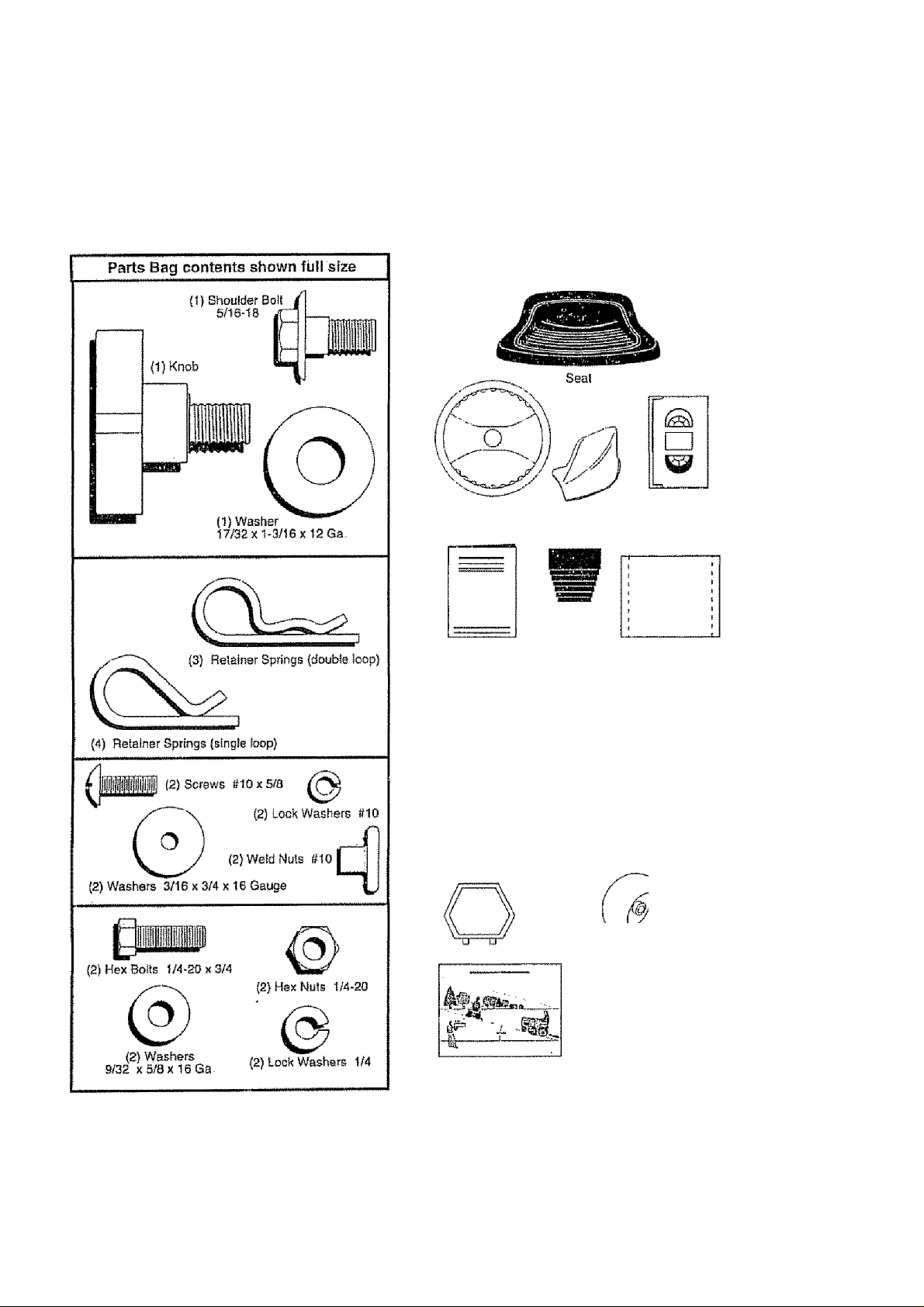
CONTENTS OF HARDWARE PACK
Parts packed separately In carton
Steering
Whesi
Manual
Mulcher
Plate
Steering
Sleeve
Video
Cassette
Parts Bag
Parts bag contents not shown full size
¡2) Washers 3/B
{2) Shoulder
Bolls
(2) Center'
lock Nuts
(2) Front Link Assemblies
Steering
Wheel
Insert
X 7/8x14 Gauge
IJ
'^(2) Gauge
Wheels
Slope Sheet
(2) Keys
Cl^£i=rz=a
latch Hook
Assemblies
Page 7
ASSEMBLY
Youf new Iraclor has been assembled at the faclofy with sKception of those parts iait unassembled lor shipping purposes.
To ensure safe and proper operation of your tractor alt parts and hardware you assemble must be tightened securely Use
the correct tools as necessary to tosure proper lightness - '
TOOLS REQUIRED FOR ASSEMBLY
A sachet wrench set will make assembly easier Standard
wrench sizes are listed,
(2) 7/16" wrenches Piters
(1) 9/16" wrench Tire pressure gauge
(1) 3/4" Socket w/drive ratchet Phillips Screwdriver
Utility knife
When right or left hand is mentioned In this manual, it
means when you are in the operating position (seated
behind the stserihg wheel)
TO REMOVE TRACTOR FROM CARTON
UNPACK CARTON
• Remove all accessible loose parts and parts cartons
irom carton (See page 6).
• Cut, from top to bottom, along lines on all four corners
of carton, and lay panels flat
• Remove mower and packing materials
• Check lor any additional loose parts or cartons and
remove-
FIG. 1
BEFORE ROLLING TRACTOR OFF SKID
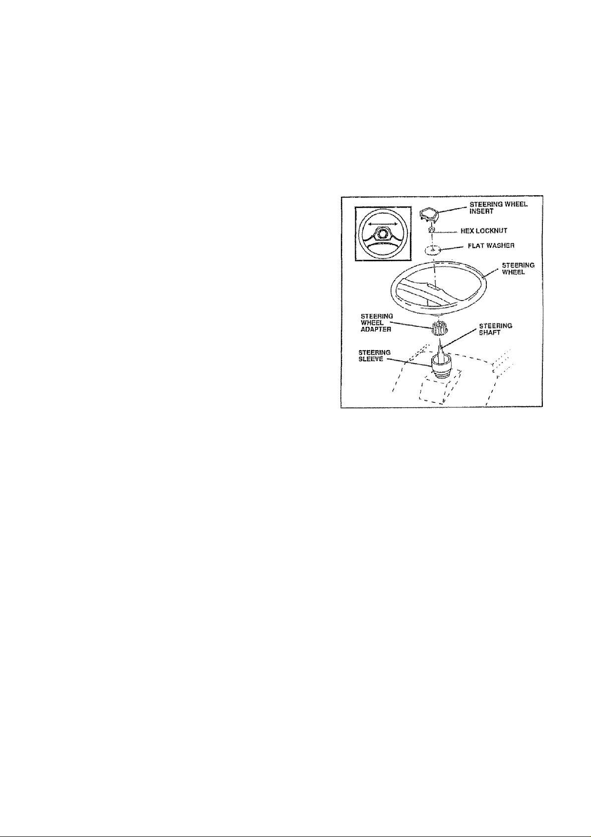
ATTACH STEERING WHEEL (See Fig. 1)
' Remove locknut and large flat washer from steering
shaft-
• Position front wheals of the tractor so they are pointing
straight forward
• Slida the steering sleeve over the steering shaft
• Position stsering wheel so cross bars are horizontal
(left to right) and slide onto adapter
• Secure steering wheel to steering shalt with locknut
and targe flat washer pravlously removed, Tighten
securely.,
• Snap stsering wheel insert into center of steering
wheel.
• Remove protective materials from tractor hood arrd
grilt-
lIVtPORTANT; CHECK FOR AND REMOVE ANY STAPLES
IN S KtO TH AT M AY P UNCTU RE TIRESWHERET RAGTOR
IS TO ROLL OFF SKID
TO ROLLTRACTOR OFF SKID (See Operation
section for location and function of controls)
• Prsssllftleverpiungerand raise attachment lilt Isverto
its highest position.
• Release parking brake by depressing dutch/brake
pedal
• Place freewheel control in freewheeling position to
disengage transmission (See 'TO TRANSPORT' In
the Operation section of this manual)
» Roll tractor backwards off skid.
Page 8
ASSEMBLY
HOW TO SET UP YOUR TRACTOR
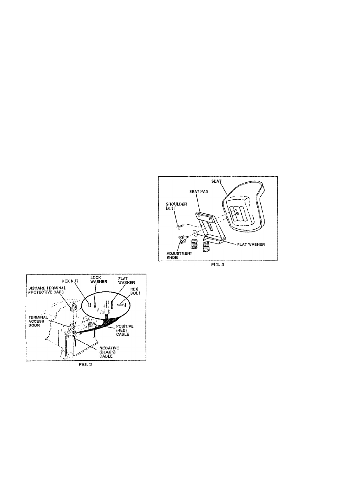
CONNECT BATTERV (See Fig. 2)
CAUTION; Do not short battery termfBals by alio wing a wrench or any other
object to contact both terminals at the
A
• Lif! hood to raised position
• Open terminal access doors, remove terminal protec
• it this battery is put into Service after month and year
• First connect RED battery cable to positive (+j battery
• Connect BLACK grounding cable to negative (-) bat
• Close terminal access doorsUse terminal access doors for:
• inspectton for secure connections {to tighten hard
• Inspsclion lor corrosion
' Testing battery.
» Jumping (if required).
same time, Sefore connecting battery,
remove metal bracelets, wrlstwatch
bands, rings, etc.
Positive terminal must be oormeoted
first to prevent sparking from acciden
tai grounding.
tive caps and discard.
indicated on label {label located between terminals)
charge battery for minimum of one hour at 6-10 amps.
terminal with hex bolt, flatwasher, lock washer and hex
nut as shown. Tighten securaty,
tery terminal with remaining hex boll, flat washer, lock
washer and hex nut, Tighten securely.
ware).
Periodic charging.
fNSTALL SEAT (See Fig. 3)
Adjust seat before tightening adjustment knob.
• Remove cardboard packing on seat pan
• Place seat on seal pan and assemble shoulder bolt.
• Assemble adjustment knob and flat washer loosely.
Do not tighten.
• Tighten shoulder bolt securely.
• Lower seat into operating position and stl on seat.
• Slid« seat until a comfortable position is reached which
allows you ¡0 press clutciVbrake pedal all the way
down
» Get off seat without moving its adjusted postlion..
• Raisa seal and ilghtert adjustment knob securely.
CHECK TIRE PRESSURE
The tifss on your tractor were overinflaled at the factory lor
shipping purposes- Correct tire pressure Is Important tor
best cutting performafioe.
• Reduce tire pressure to PS! shown in ''PRODUCT
SPECIFlCATiONS” on page 3 of this manual
CHECK BRAKE SYSTEM
After you ieam how to operate your tractor, check la ses
that the braka is properly adjusted. Ses “TO ADJUST
BRAKE" in the Service and Adjustments section d1 this
manual.
Page 9
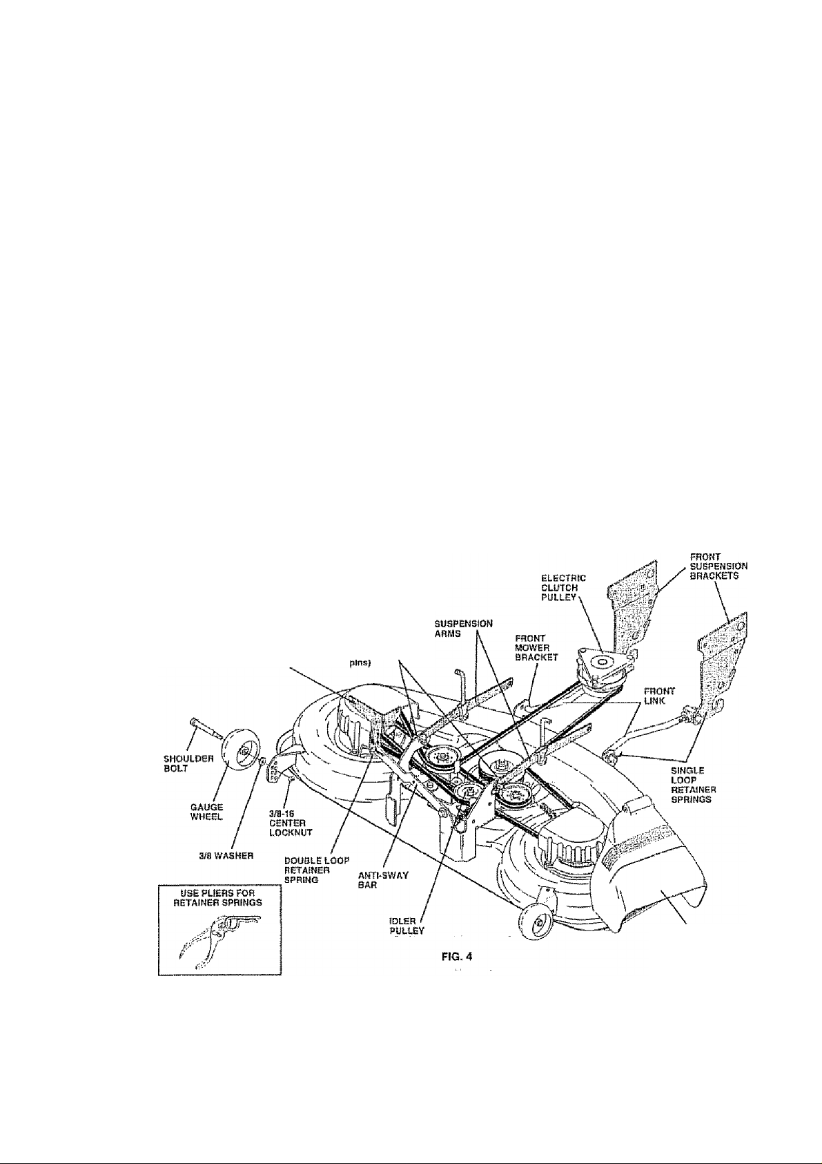
ASSEMBLY
INSTALL MOWER AND DRtVE BELT
(See Figs. 4 and 7)
Ba sure iraclor is on level surface and mower sospenston
arms are raised with aitachmeni lift conirol,. Engage park
ing brake.
• Cut and remove ties securing anti-sway bar and balls.
Swing anti-sway bar to left side of mower deck.
• Slide mower undartractor with discharge guard to right
side of tractor,
IMPORTANT: CHECK SEIT FOR PROPER ROUTING IN
ALL MOWER PULLEY GROOVES. INSTALL BELT INTO
ELECTRIC CLUTCH PULLEY GROOVE.
• Install one front link In top hole of the H.H., front mower
bracket and R.H. front suspenatoh bracket. Retain
with two single loop retainer springs as shown
• Install second iron! link In L. H, front suspenslort bracket
only and retain with single loop retainer spring as
shown.
• Turn height adjustment knob counterclockwise until it
stops
» Lower mower linkage with aitachmeni lift control.
• Place the L.H, suspension arm on outward pointing
deck pin. If necessaty, rock and raise front of mower
to align deck pin wlln the hole in suspension arm
Retain with double loop retainer spring with loops
down as shown,
Slide left side oi mower back a nd install the unattached
front link in top hots of the LH, front mower bracket.
Retain with single loop retainer spring as shown
DOUBLE LOOP
rtSTAlNEB SPRING
(OUlWJircl pOPRilnp
deck ■ '
• Place the R.H suspension arm on outward pointing
deck pin. if necessary, rock and raise front of mower
to align deck pin with the hols in suspension arm.
Retain with double loop retainer spring with loops down
as shown
• Connect anti-sway bar to chassis bracket under left
footrest and retain with double loop retainer spring
• Turn height adjustrrrent knob cloclcwlss to remove
slack from mower suspension.
• Raise mower to highest position.
• Assemble gauge wheels (See ”TO ADJUST GAUGE
WHEELS" in the Operation ssction of this manual).
CriBC^fv MOwvBiFt lf#BVBL-NBoS
For best cutting results, mower should be property leveled,
See “TO LEVEL MOWER HOUSING" in the Service and
Adjustments section of this manual.
CHECK FOR PROPER POSITION OF ALL
BELTS
See the figures that are shown for replacing motion, mower
drive, and mower biada drive belts in the Service and
Adjustmenis section of this manual Verify that the belts
are routed correctly
DISCHARGE GUARD
Page 10
ASSEIVIBLY
IhhF ■ M i IlHF llMI S
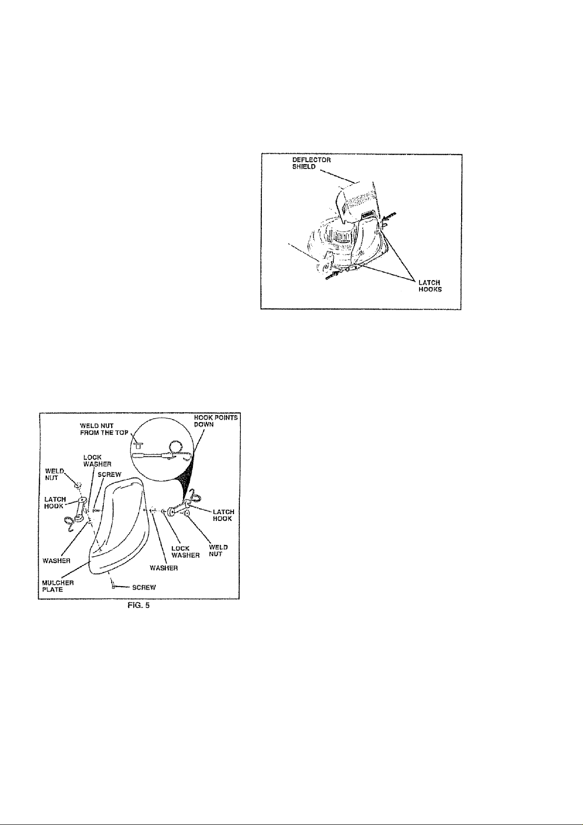
NSTALL iviuLCHER PLATE (See Figs, 5 ana 6)
• tnslall two ialcfi hooks to mulcfier ptote using screw,
washer, lock washer, and weld nui as shown,
NOTE: Pre-assemble weld nul to latch hook by inserting
weld nut from the lop with hook pointing down-
• Tighten hardware securely,
• Raise and hold deitecfor shield in upright position.
• Place troni of mulcher plate over front of mower deck
operiing and slide into place, as shown,
• Hook front iatch into hole on front of mower deck.
• Hook rear latch into hole on back of mower deck
CAUTiON: Do not remove discharge
guard from mower. Raise and hold
guard when attaching muicher plate
and aliow it to rest on plate while in
opamtlon.
FIG. 6
TO CONVERT TO BAGGING OR
DISCHARGING
Sfmpfy remove muicher plate and store in a safe ptace.
Your mower is now ready tor discharging or instatlallon of
optional grass catcher accessory,
NOTE: it is not necessary to change biadss. The muicher
blades are designed for discharging and bagging ateo
^CHECKLIST
BEFORE YOU OPERATE AND ENJOY YOUR NEW
TRACTOR. WE WISH TO ASSURE THATYOU RECEIVE
THE BEST PERFORMANCE AND SATISFACTION FROM
THIS QUALITY PRODUCT
PLEASE REVIEW THE FOLLOWING CHECKLIST;
/ All assambly Insirucllons have been compieted
/ No remaining loose parte in carton.
/ Battery Is properly prepared and charged {Minimum
1 hour at 6 amps),
/ Seat is adjuslsd comfortably and tightened seciireiy.
/ All tires are properly inflated. (For shipping purposes,
the tires were overfnflaled at the factory).
/ Be sure mower deck is properly iaveled s(deHo*side/
front-to-rear for best cutting rasuits, (Tires must be
properly Irttlated tor ieveling),
/ Check mower and drive belts. B e sure they are routed
properly around pulleys and inside ati belt keapars.
/ Check wiring. See that alt connect tons a re still secure
and wires are properly clamped.
/ Before driving tractor, be sure freewheel control is In
drive position
WHILE LEARNING HOW TO USE YOUR TRACTOR. PAY
EXTRA ATTENTION TO THE FOLLOWING IMPORTANT
ITEMS;
/ Engine ollls at proper levs!.,
/ Fuel tank Is fiiied with fresh, clean, regular unleaded
gasoline,
/ Become familiar with all conirois ' their location and
lunGtion. Operate them before you start the eriptne,
/ Be sure brake system is irr safe operating condition.
/ It is important to purge the transmission before operat
ing your tractor for the first Urns Foliow proper starting
and irarismlsstorr purging Instructions (See 'TO START
ENGINE" and "PURGE TRANSMISSION" In the Op
eration section o! this manual).
10
Page 11

OPERATION
These symbois may appsaron your traoior or tn Dtarafore suppfted with the product- Learn and itrtdersiand their meaning
n A $
BATTERY
©
ENGINE ON
a
FUEL
Ik
Í
CAUTION OR
WARNING
STOP
ENGINE OFF
REVERSE FORWARD
OIL PRESSURE
l\l £
CHOKE MOWER HEIGHT
D
n
REVERSE
N
NEUTRAL
.Î.
FAST SLOW
4 a| a
CLUTCH LIGHTS ON LIGHTS OFF
© G?
differential PARKING BRAKE
LOCK LOCKED
H L
HIGH LOW
(©)II
PARKING BRAKE
UNLOCKED
If
MOWER LIFT
DANGER, KEEP HANDS AND FEET AWAY
ATTACHMENT
CLUTCH ENGAGED
ATTACHMENT
CLUTCH DISENGAGED
HYDROSTATIC FREE WHEEL
(Hydro Models only)
11
IGNITION
Page 12
OPERATION
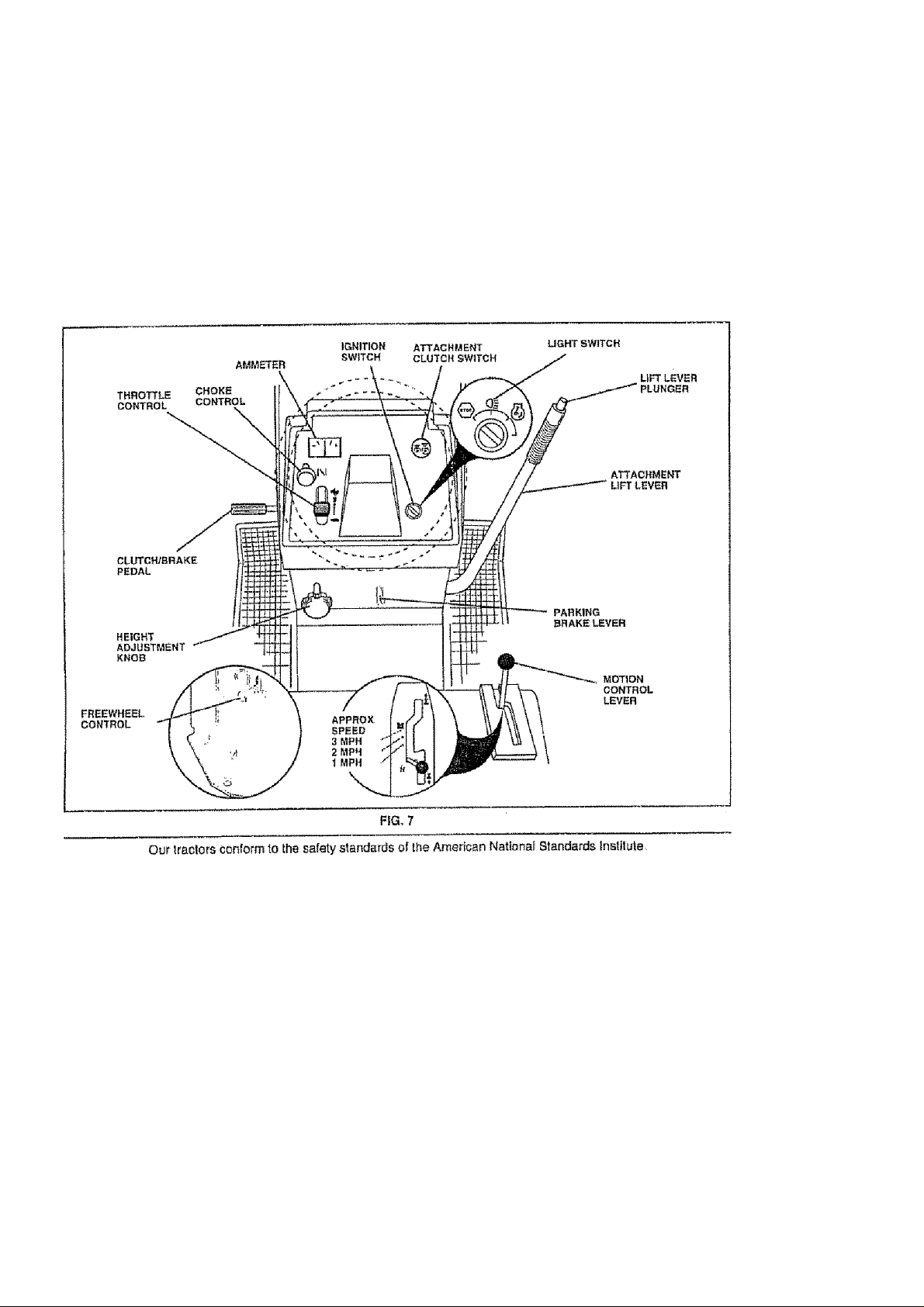
KNOW YOUR TRACTOR
READ THIS OWNER’S MANUAL AND SAFETY RULES BEFORE OPERATING YOUR TRACTOR.
Compafe the Illustrations with your tractor to familiarize yourself with the location ol various controls and adjustments - Save
this manual for luture reference, ,
ATTACHMENTCLUTCH SWITCH' Usedtoarrgagemower
blades or other attachments mounled to your tractor
ATTACHWIENT LIFT LEVER - Used to raise and lower
mower deck or other attachments mounted to your tractor,
CLUTCH/BRAKE PEDAL - Used for declutching and
braking the tractor and starting the engine,
HEIGHT ADJUSTMENT KNOB - Used to adjust the mower
height, ,
LIGHT SWITCH - Turns the headlights on and off,
MOTION CONTROL LEVER *- Selects the speed and
dtreciion of the tractor.
12
IGNITtON SWITCH - Used !o slart and stop the engine
PARKING BRAKE LEVER - Locks ciutch/brake peda! into
the brake position.
THROTTLE CONTROL - Used to conirof atrgine speed.
LIFT LEVER PLUNGER - Used to release attachment lift
lever when changing Its position,
CHOKE CONTROL - Used when starting a cold engine
AMMETER - Indicates charging (t) or dischatgIrtg (-) of
battery
FREEWHEEL CONTROL - Disengages Iransrnission for
pushing or slowly towing the tractor with the engine o!f
Page 13
OPERATION
The operation of any tractor can result in foreign objects thrown into the eyes, which can
result In severe eye damage. Always wear safety glasses or eye shields while operating
your tractor or performing any odjostmenls or repairs. We recommend a wide vision safety
mask over the spectacles or standard safety glasses.
HOW TO USE YOUR TRACTOR
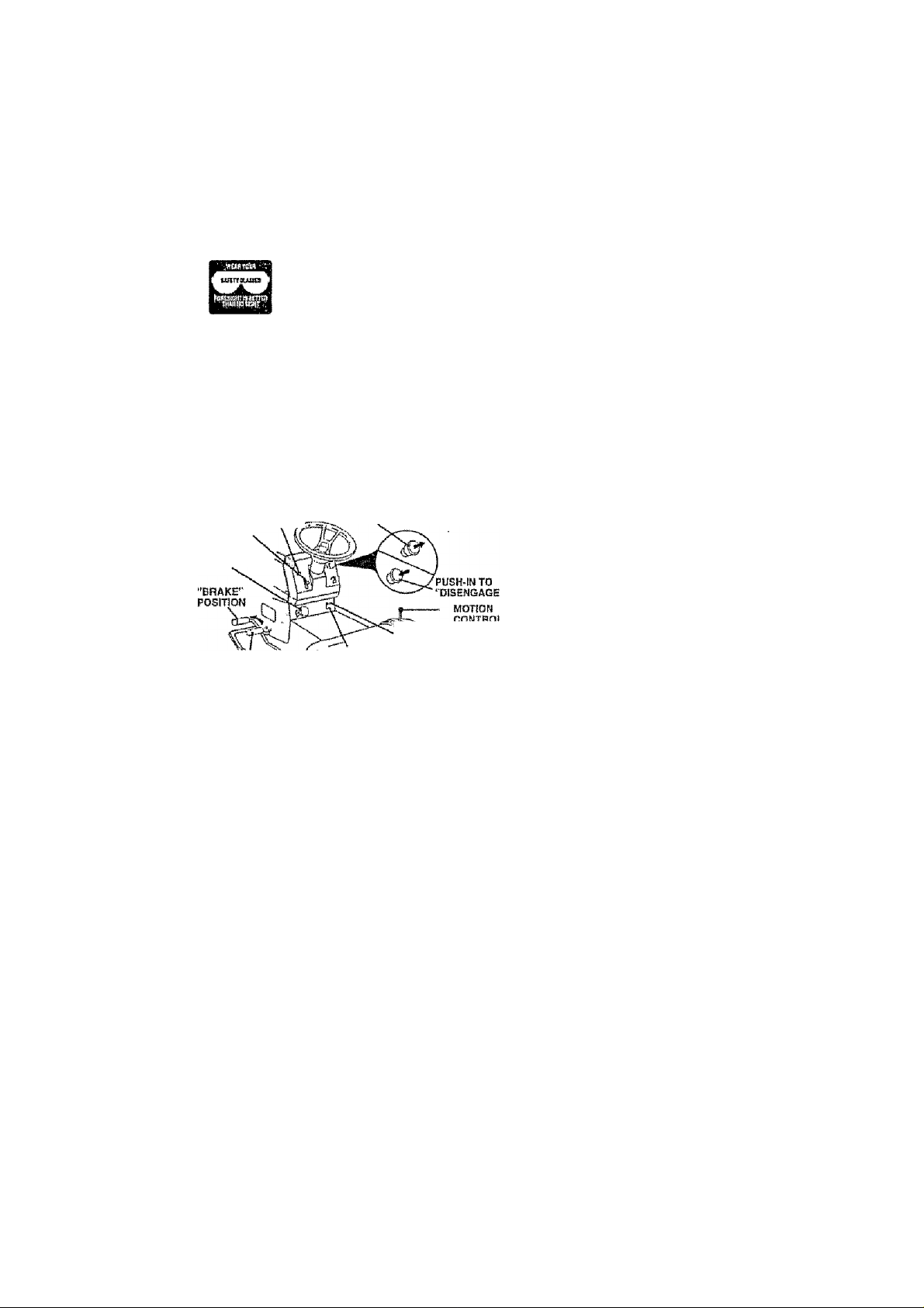
TO SET PARKING BRAKE (See Fig. 8)
Youf tractor Is equipped with an opsrato r presence sensing
switch. When engine Is running, any attempt by the
operator to leave the seat without lirst satling the parking
brake wiil shut off the engine
• Depress clutchArake pedal Into full "BRAKE" position
and hold.
• PtacB parking brake lever in "ENGAGED” position and
release pressure Irofn ciutch/braks pedal, Pedal should
remain in "BRAKE"position, Maks sure parking brake
will hold iractor secure.
THflOTTΠCONTROL
CONTROU
HEIGHT
ADJUSTPEMT
KNOB
CLUTCHfflRAKE PEDAL
"DRIVE" POSITION
CHOKE
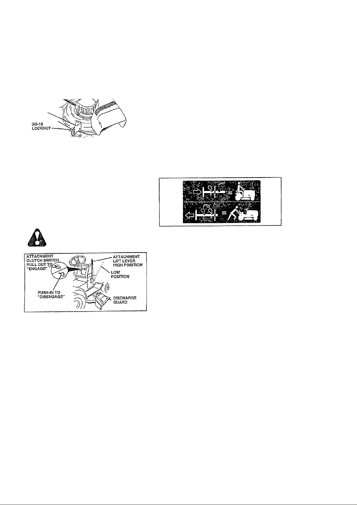
ATTACHMENT CLUTCH SWITCH
PULL OUT TO "ENGAGE"
'■"DISENOAOED” "ENGAGEB"
POSrnOH POSITION
PARKING Brake
FIG, 8
STOPPING (See Fig. 8)
MOWER BLADES -
• Move atlachment clutch switch to “DISENGAGED”
position
GROUND DRIVE -
• Depress clulch/brake pedal into full "BRAKE" position.
• Move motion control lever to neutral (N| position.
IMPORTANT: THE MOTION CONTROL LEVER DOES
NOT RETURN TO NEUTRAL (N) POSITION WHEN THE
CLUTCH/BRAKE PEDAL IS DEPRESSED
ENGINE -
• Move throttle control to stow position -
NOTE; Failure to move throllle control to slow position and
allowing engine to Idle before stopping may cause engine
to "backfire",
• Turn Ignition key to "OFF" position and remove key.
Always remove key when leaving tractor to prevent
unauthorlzBct use,
• Never use choke to stop engine
NOTE: Under certain conditions when tractor Is standing
idle with the engine running, hot engine exhaust gases may
cause '‘browning’’ of grass. To eliminate this possibility,
always stop engine when stopping Iractor on grass areas
CAUTION: Always stop tractor com
pletely, as described above, before teav-
A
Ing the operator's position; to amply
grass catoher, ate.
13 sama adjustment hole
TO USE THROTTLE CONTROL (See Fig, 8)
Always operate engine at full throttle.
• Operating engine at less than full fhrotlfe reduces the
battery cBarging rate
• Full throille offers the best mower performance,
TO USE CHOKE CONTROL (See Fig. 8)
Use choke eonfrol whsneveryou are starting a cold engine
Oo not use to start a warm engine
• To engage choSo control, puilknob out Slowly push
knob in to disengage
TO MOVE FORWARD AND BACKWARD (See
Ffg. 8)
The direction and speed of movement is controlled by the
mofion conlrol lever.
• Start tractor with motion control lever In neutral (N)
position,
• Release parking brake and clutcb/brake pedal
• Slowly move motion control ¡ever to desired position
TO ADJUST MOWER CUTTING HEIGHT
(SeB Fiq. 8)
The cutting height is controlled by turning the height adjust
ment knob in desired direction,
• Turn knob clockwise to raise cutting height
• Turn knob Gotmterolockwiss {K~>) to lower cutting
height.
The cutifng height range is approximately 1-1/2" to 4“ The
heights are measured from the ground to the blade lip with
the engine not running These heights are approximate
and may vary depending upon soil Gondllions, height of
grass and types of grass being mowed,
• The average lawn should be cut to approximately 2-1/2
inches during the cool season and to over 3 inches
during hot months. For heailtiier and belter looking
lawns, mow oUen and after moderate growth
• For best cutting performance, grass over e inches in
height should be mowed twice. Make the first cut
relatively high; the second to desired height
TO ADJUST GAUGE WHEELS (See Fig. 8)
Gauge wheels are properly adjusied when they are slightly
off the ground when mower is at the desired culting height
In operating position. Gauge wheels then keep the deck in
proper position to help prevent scalping in most terrain
conditions
• Adjust gauge wheels wlih tractor on a Hat level surface
• Adjust mower to desired cutting height [See 'TO AD
JUST MOWER CUTTING HEIGHT in the Operation
section of this manual),
• With mower in desired height of cut position, gauge
wheels should be assembled so they are slighily off the
ground. Install gauge wheel in appropriate hole with
shoulder boil, 3/3 washer, and 3/B-16 locknut and
tighten securely,
• Repeat for opposite side installing gauge wheel in
Page 14
OPERATION
GAUESE WHEEL
MOUNTIHQ
BRACKET
3/a WASHER
GAUGE WHEEL ■
TO OPERATE MOWER (See Fig. 10)
Your tractor !a equipped with an operator presence sensing
switch. An^ attempt by the operator to leave the seat with
the engine running and the attachment ciuteh engaged will
shut oJf the englrte-
• Sslact desired height of cut-
• Lower mower with attachment lift control,
• Start mower blades by engaging attachment clutch
control.
- TO STOP MOWEH BLADES - disengage attachment
clutch control.
CAUTION; Do not operals the mower
without either the entire grass catcher,
on mowers so equipped, or the dis
charge guard In place.
TO OPERATE ON HiLLS
CAUTION: Do not drive up or downhills
with slopes greater than IS“ and do not
drive across any slope.
• Choose the slowest speed before starting up or down
hills.
• Avoid Stopping or changing speed on hills,
• (f slowing is necessary, move throttle controi lever to
slower position.
• ft stopping is absolutely necessary, push ciutchfbrake
pedal qufckty to brake position and engage parking
Brake,
• Move motion control lever to neutral (N) position,
Ifi/IPOBTANT: THE MOTION CONTftOL LEVER DOES
ШТ RETURN TO NEUTRAL (N) POSITION WHEN THE
CLUTCH/BRAKE PEDAL IS DEPRESSED
• To restart tnovament, slowly release parking brake and
olufchfbrakB pedal
• Slowfy move motion control lever to slowest setting.
• Маки ail turns siowlv.
-------BOLT
FIG. 9
* •
FIG. 10
J' ,4,71 SHOULDER
14 rtamaoB mav occur.
TO TRANSPORT (See Fig. 11)
When pushing or towing your tractor, be sure to disengage
IransmtBsion by placing freewheel control in freewheeling
position. Free wheel control is located at the rear drawbar
of tractor,
• Raise attachment lift to highest position with attach
ment lift control
• Puli freewheel control knob out and hold in position by
inserting retairrs rsprlng I nto forward hole of control rod.
• Do not push or tow tractor at more than two (2) У PH.
• To »engage transmission, reverse above procedurs,.
NOTE: To protect hood from damage when Iransportlng
your tractoron atruckor a trailer, be sure hood Is closed and
secured to tractor. Use an appropriate means of tying hood
to tractor (ropB, cord, etc).
FIG. 11
BEFORE STARTING THE ENGINE
CHECK ENGINE OIL LEVEL {See Fig. 18)
' The engine in your tractor has been shipped, from the
(actory, already filled with summer weight oi(
• Check engine oil with tractor on level ground.
■ Remove olì fill cap/dipslick and wipe clean, reinsert the
dipstick and push It all the way down into the tubs, wait
for a few seconds, remove and read oil level. If
necessary, add oil until TULL" mark on dipstick Is
reached. OonotoverfiìL
• For cold weather operation you should change oil for
easier starting (See '"OIL VISCOSITY CHART" In the
Customer Responsibilities saction of this manual).
• To change engine oil. see the C ustomer Responsibili
ties section in this manual
ADD GASOLINE
• Fill fuel tank Use fresh, clean, regular unleaded
gasoilne with a minimum of 07 octane. (Use of leaded
gasoline will Increase carbon and lead oxide deposits
and reduce valve lilei. Do not mix oil with gasoline.
Purchase fuel irt quantities that can bs used within 30
days to assure fuel freshness
typOBTANT: WHEN OPERATING IN TEMPERATURES
BELOW SS^EKTC). USE FRESH, CLEAN WINTER GRADE
GASOLINE TO HELP INSURE GOOD GOLD WEATHER
STARTING
WARNING; Experience Indicates lhal alcohol blended
fueis (called gasohoi or using ethanol or msfhanoi) can
attract moislurs which leads to separation and lormatlon of
adds during storage. Acidic gas can damage the fuel
system of an engine white In storage. To avoid engine
problems, the fuel system should be emptied before stor
age of 30 days or longer. Drain the gas tank, start the
engine and tei it run until the fuel lines and carburetor are
empty. Use fresh fusi next seasori. See Storage Instruc
tions for additional information. Never usa engine or
carburetor cleaner producis In the fuel tank or permanent
Page 15

OPERATION
CAUTION: Fill to bottom of ges tank
filter neck, Oo not overfill. Wipe off any
A
spilled oi! or fuel. Do not store, spill or
USB gasoline near art open (lame.
TO START ENGINE (See Fig. 8)
When starting the engine for the first time or if the engine
has run out of fuel, It wiil take extra cranking time to move
fuel from the tank to the engine,
• Ba sure freewheel control is in the transmission en
gaged position.
• Sit on seat in operating position, depress clutch/brake
pedai and set parking brake
• Pfaoe motion cortlrol lever in neutra! (N) position
• Move attachment clutch to "DISENGAGED" posiiion
• Move throtlie control to fast position
» Pull choke control oul tor a cold engine start attempt
For a warm engine start attempt the choke control may
not be needed- .
Note: Before starting, read the warm and cold starting
procedures below
• Insert key into Ignition and turn key ciockwise io"START
position and reiease key as soon as engine starts Do
not run starter conitmiQusly lor rnore than fifteen sec
onds per minute if lha engine does not start after
several attempts, push choke control in, wait a few
minutes and try agairt, if engine still does not start, pul!
the choke control oul and retry
WARM WEATHER STARTING {50° F and above)
• When engine starts, slowly push choke conlrot In urilil
the engine begins to run smoothiy. If the engine starts
to run roughly, pull the choke control oul slightly for a
lew seconds and then continue to push the control in
slowiy
« The attachtnenls and ground drive can now be used. it
the engine does not accept the load, restart the engine
and allow it to warm up lor one minute using the choke
as described above
COLD WEATHER STARTtNG (50" F and beiow)
' When engine starts, slowly push choke contro! In until
the engine begins to run smoothiy Continue to push
the choke control in small steps aifowlng the engine to
accept small changes in speed and load, until the
choke control is fully in. If the engine starts to run
roughly, puli the choke control out slightly for a few
seconds and then continue to push the control in
slowly. This may require art engine warm-up period
from several seconds to several minutes, depending
on the temperature.
HYDROSTATIC TRANSMISSION WARM UP
• Before driving the unit In cold weather, the transmis
sion should be warmed up as lollows;
• Be sure the tractor is on level ground.
• Piace the motion control iever in neutral.
Reiease the parking brake and let theclulch/brake
slowly ratum to operaling position,
• Allow one minute (or trarrsmisBlon to warm up.
This can be dons during the engine warm up
period
’ The attachments ca n be used during the engine warm
up period after the transmission has been warmed up
and may require the choke control bo pulled oul slightly.
15
NOTE; If at a high altitude (above 3000 feet) or in cold
Eemperalofes (below 32 F) the carburetor fuel mixture may
need to be adjusted for best engine performance. See “TO
ADJUST CARBURETOR" In the Service and Adjustments
section of this manual.,
PURGE TRANSMISSION
CAUTION: Never engage or disengage
£k
m
To ensure proper operation and perlormanca, It is recom
mended that the transmission be purged before operating
tractor for the first time. This procedure wili remove any
trapped air inside the transmission which may have devel
oped during shipping of your tractor
IMPORTANT; SHOULD ¥OUR TRANSMISSION REQUIRE
REMOVAL FOR SERVICE OR REPLACEMENT, IT
SHOULD BE PURGED AFTER REINSTALLATION
BEFORE OPERATING THE TRACTOR.
• Place tractor saieiy on level surface with engine off and
• Disengage transmission by piecing freewheel control
• Si(tinglntheifactorseat,startengine After the engine
• Move motion control iever to full forward position and
NOTE: During this procedure iitere will be no movement of
drive wheels. The air Is being removed from hydraulic drive
system-
• Move motion controi iever to neutral (N) position. Shut
• Engage transmission by placing freewheel control in
• Sitting in the tractor seat, start engine. After the engine
• Slowly move motion controi lever forward, alter the
• Your, tractor Is now purged and now ready for normal
freewheel lever while the engine is run
ning.
parking brake set
In freewheeling position (Ses "TO TRANSPORT in
this section of manual)
is running, move Ihrollfe control to slow posiiion. With
motion control lever in neutrai (N) position, slowly
disengage clutch/brake pedal,
hold lor five (5) seconds. Move lever to fu!l reverse
posiiion and hold for five (6) seconds- Repeat this
procedure liime (3) times.,
off erigine and set parking brake,
driving position (See “jO TRANSPORT in this section
of manual)
is running, move throttle control to half (1/2) speed.
With motion corrtrol ¡ever In neutral (N) position, slowly
disengage ctutch/brake peda!
tractor moves approximately five (5) feet, slowly move
motion control lever to reverse position. After the
tractor moves approximately live (5) feet return the
motion control Isverto the neutrai (N) position. Repeat
this procedure with the motion contro! ¡ever ihres (3)
times,
operation
Page 16
OPERATION
MOWING TIPS
• Tire chains cannoS be used when the mower housing is
attached to tractor
• Mower should be property ieveled for best mowing
performance- See 'TO LEVEL MOWER HOUSING" in
the Service and Adjustments section of this manual.
• The left hand side of mower should be used for trimmini,
• Drive so that clippings are discharged onto the area
that has been cut Have the cut area to the right of the
machine. This will resull in a more even dislribution of
dippings and more urrifortn cutting.
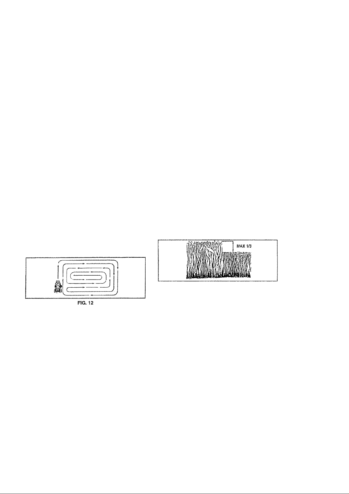
• When mowing large areas, start by turning to the right
so that clippings will discharge away from shrubs,
fersoes, driveways, etc. After one or two rounds, mow
in the opposite direction making left hand turns unfll
finished {See Fig. 12)..
• if grass is extremely tali, it should be mowed iwice to
reduce toad and posslbie fire hazard from dried cilpplngs. Make first cut reiaiiveiy high; ths second to the
desired height
• Do not mow grass when it is wet, Wet grass will plug
mower and ieave undesirable ciumps, Allow grass to
dry before mowlng.
• Always operaie engine at futí throftle when mowing to
assura better mowing performance and proper dis
charge of material. Regulate ground speed by select
ing a low enough gear to give I he mower cutting
performance as well as the qualify of cut desired
• Whan oparating attachments, select a ground speed
that wii! suit the terrain and give best performance of
the attachment being used.
MULCHING MOWING TIPS
ttiPOfîTANT; FOR BEST PERFORMANCE. KEEP
MOWER HOUSING FREE OF BUîLT-UP GRASS AND
TRASHi CLEAN AFTER EACH USE
• The special mulohlng blade will rscut Ihe grass clip
pings many times and reduce them in size so that as
they fall onto the lawn they will disperse into fhe grass
arto net be noticed. Also, the mulched grass wiii
biodegrade quickly to provide nutrients for the lawn.
Always mulch with your highest engine (blade) speed
as this will provide the best recutting action of ths
blades,
• Avoidcuttingyouriawnwhenitlswet Weigrasstends
to form clumps and Interferes with the mulching action
The bast time to mow your lawn Is the early aflsmoon.
At ihlstime the grass has drlsd and the newly cut area
wifi not be exposed to tha direct sun.
• Forbesf results, actjustthe mower cuHing height so that
the mower cuts off oniy the fop one-third of the grass
blades {See Fig. 13) For extremely heavy mulcting,
reduce your width of cut on each pass and mow slowly.
• Certain types of grass and grass conditions may re-
(*isiitria fKa! ¡sfrctisi Hci itïhÎaKîsH a cor'rntTf^ ilma Itî r>rrtn-
LjLIîf Lr \r rC*4 îrt11 ^+1 wCt Liw Î Ï ^wI IL# li I i Ifc* IL^ vLrl 11
pletely hide the dippings. When doing a second cut,
mow across or perpendicular to the first cul path.
• Change your cutting pattern from week to week- Mow
north to south one week then change to east to west the
next week, This will help prevent malting and graining
of the lawn..
16
FiG. 13
Page 17

CUSTOMER RESPONSIBILITIES
MAINTENANCE SCHEDULE
FILL IN DATES
AS YOU COMPLETE
Check Brake Oporallon ,
Check Tire Prasaurs
Cheek tor Loose Fasteners
Shafpen/PtAplAca Mower Blades
Lubrication Chert
Check Satisfy LeveWTecharge
Clean Baltery and Terminals
Check Tránsasele Cooling
Adjust Blade BelSCs) Tension
Adjust Motion Drive Bel!(s) Tension
Check Errgine Oil Level
, Changa Engine OH ,
Ctean Air Filter
Clean Air Screen
Inspect Mullier/Spsrk Arrester
Replace Oli Filter (It equipped)
Clean Engine Cooling Fins tr'2
Replace Spark Plug
Replans Air Filler Papar Cartridge
Replace Fuel Filler
Î • more ofien wiicn oparailng under a haavy toad or In high ambisfii toinpsratUicssi
2.« Sfifvtea ^CTQ flllon whî3n operaling In dlity or dosly tondMIons
3 - ir equipped wiHi ¿1! llllGf, chsrtp o9 every 50 hoMiS-
4 '■ Replaça blades mcfo pfton when mpwlfts in sandy self
✓ ✓
✓ ✓
✓
✓
t/
1/ ✓
1/
l><2,3
✓ a
GENERAL RECOMMENDATIONS
The warranty on Shis Sractor does not cover items thaS have
been subjected to operator abifse or negligence- To
receive full value from the Warranty, ope rator must mainlain
tractor as instruciad !n this manual.
Some adjustments will need to be made perlodleatly to
properly maintain your tractor.
Alt adjustments In the Service and Adjustments section at
this manual should bs checked at least once each season.
• Once a year you should replace the spark plug, clean
or replace air filler, and check blades and bsiis for
wear. A new spark plug and clean air filter assure
proper air-fuel mixture and help your engine run better
and last longer
(D SPINDLE ZERK gp^OLE ZERK®
® FRONTWHEEL-^"
©ATTACHMENT
t/v
1/
î/s
l/i
✓
*/
V^.2
i/
«/
✓ 2
1/
5 ■■ If equipped adjuBtablo systom,
B ' Ngi required If equipped vrfsb rnalnlenar^ce-hert baHsry
7 ■ Tlghien frsnl ails pivoi ttoll W 35 ft •■lbs maximum
Do no? ovefflgWen.
LUBRICATION CHART
BEARÎNG ZERK LL
CLUTCH
PiVOTfS)
FRONT WHEEL®
BEARING ZERK
'ENGINE®
BEFORE EACH USE
• Check engine oil level.
► Check brake operation
» Check tire pressure.
• Check for loose fasteners.
© SAÊ 30 OR tBW30 MOTOR OIL
® GENERAL PURPOSE GREASE
(D fjEpER TO CUSTOMER RESPONSIBIUTIES "ËNG1KE" SECTION
IMPORTANT: DQ NOT OIL OB GREASE THE P1VOT POINTS
WHICH HAVE SPECIAL NYLON BEARINGS, VISCOUS LUBRI
CANTS WILL ATTRACT DUST ANO DIRT THAT WILL SHORTEN
THE LIFE OF THE BELF-LUBRtCATINQ BEARINGS. tF YOU
FEÊL THEY MUST BE LUBRICATED, USE ONLY A DRY, POW-
■¡7 DEREO GRAPHITE TYPE LUBRICANT SPARINGLY-
Page 18
CUSTOMER RESPONSIBILITIES
TRACTOR
Always observe saleiy rules when periarming any mainte
nance,
BRAKE OPERATION
!f tractor requires more than six (6) feet stopping distance
at high speed in highest gear, then brake must be adjusted,
(See “TO ADJUST BRAKE" In the Service and Adjust
ments section of this martual).
TIRES
• Maintain proper air pressure In ail tires (See “PROD
UCT SPECIFICATtONS" on page 3 of this mantiai|,
• Keep tires free o! gasoline, oil, or Insect control chemi
cals which can harm rubber,
• Avoid stumps, stones, deep ruts, sharp objects and
other hazards that may cause tire damage.
NOTE: To seat tire punctures and prevent fiat tires dua to
slow teaks, lira sealant may be purchased from your iocai
parts dealer. Tire sealant also prevents tire dry rot and
corrosion,
BLADE CARE
For best results mower blades must be kepi sharp. Re
place bent or damaged blades,
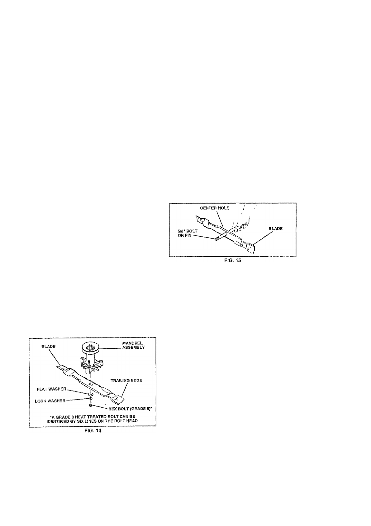
BLADE REMOVAL (See Fig. 14)
• Raise mower to highest position to allow access to
btades-
• Remove hex bait, lock washer and fiat washer securing
blade.
• Install new or resharpened blade with trailing edge up
towards deck as shown.
• Reassemble hex boll, lock washer and flat washer In
exact Older as shown.
• Tighten bolt securely (30-35 Ft Lbs torque)
i MP О RTAN T: BLA D E 8 OLT1S G R ADE a HE AT TR E ATED
NOTE; We do not reconnmend sharpening blade - but if you
do, be sure the blade is balanced.
TO SHARPEN BLADE (See Fig. 15)
Care should be taken to keep the blade balanced. An
unbalanced blade wiil cause excessive vibration and everrtual damage to mower and engine.
• the blade can be sharpened with a 1!te or on a grinding
wheel. Do not attempt to sharpen while on the mower-
• To chsck blade balance, you will naed a S/0’ diameter
steel bolt, pin, or a cone balancer. (When using^ a cone
balancer, follow the inslmotians supplied with bal
ancer.)
• Slide blade on to an unthrsaded portion of the steel bolt
orpin and hold the boll or pin parallel with the ground,
If blade Is balanced, It should remain in a horizontal
position If either end of the blade moves downward,
sharpen the heavy and until the blade is balanced,
NOTE: Do not use a nail for batanclng blade The lobes of
the center hole may appear to be centered, but are not
BATTERY
Your tractor has a battery charging system which Is sulficisnt for normal Use- However, periodic charging oi the
battery with an automotive charger will extend its life.
• Keep battery and terminals dean
• Keep battery bolts tight
• Keep small vent holes open
» Recharge at 6-10 amperes for 1 hour,
TO CLEAN BATTERY AND TERMINALS
Corrosion and dirt on the battery and terminals can cause
the battery to “leak" power.
• Remove terminal guard.
• Disconnect BLACK battery cable first then RED
battery cable and remove battery from tractor.
• Rinse tha battery with plain water arrd dry
• Cleart terminals andbatlery cable ends with wire brush
until bright
• Coat terminals with grease or pelroteum jelly-
• Reinstall battery (See “CONNECT BATTERY' in the
Assembly section of this manual),
IB
Page 19
CUSTOMER RESPONSIBILITIES
V-BELTS
Check V-beits for deierioraiion and wear alter 10G hours of
operation and replace If nacsssary. The bells are not
adjusiabia Replace bells if they begin lo slip from wear
TRANSAXLE COOLING
The fan and cooling fins of IransmissiQfi should be kept
clean to assure proper cooling-
Do not atlampt to clean fan or transmission while engine Is
running or while the transmission Is hol-
• inspect cooling fan to be sure fan blades are infact and
clean
• Inspect cooling tins for dirt, grass clippings and other
materials- To prevent damage to seals, do not use
compressed air or high pressure sprayer to clean
cooiing fins-
TRANSAXLE PUMP FLUID
The transaxle was sealed at the factory and fiuid mainte
nance is not required for the life of the transaxie, Should the
transaxle ever teak or require servicing, cofttact your near
est authortzed service centar/department-
ENGINE
LUBRICATION
Only use high quality detergent oil rated with API service
classilicatlon SF, SG or SH. Select the oH's SAE viscosity
grade according to your expected operating lemperalure.
SAE VISCOSITY SRADES
1 I r
30* M' W 60' SO'
jr
TEMPESATURE RAUBE AtmCiPATEQ SETOSe NEXT Oil CHANSE
NOTE: Aithough multi-vtscosliy oils |SW30,10W30 etc }
Improve Starling irt cold weather, these multi-viscosity oils
will result in increased oil consumption when used above
3a“F. Check your engine oil level more frequently to avoid
possible engine damage from running low on oil
Change the oi! after every 50 hours of operation or at least
onceayearif the tractoris not usedlorSO hours In one year.
Check the crankcase oi! level before starting the engine
and after each eight {B) hours of operation-, Tighten oil fill
cap/dipstick securely each time you check the oil level.
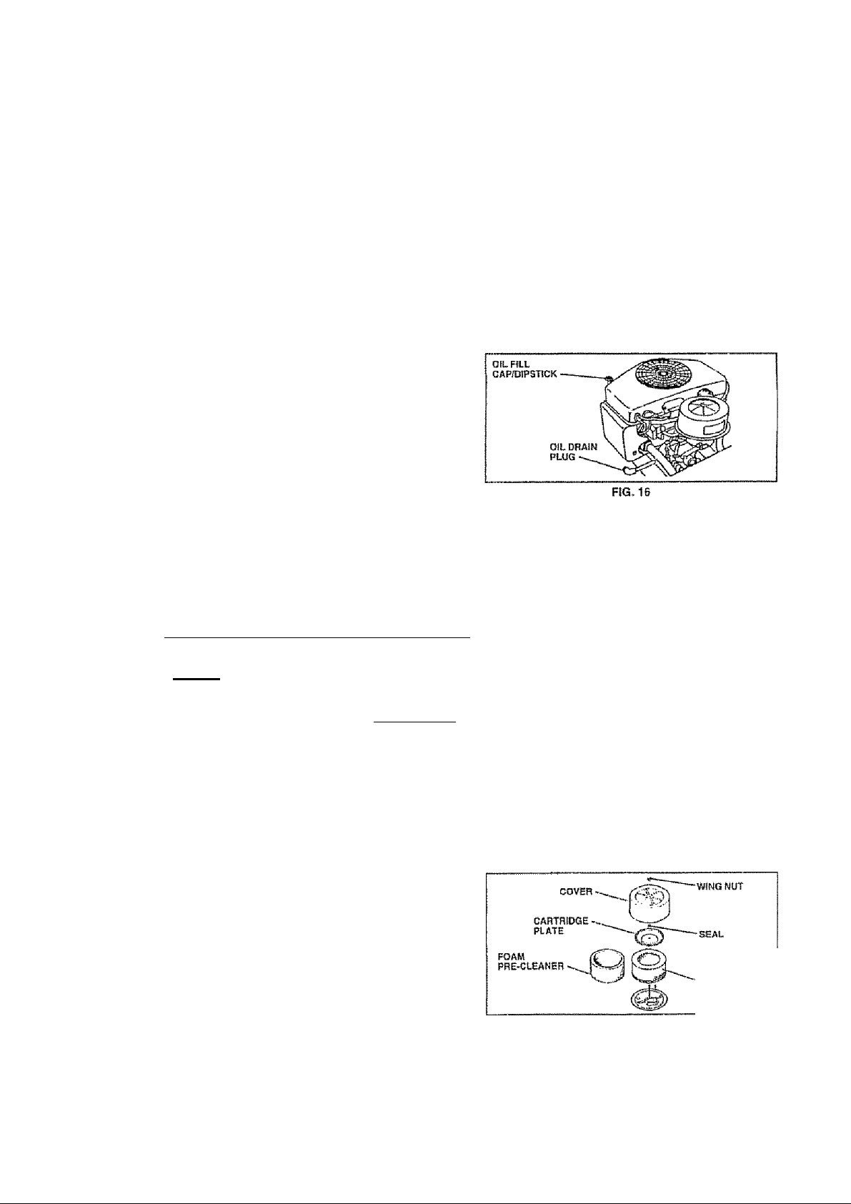
TO CHANGE ENGINE OIL (See Fig. 18)
Determine temperature range expected before oil change.
All oil must meet API service ciasslficaflon SF, SQ or SH.
• Be sure tractor Is on level surface
• Oii will drain more freely when warm.
• Catch oil In a suitable corrtalner
• Remove oil (ill cap/dipstick. 8e careful not to allow dirt
• Remove drain plug.
•Hf -w
to enter the engine when changing oil
________№______
EF 30* * 40* i
19
After oil has drained compieleiy, replace oii drain plug
and tighten securely.
Refill engine with olí through oii fill dipstick tuba. Pour
slowly. Do not ovsrfill. For approximate capacity see
"PRODUCT SPECIFICATIONS"
manual
Use gauge on oil fill cap/dIpsHck for checking isvet. Be
sure dipstick is in al! fha way for accurate reading.
Keep Oil at “FULL" ilne on dipstick
on page 3 oi this
.
..........
AIR FILTER {See Fig. 17)
Your engine will not run properly using a dirty air tilter.
Claan the loam pre-cleaner after every 25 hours of operatiori or every season. Service paper cartridge every 100
hours of operation or every season, whichever occurs first
Service air cleaner more olten under dusty conditions
• Remove wing nut and cover,
• Remove sea! and cartridge plate.
TO SERVICE PRE-CLEANER
• Slide foam pre-cleaner off cartridge
• Wash it in liquid detergent and water
• Squeeze it dry in a clean cloth. Allow It lo dry,
» Saturate It In engine olt Wrap it In clean, absorbent
cloth and squeeze to remove excess oil
TO SERVICE CARTRIDGE
• Replace a dirty, bent, or damaged cartridge
NOTE; Do not wash the papercartridge or use pressurized
air, as this wilt damage the cartridge.
• Reinstali the pre-cleaner (cleaned and oiled) over the
paper cartridge.
• Reassemble air cleaner, cartridge plate, and seal
• InstalitheaircteanercDverandwirjgnut Tightsnwing
nut1/2l«rnto1 fuliturnafternutconladscovsr Donot
overtighten.
0ABTRIBGÉ
FIG. 17
Page 20
CUSTOMER RESPONSIBILITIES
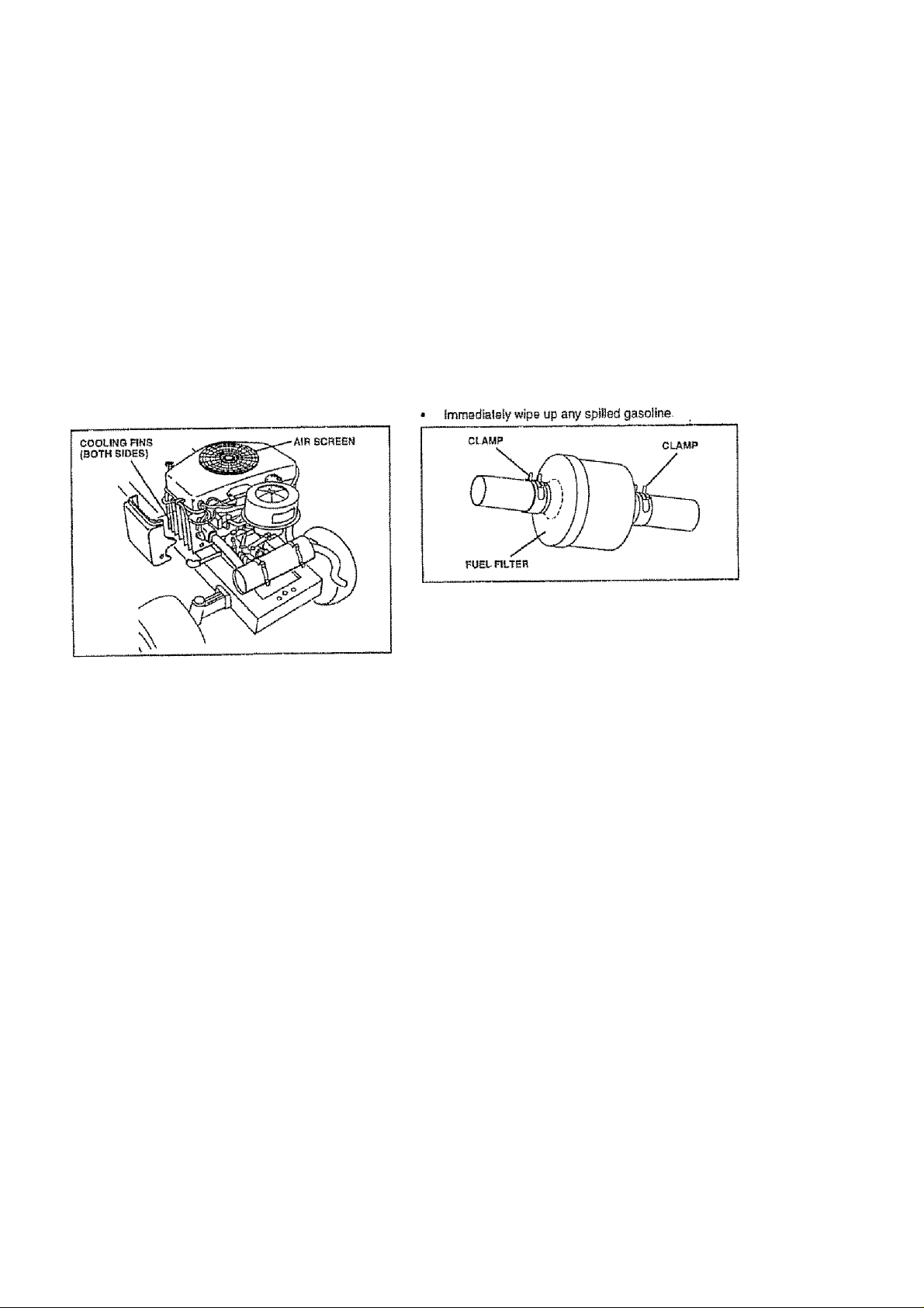
CLEAN AIR SCREEN (See Fig. 18)
Air screen must be kept free of dirl and chaff lo_ prevent
engine damage (rorn overheating Clean with a wire brush
or compressed air to remove dirt and stubborn dried gum
fibers.
ENGINE COOLING FINS (See Fig. 18)
Remove any dust, dirt or oil from engine cooilng lins to
prevent engine damage from overheating. Engine blower
housing must be removed. Remove side panels and hood
{See *TO REMOVE HOOD AND GRiLL ASSEMBLY"in the
Service and Adjustments section of this manual)
F)G..ia
ENGINE OIL FILTER
Replace the engine oil iiiter every season or every other oil
change II the tractor is used more than 100 hours in one
year,
MUFFLER
inspect and replace corroded muffler and spark arrester (if
equipped) as It could create a lire hazard and/or damage
IN-LINE FUEL FILTER (See Fig. 19)
The fuei filter should be replaced once each season. If fuel
filter becomes ologgad, obstructing fuel flow to carburetor,
replacemetit Is required.
• \¥iih engine coo!, remove filter artd plug fuel line
sactlona
• Place new fuei filter In position In fuel fine with arrow
pointing towards carburetor.
• Ba sura thera are no fuel line leaks and clamps are
properly positioned.
FiG. 19
CLEANING
• Clean engine, battery, seat, finish, etc of all foreign
matier
• Keep finished surfaces and wheels free of all gasoline,
oil, stcl
• Protect painted surfaces with aulomotfve type wax.
We do not recommend using a garden hose to clean your
tractor uniess the eiectrical system, muffler, air filter and
carburetor are covered to keep water out. Water In engine
cart result 1n a shortened artgine life.
SPARK PLUGS
Replace spark plugs al the beginning of each mowing
season or after every 100 hours of operation, whichever
occurs first Spark plug type and gap setting are shown In
"PRODUCT SPECIFICATIONS" on page 3 of this manual
20
Page 21

SERVICE AND ADJUSTMENTS
CAUTION: BEFORE PERFORWIING ANY SERVICE OR ADJUSTMENTS:
• Depress cluteh/brake psdal fully and set parking brake.
• Place motion control lever In neutral (N) position.
A
TRACTOR
REMOVE MOWER (See rig. 20)
» Place attachmeni clutch in "DISENGAGED” posltlon» Turn height adjustment Knob lo lowest setlJng.
» Lower mower to fls lowest posiiion.
• Remove retainer spring holding artli-swaybar to chas
sis bracket and disengage anti-swaybarfram bracket.
« Reraovs retainer springs Irom suspension arms at
deck and disengage arms from deck
« Raise attachment Kfl to its highest position.
• Remove two retainer springs irom each front link and
remove links.
• Slide mower forward and remove belt from electric
clutch pulley-
• Slide mower out from under right side of tractor,
IMPORTANT: )F AM ATTACHMENT OTHER THAN THE
¡MOWER DECK tS TO BE MOUNTED ON THE TRACTOR,
REMOVE THE FRONT LINKS.
INSTALL MOWER
W
Follow procedure described in "INSTALL MOWER AND
DRIVE BELT' In the Assembly section of this manual
• Place attachment clutch in “DISENGAGED" position,
• Turn ignition key "OFF” and remove key.
• Make sure the blades and ail moving parts have completely stopped.
• Disconnect spark plug wire from spark plug and place wire where It cannot come in contact
with plug.
ADJUSTMENT
TO LEVEL MOWER HOUSING
Adjust the mower while tractor is parked on level ground or
driveway. Make sure tires are properly inflated (See
"PROOUCTSPeC!F1CATIOIMS”cri page 3 of this manual).
If tires are over or undorinflated, you w! II not properly adjust
your mower
SIDE-TO-SIDE ADJUSTMENT iSse Figs, 21 and 22)
• Raise mower to its highest postiion-
• At the midpolnf of both sides oi mowe r, measure height
from bottom edge of mower to ground 0 istance "A" on
both sides ol mowaf should be Ihe same or within 1/4“
of each other,
• If adjustment Is necessary, make adjustmant on one
side of mower only.
« To raise one side of mower, lighten tilt link adjustment
nul on that side.
• To lower one side of mower, loosen lilt link adjustment
nul on lhal side.
NOTE; Each full turn of adjustment nut will change mower
height about 1/0"
• flacheck measurements after adjusting,
21
Page 22

SERVICE AND ADJUSTMENTS
FBONT-TO-BACK ADJUSTMENT (See Figs 23 and 24)
tivlFORTANT: DECK MUST BE LEVEL SIDE*TO-S!DE. !F
THE FOLLOWING FFtONT-TO-BACK ADJUSTMENT IS
NECESSARY, BESURE TO ADJUST BOTH FRONTUNKS
EQUALLY SO MOWER WILL STAY LEVEL SiDE-TO-
SIDE
To obtain the best culling results, the mower housing
should be adjusted so that the front Is approximately 1 /8“ to
1/2” tower than the rear whan the mower Is In its highest
position.
Check adjustment on right side of tractor- Measure dislarsce “D" directly in front and behind the mandrel at bottom
edge of mower housing as shown
• Before making any necessary adjustments, check that
both front links are equal in length Both links should be
approximalety 10-3/6".
• if links are not egual in ierigth, adjust one link to same
length as other iink,
» To tower front of mower loosen nut "E” on both front
links art equal number of turns
• When distance "D" is 1/6“ to 1/2" lower at front than
rear, lighten nuis "F' against tFunntoh on both front
links.
‘ To raise front of mower, loosen nut "F'lromlrunnioft on
both front finks. Tighten nut “E" on both front links an
equal number ol turns,
• When distance ”D" Is 1/B" to 1/2" lower at froM thari'
rear, tighten nut "F" against trunnion on both front links.
• Reoheck side-to-side adjustment.
MOWiR DRIVE BELT REMOVAL (See Fig. 25)
' Park tractor on a ievel surface Engage parking brake.
• Remove four screws from L,H mandrel cover and
remove cover.
• Roll bait over the top of LH. mandre! putey.
• Remove belt Irom eieciric clutch pulley.
• Remove belt from Idler pulleys.
• Remove any dirt or grass dippings which may have
accumulated around mandrels and entire upper deck
surface,
• Check primary idler arm and two Idlers to see that they
rotate treeiy.
• Be sure spring Is securely hooked to primary tdier arm
and boll in mower housing.
MOWER DRIVE BELT INSTALUTION (See Fig. 25)
• Install belt in both idlers. Make sure belt is in both belt
keepers at the idlers as shown,
• Install new bait onto electric clutch puliey,
• Rol! belt into upper groove of LH mandrel puliey
• Carefully check bell routing making sure belt is in the
grooves correctly and inside belt keepers
• Reassemble LH. mandrel cover.
Page 23

SERVICE AND ADJUSTMENTS
TO REPLACE MOWER BLADE DRIVE BELT
(See Fig. 26)
Park Ite tractor on level surface Engage parking brake.
Remove mowerdrJ ve belt (See ‘TO REPLACE MOWER
DRIVE BELT" In this section of this manual),
Remove mawer (See TO REMOVE MOWER" in this
section of this manual).
Remove four screws from R H, mandrel cover and
remove cover Unhook spring from bolt on mower
housing,
Carefully roll belt off R,H, mandrel pulley.
Remove belt from center mandrel pulley, idler pulley,
and L.H. mandrel pulley
Remove any dirt or grass which may have accumuiated around mandrels and entire upper deck surface.
Check secondary idler arm and Idler fo see that they
rotate freely.
Be sure spring is hooked in secondary Idler arm and
sway-bar bracket
Install newbeJt in lower groove of L.H, mandrel pulley,
Idler puliey, and cenler mandrel puiley as shown
Roil belt over R..H, mandrel pulley Make sure belt Is In
all grooves properly
Reconnect spring to bolt in mower housing and relnstatl R H - martdre! cover,
Reinstall mower to tractor (See "INSTALL MOWER
AND DRIVE BELT' in the Assambly section of this
manual). .
Reassemble mower drive belt (See "TO REPLACE
MOWER OfliVE BELT in this section Of this manual).
TO ADJUST BRAKE (See Fig. 28)
Your tractor is equipped with an adjustable brake system
which is mounted on the side of the iransaxie,
!f tractor requires mors than six (6) feet stopping distance
athigh speed in highest gear, then brake must be adjusted
• Depress clutch/braks pedal and engage parking brake.
• Measure distance between brake operating arm and
not “A" 0(1 brake rod.
• I f distance Is other than 1 -3/4”, loosen jam nut and turn
nut "A“ until distance becomes 1-3/4" Retighten jam
nut against nut "A".
• Road test tractor fo rproper stopping distance as stated
above. Readjust it necessary. If stopping distance is
still greater than six (6) (eel In highest gear, further
maintenance is necessary. Contact your nearest au
thorized service center/departmenl.
WITH PARKIMe BRAKS "ENGAGED"
NUT ‘ A‘‘
JAM NUT
TO ADJUST ATTACHMENT CLUTCH (See
Fig. 27)
The electric clutch should provide years of service. The
clutch has a built-in brake that stops the pulley within 5
seconds. Eventually, the internal brake will wear which
may cause the mower blades to not engage, or, to not stop
as required, Adjusiments should be made by your nearest
authorized service center/department
• Make sure attachment dutch and ignition switches are
in "OFF position,
• Adjust the three nylon locknuts until space between
clutch plate and rotor measures ,012“ at all three slot
locations
NOTE: Affsr installing a new electric clutch, run tractor at
full throttle and engage and disengage eteclrtc dutch 10
cycles to wear In dutch plats,
cut in the side of brake plate.
23
DO NOT TOUCH THtS NUT Г FOHTMEB SRAKE ADJUST
MENT tS NECESSARY CONTACT YOUR NEAREST AUTHO
RIZED SERVICE GEHTEFmEPARTMENT
FIG, 28
TO REPLACE MOTION DRIVE BELT
(See Fig. 29)
Park the tractor on level surface Engage parking brake
For assistance, there Is a belt installation guida decal on
bottom side of left footrest
• Remove trtower (See ‘TO REMOVE MOWER" in this
section of this manual )
• Disconnect dutch wire harness
• Remove dutch locator.
• Remove upper belt keeper.
• Remove bail from stationary idier and ciutching Idiar.
• Puli bait slack toward rear of tractor. Carefully remove
belt upwards from transmission input puiley and over
cooling fan blades
• Pull belt toward frontof tractor and remove downwards
from around electric clutch
• Install new belt by reversing above procedura
Page 24

SERVICE AND ADJUSTMENTS
IMPORTANT: MAKE SURE UPPER BELT KEEPER !S
POS!T!ONED PROPERLY BETWEEN LOCATOR TABS
and elec tric clu tc h w ire CONNECTION IS
SECURE.
ELECTRIC.
CLUTCH
yppER BELT
KEEPER
LOCATOR ■"
TABS
CLUTCHING
IDLER
STATIONARY
idler
TRANSMIBSIOK
INPUT PULLEY
_________________
CLUTCH LOCATOR
Fia 29
TO ADJUST MOTION CONTROL LEVER (See
Fig, 30)
The motion control Isver has been preset a1 the factory and
adjustment should not be necessary,
If for any reason the mofion control (svsr will nol hold Hs
position while at a seiecled speed, It may be adjusted at the
friction pack located on the right side of transmission.
• Park iraclor on level surface. Slop tractor by turning
ignition key to "OFF" position, and engage parking
brake.
• Adjust motion control lever by ttghtining adjustment
locknut one halt {1/2} turn
NOTE: If for any reason the eiforl to move the motion
control lever becomes loo excessive, reverse the above
adjustment procedure by loosening locknut 1/4 to 1/2 turn.
Road test tractor after adjustment and repeat procedure If
necessary
TRANSMISSION REMOVAL/REPLACEMENT
Should your transmission require removal for service or
replacement. It should be purged after relnsiaHallon and
betöre operating the tractor. See "PURGE TRANSMIS
SION" in the Operation section of this manual.
TO ADJUST STEERING WHEEL ALIGNMENT
II steering wheel crossbars are not horizorrtal (ieft to right)
when wheels ars positioned straightforward, remove steer
ing wheel and reassembte per instructions in the Assembly
section of this manual 24
FRONT WHEEL TOE-IN/CAMBER
The front Wheel toedn and camber are not adjustable on
your tractor. If damaga has occurred to affect the front
wheel toe-in or camber, contact your nearest authorized
service centsr/ctepailment.
TO REMOVE WHEEL FOR REPAIRS
(See Fig. 31)
• Block up axle securely.
• Remove axle cover, retaining rtng and washers to allow
wheel removal (rear wheel contains a square key - Do
not lose).
• Repair tire and reassembte,
• On rear wheels only: alion grooves in rear wheel hub
and axle, insert square Lay.
■ ReplacB washers and snap rstaihing ring securely In
axle groove
* Replace axle cover,
NOTE: To seal tire punctures and praverjt flat liras due to
slow teaks, tire sealant may be purchased from your local
parts dealer Tire sealant also prevents lire dry rot and
corrosion.
SQUARE KEY
(BEAR WHEEL OtTLY)
FIG. 31
TO START ENGINE WITH A WEAK BATTERY
(See Fig. 32)
CAUnON: Lead-acid batteries gener
ateexplosive gases. Keep sparks, flame
and smoking materials away from bat
teries. Always wear eye protection
when around betlerles.
If your battery Is too weak to start the engirre, it should be
recharged. (I “jumper cables" are used for emergency
starting, loHow this procedure:
ItytPORTANT: YOUR TRACTOR IS EQUIPPED WITH A 12
VOLT NEGATIVE GROUNDED SYSTEM THE OTHER
VEHICLE MUST ALSO BE A 12 VOLT NEGATIVE
grounded system, do not use your tractor
BATTERY TO START OTHER VEHICLES,
TO ATTACH JUMPER CABLES -
• Connect each end of the RED cable to the POStTiVE
(.{■) terminal of each battery, taking cars not to short
against chassis,
• Connect one end of tha BLACK cable to the NEGA
TIVE {-) terminal of fully charged battery
• Connect the other end of the BLACK cable to good
CHASSIS GROUND, away from (usi tankand battery
TO REMOVE CABLES, REVERSE ORDER -
• BLACK cable first from chassis and then trom tha tutly
charged battery
• RED cable last from both batteries
Page 25

SERVICE AND ADJUSTMENTS
œ
"POSITIVE“
C+)
FIG. 32
TO REPLACE HEADLIGHT BULB
• Raise hood-
• Puil bulb bolder out of the hole In the backside of the
grill. '
• Replace bulb Irt holder and push bulb holder securely
back into the hole In the backside of the grll)
» Close hQod
INTERLOCKS AND RELAYS
Loose or darnaged wiring may causa your tractor to run
poorly, stop running, or prevent it from starting,
• Check wiring. See electrical wiring diagram In the
Repair Parts section o( this manual-
TO REPLACE FUSE
Replace with 30 amp automotive-type plug-tn fuse. The
fuse holder Is located behind the dash-
TO REMOVE HOOD AND GRJLL ASSEMBLY
(See Fig. 33)
• Raise hood
• Unsnap headlight wire connector
• Stand in front of tractor. Grasphoodatsides,tilttoward
engine and lift off of tractor.
FIG. 33
ENGINE
TO ADJUST THROTTLE CONTROL CABLE
(See Figs. 34 & 35)
The throttle control has been preset at the factory and
adjustment should not be necessary Check adjustment as
described below before loosening cable. If adjustment Is
necessary, proceed as follows:
"NEQATiVE*
(■)
25
With enpfne not running, move throttle control ieusr to
fast posfllDrt.
Check that speed control lever is against slop screw. If
It is not, loosen casing clamp screw and pull Ihrottle
cable until iever !s against screw, Tighten damp screw
securely
STOP ECSEW
FIG.
3S
SPEED CONThOt,
yi* LEVER
TO ADJUST CARBURETOR (See Fig. 36)
The carburetor has been present at the factory and adjustmant should not be necessary However, minor adjostmenl
may be required to compensate for differences In fuel,
temperatura, altitude or load, if the carburetor doss need
adjustment, proceed as follows;
In general, turning the adjusting needles In (clockwise)
decreases Ihs supply of fuel to the engine giving a leaner
fuel/alr mijsture. Turning ¡he adjusfing needles out (coun
terclockwise) increases the supply of fuel to the engine
giving a richer fuel/alr mixture
liWPORTANT: DAMAGE TO THE NEEDLES AND THE
SEATS IN CARBURETOR MAY RESULT IF SCREW IS
TURNED IN TOO TIGHT
PRELIMINARY SETTINQ -
• Be sure you have a clean air filter, and the Ihroliie
conlrol cable is adjusted properly (see above),
• With engine off turn Idle fust adjusting needle In (dock-
wise) dosing It linger tight and then turn out:(coufilerdockwise) 1-1/4 turns
• Turn main fuel adjusting rreedle in folockwise) closing
finger light and then turn out (counterclockwise) 1 turn
Page 26

SERVICE AND ADJUSTMENTS
FINAL SETTING -
• Start engine and allow to warm lor five minutes. Make
final adjuBiments with engine running and shifi/motlon
conlrot lever in neirtrai (N) position.
• Withthrotilecontroilevertnlastposltion, turn main tue!
adjusting needle in (clockwise) unfit engine begins to
die then turn out (counterclockwise) urtiit engine runs
rough. Turn needle to a point midway between Ihoas
two positions,
• Idle speed seilina - With throttle control isvar in slow
position, engine should idle at 1400 RPM, If engine
¡dies too slow or fast, turn idie speed adjusting screw in
or out until correct Idle Is atlainad
• Idle fuel needie Betfino - With throttle control lever In
stow position, lurrt idle fuel adjusting needle In (clock
wise) until engine begins to die and then turn out
(Gountarclookwise) u nfii engine runs roug h. Turn needle
to a point midway between those two positions
• Recheck Idle speed Raacijust if necessary,
ACCElERATtON TEST -
• Move throllle control lever from slow to fast position. I!
engine hesitates or dies, turn idle mixture screw out
(counterclockwise) 1/0 turn. Repeat test and continue
to adjust, if necessary, until engine acoeierates
smoothly.
High speed stop Is factory adjusted. Do not adjust-damage
may result.
tMPORTANT: NEVER TAMPER WITH THE ENGINE
GOVERNOR, WHICH IS FACTORY SET FOR PROPER
EHGINESPEED, OVERSPEEDiNOTHE ENSiNE ABOVE
THE FACTORY HIGH SPEED SETTiNG CAN BE
DANGEROUS. IF YOU THINK THE ENGINE-GOVERNED
HIGH SPEED NEEDS ADJUSTING, CONTACT YOUR
NEAREST AUTHOFUZED SERVICE CENTER/
DEPARTMENT, WHSCH HAS PROPER EQUIPMENT AND
EkPEBieNCE TO MAKE ANY NECESSARY
ADJUSTMENTS. ‘
Page 27

STORAGE
Immediately prepare your tractor for storage at the end of
the season or if the tractor will not be used for 30 days or
more
CAUTION; Never Store the tractor with
pssoiine in the tank (nsWe a building
where fumes may reach an open flame
A
TRACTOR
Remove mower from tractor tor winter storage When
mower is to be stored for a period of time, clean it thor
oughly, remove alt dirt, grease, leaves, etc Store in a
dean, dry area.
• Clean entire tractor (Se e “CLEANING" In the Customer
• inspect and replace bells, if necessary (See belt re
• Lubricate as shown In the Customer Responsibilities
* Be sure that all nuts, bolls and screws are securely
• Touch up all rusted or chipped paint surfaces; sand
BATT'ERY
• Fully charge the battery tor storage-
• After a period ol time In storage, battery may require
• To help prevent corrosion and power leakage during
tomer Responsibilities section o! this manual)
After cleaning, leave cables disconnected and place
cables where they cannot come in contact with battery
terminals.
Be sure baltery drain tube Is securely attached.
If baltery Is removed from tractor for storage, do not
store battery directly on carrcrete or damp surfaces,
or spark. Allow the engine to coot
before storing In any enclosure.
Responsibilities section of this manual).
placement Instructions in the Service and Adjuslmenfs
section of this manual),
section of this manual
fastened, inspect moving parts for damage, breakage
and wear. Replace If necessary.
lightly before painting
recharging '
CLEAN BATTERY AND TERMINALS" in the Cus
FUEL SYSTEM
IMPORTANT: IT iS IMPORTANT TO PREVENT GUM
oePOSITS FROM FORMING IN ESSENTIAL FUEL
SYSTEM PARTS SUCH AS CARBURETOR, FUEL FILTER,
FUEL HOSE, OH TANK DURING STORAGE. ALSO,
EXPEmENGE INDICATES THAT ALCOHOL BLENDED
FUELS (CALLED GASOHOL OR USING ETHANOL OR
METHANOL) GAM ATTRACT MOISTURE WHICH LEADS
TO SEPARATION AND FOHMATtON OF ACIDS DURING
STORAGE. ACÍ0IC GAS CAN DAMAGE THE FUEL
SYSTEM OF AN ENGINE WHILE IN STORAGE
• Orate the fuel tank
• Start the engine and let it run until the fuel lines and
carburetor are empty
• Never use engine oroarfauretor cleaner products In the
fuel lank or permanent damage may occur.
• Use fresh fuel next season
NOTE: Fuel stabilizer Is an acceptable aliernativs in
mintmlzteg the iormatlon of fuel gum deposits during stor
age, Add Stabilizer to gasoline m fuel lank or storage
container, Always tollow the mix ratio found on stabilizer
container. Run engine at least 10 minutes after addirtg
slabllfzerto allow the stabizerto reach the carburetor. Do
not drain the gas tank and oarburetor if using fuel stabilizer.
ENGINE OIL
Drain oil (with engine warm) end replace with clean engine
oil- (Sea “ENGINE” In the Customer Responsibilities
section of this manual)
r'Vi IfvInl^DC
Remove spark plug(s)
Pour one ounce of oil through spark plug hole(s) into
cyiindsr(s|.
Turn ignition key to "START" position (ora few seconds
to distribute oil
Replace with new spark plug(s)
OTHER
Do not store gasoline from one season to another
Replace your gasoline can II your can starts to rusl
Rus! and/or dirt in your gasoline wilt cause problems
If possible, store your tractor indoors and cover it to
give protection irorn dust and dirt.
Cover your tractor with a suitable protective cover that
does not retain moisture. Do not use plastic, Plastic
cannot breathe which allows condensation to torm and
will cause your tractor to rust
IMPORTANT: NEVER COVER TRACTOR WHILE ENGINE
AND EXHAUST AREAS ARE STILL WAHM,
27
Page 28

TROUBLESHOOTING POINTS
PROBLEM
WfH not start
Kofd 10 Btan
Engine wtH not turn over
CAUSE
! Out ol ftio!
E. Engine not 'CHOKSO* properly
3 Englna fteotieti
4 Bad spa rfe plug6 Dirty ftir fflior
6 Dirty ftrel filler
7 Water in (wel
8- Loose or dfifnagsd wiring
6 Carburetor out ot adjustment,
1G Engine valves out ol adjUBtnisnL
1 Dirty air liter
Z Bad spark plug
3 Weak Ol deBd baitsry
4 Dirty fuel filter
5. Slate or dirty fuel
B, Lodss or damaged wiring
7 Carburetor oui of adlwlmenl
&: Engine valves out of adjustmerit
1, ClutotiferakB podsi not depressed
E, Atlachmefttcittlchlssnoagisc!,
3- Week or dead ballery
4, Blown loss
B- Corroded battery terminate,,
5 Loose or dafnBBsd wiling
7. faulty Ignliton switch
8 Faully solenoid or Starter
5 faully oparslor presence switehfes)
CORRECTION
1, Fill fuel tank
2- Set TO START ENOINE' In Operation sactlofi,
3, Wall BBvaral minutes bafora aíiempilng to start
4, Repiso» spatk plug.
5, Ctsan/raptece air liter
5. Replace IubI filter
7 Orato tuel tank and earbufstor. reilH lank wtih frnsh
gasoline end raplace fuel tillBfa Chock ell wiring,
a Ses To Adjust Oartsurslor' In Servios AdjuslinaniB
secUon.
10, Contact an BUihortitad sbivIbb cmtor/depBrimenl
1 Claan/rapisce Bir ffltsr2 Rsplaea spark plug3 Reehatge or replace ballery
4,- HoplacB fuBi IWer.
5 Drain fuel tank and rsliii with Iresh gasoline
6, Chackallwlftog,
7 Sea To Ad|usl Csrtiuralo!' In Servies AdjUBlmante
ssclion.
8 Conlael an aulhoiiiad servioa uonlBr/dEpflilmofil
1 Depress clutoWbrake pedal
2 Disengage aitaciwiant cluich,
3 Becharge qr replace battery
4 Replaça fusa
5 Cisan battery ta tmtaals
5 Check all wiring
7 CiiBck/raplasa ignliton switch
6 ChSCktrsplacO soisnold or starter
S Conlael an aulhorizad sarvlce canter/daparlment.
Engine ctlnlia but wlii not I Weak or dead bMtety. t FiedhtfflB or replaes battery
sitart Z CoFiods</baitsry terfTifnals
Lob s o( pow er 1. Culling too much grass/loo fast,
Excoselee wlbrsllon
3, Loose Of damagsd wlflng4 - Faulty solanoid or starter,
2, Thtoilte in ‘CHOKE* posWon.
а, auiSd'Up of grass, Ibbvss and trash under mqwar
4, Otrty air fillet,
5 Lowoil tevet/rflriy oil,
б. FBUlty spark plug
7, Dirty lual ilHer
3 Stale or dirty iuel
9 Water In fuel
10, Spark plug wtra toosB
11 Otrty angina air ssfeervffna
12 Olrty/cloaged myliiar.
13, Loose or damsgaci wiring,
14 Carburetor out ol ariuslmenl
18 ErtgktB valves out oi adjustmant
t Worn, ben! or loos b blada
Z Bant blade mandrel.
3 Lcose/datnagBd pBrt(s)
2 Glean battery lermlnsls
3 Ohack all wiring
4 ChBcidreplaca solenoid or steitar
1 - Sfll in “Hlgher Cut" posUion/reducB speed.
2. Adjust Ihroltla comrcti
3 Clean underside ol mower housing
4, Ctaan/repla« oir filter
5, Check oil levat/changa oil
6, Ciaon and ragap or change spark plug
7, Raplace iuel filter
B Drain fuel lank and refill with Irosli gasoltee.
9 Drain fuel lank and carburetor. tbWI tank wUh trash
gasolina and reptaca fusi filter
10 Connect and lighten spark plug Wire
tl. ClBaitanginsnlf scraefi/fios.
12- ciBan/rspieca mufflsr
13 Chtek sH wiring,
14 Sbb To Adjust Caiburelor'" In SsivIsb Ad|us!rnen!s
SBClfon,
15 Contaos an aulhoitesd sorvlce ostîtsr/deparlmBnt
1 Rapte» blade Tighten blada bolt
2 Replace blade manrirel,
3 Tighten loose p»rt{s)- Replace dsmagsd parts
28
Page 29

TROUBLESHOOTING POINTS
problem CAUSE CORRECTION
Engine oonitnues to run
when operator leavee aent
with atlaehment clutch
ongagod
Poor out - uneven
Mower biadcs win not
rolalo
Poor grass dfscharga 1 Ertglne sps ed too slow
HcQdllghl(3) not working
^{f so equl^pped)
t Faulti« operatof'SeteSy presence conitol system.
■f Worn, bent or loose blacJe
2 Mower deck not tevat
3. iulMup ol grass, (saves- end trash under mower,
4 Bertl blade mandrel
5- Cfogged moyrar deck vent holes from buildup of
grass, leaves, and trash around mandfsis,,
1 Obstruolion 1(1 dutch mochanism
2 WornWaraaged mowet drive belt
3, FíOüen Idtsr pulley
4 proíerrbíada mandrel
2' Travel speed loa last,
3 Wet grass,
4 Mower declt not (ava!
5- Low/unoven Иге aSr pressure
e Worn, bant or loose blade.
7 Buildup of grass, laevaa and trash under tnawar
8 Mower drive bell worn
5 Blades Impíoperíy installed
to Improper blades usBdi 1 Clogged mower dadt vent hotos fiom buildup of
grass, leaves, and trash around mandrals
t Switch is 'OFF
2 Bulb(s) burnsd out
3 Faulty llghi switch,
4 Laos® Of damaged wiring,
5 Blown fuae-
1 Check wiring, swllches and oomiacUans if not
oorractsd, contact an authotfeed service oenter/
department.
1 Replace Wade TlgWen bifide bolt
2, Levai mov/er deck3- Ctsisn underalrJa of mower housing
4 Replaça btaefa msntfrei
5 Clean around mandrels to open van! holes
t Remove obstruction
a Ropioca mower drive belt3 Repiacrî idiar pulley,
4 Replace Wada mEndrsi
! Fiscs thfotlls conlfol In "FAST" position
a Shift to stowsr speed.
3, Allow grass to dry betoro mowing
4 Laval mowar deck
5 Check tires lorptoperalr pressure.
6, Replece/sharpen blade Tighten blade Bolt
7, Clean underside ol mawar housing
B ReplBce mower drive belt.
S Rainatali blades sharp edga down,
i 0 Replace with blades listed In Ws manuel
i 1 Clears around mandrels to open vem holes
1 Turn switch "ON",
2 Ropiace bulb(e),
3 Checfdreplace light switch,
4 Check wiring ond œrsfteotions
5 Rspiace fusa
Sattsrv will not charge 1 Bed baltery C0ll(s)
Less of drivo 1 Fraowheoi oorrttai in “diSEtigagad" position
Engine "baekfires"
When twnfng engine
»^OPP»
2 Poor cable eonnactlons.
3. Faulty regulator (If so enuippedl
4 Faulty alternator
2 Molten drive boil warn, dsmegsd, or broken,
3. Alf trapped In iransrtsisslors during ihlpmettt
or servicing
1 Engine thnrWe control not set at "SLOW”
position lor 30 seconds before slopping engine.
29
1 RopjBoe bftUary
2 Check/ctoan all connections
3, Replace regulator
4 Replace altensalor,.
1 Fiaos Iraswhael coniroi 1rs "engaged“ position
2 Raptaos motton drivs bell
3 Purge îtasiemîssicm
t Move Ihrottfe coniroi to "slow* prasltlon end alfow
to idle for 30 seconds batsra slopping engine
Page 30

SERVICE NOTES
30
Page 31

SCHEMATIC
TRACTOR - - MODEL NUMBER 917.258692
IGNtTiON SWITCH
POSITION
RltN/UOMT B + L
CIRCUIT
OFF
Q + M + L
RUN B L NOM^
START
L + S MOPE I
“MAKE” I
noS'e
AtY
YOUR TRACTOR !S
EQUIPPED WITH A SPECIAL
alternator system^
THE LISHTS ARE NOT
CONNECTED TO THE
BATTERY, BUT HAVE THEIR
OWN ELECTRICAL SOURCE
BECAUSE OF THIS, THE
BRIGHTNESS OF THE LIGHTS
WILL CHANGE WITH ENGINE
SPEED.' AT IDLE THE LIGHTS
WILL DIM. AS THE ENGINE IS
SPEEDED UP, THE LIGHTS
WILL BECOME THEIR BRIGHTEST.
RELAY
I WIRING INSULATED CLIPS
MOTE
NOTE: IF WIRING INSULATED
GUPS WERE REMOVED FOR
SERVICING OF UNIT, THEY
SHOULD BE REPLACED TO
I PROPERLY SECURE YOUR WIRING
NON’REMOVABLE
31
PTO SWITCH
POSSTIOH I CinCVIT
OFF . j c+s, a+H
ON
ic + F. 2 + £. A -f- D
CONNECTIONS
HEADLIGHTS
REMOVABLE
CONNECTIONS
Page 32

REPAIR PARTS
ELECTRICAL
TRACTOH ‘ “ MODEL NUMBER 917.258692
32
Page 33

repair parts
ELECTRICAL
TRACTOR - - MODEL NUMBER 917.2586Э2
KEY PART
НО.
NO.
144926
1
74760412
2
3 STD551025
STDS51125 Washer
4
STDS4102S Nut
é
7
7697J
В 7603J
9 109596X
10 145211
11 150109
145769
12
16 153BS4
STD55112S
19.
20
73350400
136S50
2122 41S2J
4799J
24
25 146148
108a24X
26
не 145491
160784 Switch, Plunger
29
140301
30
12421IX
31
141226
32
33 10931OX
40
100721
7111040Б
41
iO 7 wV40
42
145673
43
73640400
44
45 122B22X
50
154963
140405
51
52 141940
17490508
55
70 140427
109748X
81
NOTE: All component dimensions given In U S. Inches
1 inch = 35-4 mm
DESCRlFTiON
Ballery
Bolt, Hex 1/4-20 UNO хЭ/4
Washer
Tube, Plastic
Tray, Batiary
Clamp, Hass
Bolt, itr, Frt 1/4-20x7-5
Holddown Btr Dash
Nut, Push Nylon 1/4" Ballery
Switch Iniarlock Push-In
Washer, Lock
Nut. Hex, Jam 1/4-20 UNC
Harness, Llghl Socket W/41S2J
Bulb, Light
Cable Battery
Cable, Battery
Fuse
Cable, Ground
Switch, Ignition
Nut, Ignition
Cover, Ignition Switch
Key, Ignition
Harness, Ignition
Bolt Btk Fin- Hex 1/4-20 UNC x 1/2
Cover, Terminal
Solenoid
Nut, Keps BIk. Hex 1/4-20 UNC
Ammetar Rectangular 15 Amp
Switch PTO 3 Pot Red Delta
Ring Retainer PTO
Wire Loop
Screw Thdrol 5/16-18 X 1/2 TYT
Harness Engine Koh 1В TWN 15 AR
Relay Asm
33
Page 34

REPAIR PARTS
TRACTOR - . MODEL NUMBER 917.258692
CHASSIS AND ENCLOSURES
34
Page 35

REPAIR PARTS
TRACTOR
CHASSIS AND ENCLOSURES
KEY
NO.
1
2
3 17490612
6
7 1453S1
8 126471X
S
10
11
13
17
19 17521312
24 STDS23710
25 19131312
26
28
29 136374
30 140002X558
31
33 145244X558
34
35
38
38 139886
39 139687
44 140675
47
SO 137304
59 110436X
64
66 156281X012
71 73640400
86 136570X558
87
90 STD551025
100 105037X
114 145349
115
117
119
120
121 137269
122 137270
123
124 1S7107
125 74150412
140 158418
145 166524
147
NOTE: A[l component dimensions given In U S, inches
MODEL NUMBER 917.258692
PART
NO. DESCRIPTION
15953Q
140356 Drawbar
155923
145203 Dash, Plaslta
STD633710
145218
145217
136673X558
STD541437
136373X42B
137113
145243X558 Footrest, RH
STDS337Ö7 Bolt
108067X
105531X Nut, Push, Nylon
150272 Dash, Lower
136671X65B
121794X
144283
19092016
137271
1S7105
74760412
8022J
11nch = 25 4 mm
OhBssfs
Screw, Thdroi, 3/8-16 x 3/4 Type TT
Saddle
Shield Heat Kohler MV18
Clip, Fuel Lins
Bolt, Carriage 3/8-16 x 1
Panel, Dash, LH
Panel, Dash, RH
Hood Assembly
Screw Slid Hex Hd W/PÍ
Boll
Washer 13/32 x 13/16 x 12 Gauge
Nut
Grill
Lens, Bar, Clear
Fender
Bracket Assembly, Fender
Footrest, LH
Nut, Pal
Bracket Assembly, Pivot, LH
Bracket Assembly, Pivot, RH
Fender Strap
Rod, Support Hood
Bushing, Snap, Spit!
Plate. Dash
Nut
Panel Assembly, RH
Panel Assembly, LH
Washer 17/64
Strip Foam 18"
Bracket, Support, Dash
Cover, Access
Washer Serrated Disk 13/32 x 1
Washer 9/32 x 1-1/4 x 15 Ga
Rivet, Ratchet, Female
Washer, Nylon
Rivet, Rächet, Male
Bracke;, Weldment Pivot Hood, LH
Bracket, Weldment Pivot Hood, RH
Screw, Machine 1/4-20 x 3/4
Bracket Suspension Front
Rod Pivot Chassis/Hood
Bolt Hex Hd 1/4-20unc X 3/4
Plug Dash BIk 500 Día E Lilt
35
Page 36

pCpAID DARTC
I IIhmk t, i I •
drive
TRACTOR - - MODEL NUMBER 917.258692
38
Page 37

REPAIR PARTS
DRIVE
TRACTOR - - MODEL NUMBER 917,258692
KEY PART
NO.
NO.
1 150071 Tfansaxle Assembly
142431
2
3 14399S
8 141002
13714D
9
76020416
74490544 Bolt, Hex Fighd 5/16-13 Gr 5
15
16 73800500
126197X Washer 15/32x1-3/4x1/4
17
74780S1B
18
19 73800600 Locknut 3/8-16
20 150280
130554 Knob
21
145627 Rod, Brake .
22
23 137141
73350600 Nut, Hex Jam 3/6-16
24
25 1068a8X
19131316 Washer 13/32 x 13/16 x 16 Gauge
26
27
76020412
28 145204
29 124236X
130807
30
32 74760512
STD533107
33
34 155071 Shaft, Foot Pedal
35 120183X
19211616
36
37 1S72H
38 123674X Idler, Flat
74760644
39
4470J Spacer
40
41 154777 Keeper, Belt Idler
19131312 Washer 13/32 x 13/16 x 12 Gauge
42
43 19111012 Washer 11/32 x S/B x 12 Gauge
47
127783 Pulley, Idler
154804 Beilcrank, Asm Clutch
46
49 123a05X Retainer, Beit
74760624 Bolt, Hex 3/8-16 X 1-1/2
50
STD541437 Nut, Crowniock 3/8-16
51
■y O ¿a ÍÍ A fS A
04
/doaUouw Nut, Look Hex w/lns 5/16-1B
10571OX Link, Clutch
53
DBSCRIPTiON
Spring, Brake Return
Pulley, Transaxle
Rod, Shifter
Clutch, Electric! 63 140189 Pulley, Engine
Pin, Colter 1/8 X 1
Nut Lock HxW/lnaS/16-l8unc 69 142432 Screw
Bolt Fin Hex 3/8-16 UNC x 1 Qr. 5
Bolt, Hex 7/16-20x4-1/4
Bracket Assembly, Ciutch
Spring, Rod, Brake
Pin, Cotter 1/0 X 3/4
Rod, Brake, Park
Cap, Plunger
Bracket, Transaxle, L.H.
BotJ, Hex Hd 5/16-1 a UNC x 3/4 88 12000008 Ring, Klip
Bolt,Carriage 6/16-18x3/4
Bearing Nylon
Washer 21/32 x 1 x 16 Gauge
Pin,Roil3/16x 1
Bolt, Hex 3/8-16x2-3/4
KEY PART
NO. NO.
57
140294
59
140312 Retainer, Belt
61
17490512
62 88B3R Cover, Foot Pedal
65 STD551143
66 15477B
71
14015B
73 166347
74
121199X Spacer. Split
75 121749X Washer 25/32 x 1-1/4 x 1S Ga
76 12000001 E-Rtng
77 1235B3X
7B 12174BX
81 156046 Shaft asm Cross 20" tires 650
82 123782X Spring, Torsion
83 19171216 Washer 17/32 x 3/4 x 16 Gauge
84 140548
86 71208 Bushing, Rod, Steering
07 19212016 Washer 21/32 x 1-1/4 x 16 Gauge
89 151146 Console, 6 Speed
74780636 Bolt Fin Hex 5/16-18x2-1/4
91
747B0524
92
93 142564 Line Fuel Hydro 4"
94 140462 Fan, Hydro 7“
144643 Control Bypass Hydro 20” Tires
95
96
4497H
97 140469 Keeper Bolt Rh Hydro 0750.18/20'
73510600 Nut Keps Hex 3/8-16 UNC
98
100 19111216 Washer 11/32 x 3/4 x 16 Ga.
102 141322 Washer Bellville .501Dx 1,50D
73940800 Nut Hex dam Toplock 1/2-20 UNF
103
104 140156 Arm, Control Hydro
105 71070516
106 7476052Q
118 154774 Spacer Beilcrank
121 154419 Nyliner Cluichmg StI
DESCRIPTION
V-Belt, Drive
ScrewThdrol 3/8-16x3/4
Washer, Lock Hvy HIcf Spr 7/16
Keeper Belt Engine
Strap Torque Lh Hydro 18/20”T
Strap Torque Rh Hydro 18/20'T
Key Square
Washer 25/32 x 1-5/8 x 16 Ga
Hydro
Rod, Tie
Bolt Fin Hex 5/16-18 UNC x 1-1/2
Retainer Spring I'^Zinc/Cad
Screw Cap Hex 5/16x18x1
Boil F!n Hex 6/16-1B UNC x 1-1/4
37
Page 38

REPAIR PARTS
TRACTOR »- MODEL NUMBER 917.258692
STEERING ASSEWBLY
f.
-39
38
Page 39

REPAIR PARTS
STEERING ASSEMBLY
TRACTOR - - MODEL NUMBER 917.258692
FART
KEY
NO. DESCRIPTION
NO,
121472X
1
154427
2
156483
3
4 157473
5 6266H
121748X
B
7
19272016
12000028 Ring, Klip
8
3366B Bearing
S
10
15643&
STDS51137
11
73940800 Nui, Hex. Jam Toplock 1/2-20 UNF
12
164779
13
15 73901000
156643
17
18 57079
19 124035X Supporl, Shaft
126684X
20
22
71200410
23 127S01
154406
25
27 136874 Gear, Sector
17490612
29
139929
32
33 1S111216
STD551131
34
73810500
35
36 145207
1S2927
37
186805X
38
100712K
39
STD541S37
40
41 100711L
42 140216
43
121749X
46 121232X
47 6855M
63 736B0600
1S65SS
62
05 1547B0
154404
66
67 74781044
154429 Brace Axle
68
160367
69
70 747B0636
NOTE: All companent dimensions given In U S, inches
1 Inch = 25 4 mm
S leering Wheel
Axle Assembly, Front
Spindle Assembly, LH
Spindle Assembly, RH
Bearing, Race, Thrusl, Hardened
Washer 25/32 x 1-5/8 X 16 Gauge
Washer 27/32 x 1-1/4 x 16 Gauge
Link, Drag
Washer, Lock
Bearing, Axle
Locknut, Hex, Jam, w/Washer Insert
5/8-11 UNO
Shaft Assembly, Sieering
Washer, Thrust 515 x ,750 X 033
Washer, Shim 1/4 x 5/8 X 062
Screw Hex Socket 1/4-20 x 2-3/4
Shaft Assembly, Pittman
Bracket, Steering
Screw, Thdroi 3/6-16 x 3/4
Tie Rod
Washer 11/32x3/4x 16 Ga.
Washer Lock Hvy Hltal Spr 5/16
Locknut 5/16-24 UNF
Bushing, Steering
ScrewTT #10-32 5 3/8 Flange
Inserl, Cap, Steering Wheel
Washer ,53 x 2.25 x .160
Nut Lock Center 3/8-24 UNF
Adapter, Steering Wheel
Column, Steering
Washer 25/32 x 1-1/4 X 16 Gauge
Cap, Spindle
Fitting, Grease
Nut, Crowntock 3/8-16 UNO
Kit, Steering Assembly
Spacer Axle
Searing Arm Pittman
Bolt Fin Hex 5/8-11 UNC x 2-3/4
Spacer, Brace Axle
Bolt, Fin Hex 3/8-16 UNC x 2-1/4
39
Page 40

REPAIR PARTS
ENGINE
TRACTOR - - MODEL NUMBER 917.258692
40
Page 41

repair parts
ENGINE
TRACTOR - - MODEL NUMBER 917.258692
KEY PART
NO, NO.
132755 Control, Throltie
1
2 17720410 Screw, Hex Head, Thread Cutting
3 Engine (See Breakdown) Kohler Model No
149783
5 130215 TutjB Manlloid LH Kohler MV1В
6 136216
130129
7
150176 Bolt 5/16-18 UNC X 3/4 w/Sems
a
156425
9
10 145332 Shield Heal
STD5S1131 Washer Lock Hvy HLCL Spr, S/16
11
74S70512
12
........
13
14
IS
16
17 17490624
20
23 156123
25 136672 Control Choke
26 73920600
29
31 151346
Э2
33 123407X Clamp, Hose
34 106062X Spacer, Pad
37 aS43R Line, Fuel
3B - - * - Plug, Oil Drain
39 109227X
40 3646J Bushing
41
ei
61 128661
8B
89 73800500 Nut, Lock Hex w/lns 5/16-16 UNC
90
91 71110408
SZ
93 123976X
NOTE: Al! companeni dimensions given in U.S inches
- * -
13280336 Nipple, Pipe
1Э200300
STD551237 Washer, Lock
156426 Shield Heal Browning RH
1371 BO
152334
17490612
139277 Stem, Fuel Tank
19111216 Washer 11/32x3Mx16Qa,
72110506 Bolt Rdhd Sank 5/16-18 UNC X 3/4
159520 Guard Debris
19091016
1 inch = 25,4 mm
DSSCRIPTfOlSl
1/4-20x578
MV18S-PS5856C!
Muffler, Asm. Twin Lo-Tone
Tube Manifold RH Kohler MV18
Clamp Tube Double Engine
Shield Heat Browning LH
Screw Hex Ski 5/16 UNV x 3/4
Gasket (Order From Engine Manufacturer)
Elbow. Standard 80", 3/8-18 NPT
Screw Thdrol 3/8-16 x 1-1/2 TT
Shield, Browning
NulKeps 3/0-24 UNF
Arrester, Spark
Tank, Fuel
Cap Assembly, Fuel
Screw Thdrol 5/16-1 a x 3/4 TYT
(Order From Engine Manufacturer)
Spacer Pad
Nut Flange 1/4-20 Starter Nu!
Bolt Blk Fin Hex 1/4-20 UNC x 1/2
Washc s/32x6/8x16Ga
Nut Lock 1/4 Lge F!g Gr. 5
41
Page 42

REPAIR PARTS
SEAT ASSEMBLY
TRACTOR - “ IVIODEL NUMBER 917.258692
KEY PART
NO. NO.
1 140123
2 1405S1
5 14500B
6 STD541437
7 124161X
10 155325
11 i20oeex
12 121246X
13 121246X
14 72050412
15 134300
DESCRIPTION
Seat
Bracks!, Pivot, Seat
Clip Pusfi'in
Nuif Lock Hex w/!ns. 3/B-1SUNG
Spring, Sea!
Pan, Seal
Knob, Seat
Bracket, SwHch Mounllng
Bushing, Snap, Nylon
Boll Carriage 1/4-20x1-1/2
Spacer, Split
KEY PART
NO. NO.
16 121250X Spring
17 123976X Nul, Flangetock 1/4 Grade 5
ia 124238X Cap, Spring, Seat
21 153236 Boii, ShoUWer 5/16-18 UNO - 2A
22 STD541431 Nut
24 19171912 Washer 17/32x1-3/16x12 Gauge
25 12701 ax Boll, Shoulder S/16-18 x .62
27 1749060B Screw Thdrol. 3/8-16 X 1/2
28 150176 Boll 5/16-18 X 3/4 w/Sems
NOTEi All component dimensions given In U S,, inchet
42
1 inch « 25 4 mm
DESCRIPTION
Page 43

REPAIR PARTS
TRACTOR « - MODEL NUMBER 917.258692
DECALS
KEY PART
NO. DESCRIPTION
NO.
166835 Decal, Operating Instruction
1
156707 Decal, Deck Mower. EZ3
2
3 160291
160292
4
151400 Decal, Grille 19
S
133544
6
138040 Decal, Side Panel 21 140837
7
142243 Decal, Side Panel 23
0
146709
9
10 158439
4flODJ Decal, Cluich/Brake
11
146046 Decal, V^Belt Drive Schematic
12
151401 Decal, Chassis, 46* Hydro Srs
13
Decal, Hood, Cratisman, RH 17
Decal, Hood, Craiisman, LH 18
Decal, Maintenance 20 149510
Decal, Fender, Craftsman 24 149918
Decal, Caution
Polo
KEY
NO. NO,
25 142341
PART
14 160397
15 1S0333
S2-113-S0
146710
138047
106202X
130311
. -
145246
145247
161000
1B1001
DESCRIPTION
Decal, v-Belt Schematic
Decal, Cap Cnsmr Help Una Srs.
Decal. HP Engine
Decal, insert SIrg
Decal, Battery
Decal, Btry, Dngr/Psn. Eng. Acme
Decal, Brake Parking Saddle
Reffecior, TsiHight
Decal. Fend Auto Trans
Decal, Drawbar Cnlri Mvt
Decal, Handle Lilt Height Actj
Pad Footrest
Fastener Pop-In Footrest
Manual, Owner's (Eng)
Manual, Owners {Span)
WHEELS & TIRES
KEY
PART
NO.
NO.
1 59192 Cap, Valve, Tire
2 65139 Stem, Valve
3 106222X Tire, Front
4 5BS04 Tube, Front (Service item Only)
5 106732X427 Rim Assembly, Front
6 278H Fitting, Grease {Front Wheel Only)
7 9040H Bearing, Flange {Front Wheel Only)
8 106108X427 Rim Assembly, Rear
9 122082X Tire, Rear
10 7152J Tube, Rear (Service I te m Only)
11 1047S7X Cap, Axle
-- 144334 Sealant, Tire (10 oz Tuba)
NOTE: Ail Component dimensions given In U S. inches
1 inch = 25.4 mm
description
43
Page 44

RERAiR PARTS
IVIOWEFi LIFT
TRACTOR - - MODEL NUMBER 917.258B92
44
Page 45

REPAIR PARTS
MOWER LIFT
TRACTOR - - MODEL NUMBER 917.258692
PART
KEY
NO.
NO.
159461
1
159476
2
1382B4
3
4 12000002
19211B21
5
6 120183X
125B31X
7
122365X BuHon, Plunger
8
139665
11
139BB6
12
STD62400B
13
15 127218
73350800
16
130171
17
73800800
18
139068
19
ST0624008
20
110807X
23
19131016
£4
1371 SO Sortnci"
25
76020300
26
27
137157
73350600
28
138057
29
150233
30
140302
31
73540600
32
15S0S7
36
37 123935X
38 17490512
19112410
40
123934X
41
49 145212
50 110452X
DESCRIPTION
Wire Asm.. Inner w/plunger
Shall Asm LIfi
Pin Groove
ERirro #5133-62
Washer 2l/32X1X21Ga
Bearing Nylon
Grip Handle Fluted
Link Lift Lh
Link Lift Rh
Retainer Spring
Link Front
Nut Jam Hex 1/2-13 Unc
Tfurmton BIk Zinc''
Nut Lock W/Wsh 1/2-13 Unc
Arm Suspension Rear
Spring Retainer
Nut Special
Washer 13/32 X 5/8 X 16 Ga
Pin Cotter 3/32 X1/2
Rod Adjust Lift
Nut Hex Jam 3/8-16 Unc
Knob infinite 3/0-16 Unc Black
Trunnion infin Height
Bearing Pvt Lift Spherical
Nut, Grownlock 3/8-24
Pointer, Height Indicator
Plug, Hole
Screw Thdro) 5/18*18 X 3/4
Washer 11/32 x 1-1/2 x 10 Gauge
Scale, Height Indicator
Nut Hex Flange Lock
Nut Push Phos & Oil
NOTE: All component dimensions given in U S inches
1 inch = 25.4 mm
45
Page 46

REPAIR PARTS
yOWER DECK
TRACTOR - - MODEL NUMBER 917.258692
Page 47

REPAIR PARTS
MOWER DECK
PART
KEY
NO.
NO.
156948
1
138457
3
STD624008
s
130832
6
B5Q857
8
STD55t137
S
140296
10
152443
11
129895
12
137553
13
137152
14
1104вВХ
15
140329
16
72140505
18
132827
1&
146055
20
STD541431
21
134753
22
131267
23
105304X
24
149267
25
11Q452X
26
1577S8
27
191Í101S
28
131491
29
30 157722
129963
31
153531
32
137266
33
144945
34
17490628
35
STD551037
36
131494
37
156086
3B
DESCRIPTION
Housing, Mowsr 46"
Bracket Asm., Sway Bar
Retainer Spring
Arm, Suspension, Rear {Sway Bar)
Boll. Patched 3/8-24 к 1-1/4 Gr. В
Washer, Lock Hsry., Unplated 3/8
Washer, Hard Blade, Mower
Vented
Blade, 46“ Mower Deck
Bearing, Ball, Mandrel #6204
Shalt Asm, w/Lower Bearing
(Includes Key No. 12)
Housing, Mandrel
Bearing, Sail, Mandrel
Stripper, Mowar Round
Boll, Carriage S/16-18 x 5/s
Boll, Hex Head, Shoulder S/16-18
Baffle, Vortex Mower 46"
Nut, Crownlock 5/16-1 BUNG
Slifflner, Bracket
Bracket, Deilectof
Gap, Sleeve
Spring, Torsion, Delleolor
Nut, Push
Shield, Deflector Mower
Washer 11/32 X 5/8 X 16 Ga
Rod, Hinge
Screw, Thd Rolling Washer Head
Washer, Spacer Mower Vented
Pulley, Mandrel
Nut, Rg Top Lock Cntr. 9/16
Anchor, Spring Deck 46"
Screw, Thdrof 3/3-16 x 1-3/4 Tytt
Washer 13/32 x 13/16 X 16 Ga.
Pulley, idler. Flat
Keeper, Belt, Idler
TRACTOR - - MODEL NUMBER 917.258692
PART
KEY
NO,
NO,
144917
39
40 137273
41 17490620
122062X
42
43 144949
133S43
14Б059
45
137729
46
47 14495Э
48 139573
STDS41437 Nut, Crownlock 3/8-16 UNC
49
72110612
50
1S3390 Washer Felt
51
166493
62
19131616
72
101 145579
71161010
102
10071000
103
19061216 Washer
104
160793
105
2029J Nut, Weld
105
137644
116
117 133957
73930600
118
119 19121414
125 144948
,j27
146763
158551
143651
- -
NOTE: Ail component dimensions given in U.S inches
1 inch = 25 4 mm
DESCRIPTION
Pulley, Idler, Driven
Spring, Secondary 44/46/50 Vant
Screw, Thdrotl 3/6-16x1-1/4 Tytt
Spacer, Retainer
Arm, Idler Secondary
Washer, Hardened
Cover, Mandrel Deck
Screw, Thdroll. 1/4-20x5/8
V-Belt, Mower, Secondary
V-Belt, Mower, Primary
Boil, Carriage 3/8-16 x 1-1/2 Gr S
Pulley Idler
Washer 13/32 x 1 X 16 Ga
Cover, MuJchlng
Screw
Washer, Lock #10
Lalch Asm, Bagger
Boll, Shoulder
Gauge Whsel, Wide
Nut, Centerlock 3/8-16 UNC
Washer 3/B x 7/8 X 14 Ga.
Atm, Idler, Primary Deck 46"
Pulley, Idler, V-Groove Dim. 4,25
Deck Complete (Std Deck-Order
separately muicner plate and gauge
whsel components Key Nos. 101
106 and 116-118J
Mandrel Assembly (Includes Key
Numbers 8-10,12-15, 31 and 33)
47
Page 48

REPAIR PARTS
TRACTOR - - MODEL NUMBER 917.258692
HYDRO TRANSAXLE - MODEL NUMBER 310-0650
34
X«K- 4-^ ^
^ 82 S3
'.^93 5Z
48
Page 49

REPAIR PARTS
TRACTOR - - MODEL NUMBER 917.258692
HYDRO TRANSAXLE - MODEL NUMBER 310-0650
KEY PART
NO. NO.
1 142930
142931
2
3 142932
4^
142928
142933 Ring. Reiaining
5
142934
6
142935
7
B 150771
142937 Swashplate, Variabie
9
14293B
13
142939
14
142940 Seal, Lip
15
142941
17
150772
ie
150773
19
23 142044
24 142945
25 142946
28 150774
142948
27
28
14294S
29 142950
30 160787
142951
34
3S 142952
142953
36
142954 Arm, Actuating
37
3839142055
150777
150778
40
142958
41
description
Housing, Lower
AsssmSly, Upper Housing
Seal, Lip
Ring, Vvira Retaining
Bearing, Shaft Bali
Bearing, Cradle
Bearing, Thrust 30 x 52 x 13
Biock, Cylinder Assembiy
Arm. Trunnion
Guide, Slot
Shalt, Motor
Bearing, Thrust 42 x 68 x 16
Block, Cylinder Assembly
Seal, Up 10x25x7
Actuator, Bypass
Center Section Assembly Kit
Seal, Up 26 X 42 X a
Ring, Retaining
Washer 26 x 35 x 1
Plate, Bypass
Oil Filter Element
Arm. Bypass
Ring, Retaining
Pin, Actuating
Bolt 5/16-24x1-3/4
Locknut, Hex S/16-24 UNJC
Brake Rotor/Stator Kit
KEY PART
NO- NO.
43 142684
44
150B29
142S91
52
53 142961
SG
142963
58 142B64 Bolt 1/4-20 X 1.38
69 142965
62 142966
63 142S67
64 142920
142969 Spring
68
09 144610
142971
83
65 150806 Jackshaft
08 142973
89 142974
BO 142975
142976 Seal. Wiper
91
142977
92
142978
93
142917
113
114 142918
142980 Spacer
119
134 144607
135 144608
150775 Spring, Compression
139
140 1S0776
NOTE: Al) component dimensions given in U.S. inches
1 inch= 25.4 mm
DESCRiPTtON
Washer 7/16 x 7/8 x <360
Differential Assembly
Washer 3/4 x 1.5 x .13
Sea) .76 X 1 2S X .250
Shaft, Input
Pin 5 nn X 43 in X 750
1 nl LJ Ww A "tCx IL* a ’ r Jv
Arm, Control
Puck, Dampener
Set Screw
Stud 6/16-24
Jackshaft Assembly
Screw, Cap
Washer 7hs x 1 x 1/2
Sleeve Bearing
Spring, Black
Washer, Block Thrust
Cap, Vent Assembly
Fitting, O-RIng Assembly
Not, Castle 5/16-24
Pin, Cotter
Nul, Hex 5/16-24
49
Page 50

repair parts
TRACTOR - - MODEL NUMBER 917.258692
KOHLER ENGINE - MODEL NUMBER MV18S, TYPE NUMBER PSB856Q
50
Page 51

REPAIR PARTS
TRACTOR - - MODEL NUMBER 917.258692
KOHLER ENGINE - MODEL NUMBER MV18S, TYPE NUMBER PS58560
Am INTAKE
KEY PART
NO. N0-
Ì X-Z7B~7
2 5Z"765-83
3 52-096-35
4 S2-123-21 Tubs,
5 S31032
6 52-082-04
7 45-083-01
a 45-083-02
g 237423
to x-er-sa
11 52-201-06
12 277093
13 52-034-39
14 X-25-79
15 X-SO-37
16 X-50-57
17 X-22-9
16 25-041-06
NOT ILLUSTRATED
-- 25-113-15
-- 52-113-30
DESCRIPTION
WIngNtil 1/4-20
Kil, Cover end Tube
(Includes Key Numbers 3 and 4)
Cower, Air Cleener
Air Intake
Seal* BemenI Cover
Covar, Air Cteenar Element
Pra-cteaner
Element
Seal, Air Cleaner Cover
Screw, Hex Washer Heed
1110-32x0/16(4)
Bass, Air Cleaner
Gasicel, Air Cleaner (2)
Elbow, Air intake
Washer, Plain й10
Screw, Stotled Pan Head
#10-32x2-1/4
Screw, Slotted Pan Head
#10-32X i-3/4(2)
Washer, lock, Interna! Tooth
#10(2)
Gaskel, Air CIsaner Elbow
Decal, Air Cleaner
Decal
BAFFLES & SHROUD
KEY PART
NO. NO,
52-083-41
1
52-313-OS
a
52-083-42
3
4 X-87-B3
52-755-70
5
52-217-01
6
52-466-16
7
S 52-006-11
52-124-23
0
NOT ILLUSTRATED
*. -
52-113-46
DESCRIPTION
Saflla, #2 Cylinder Head
Grommet (2)
Baflie, Fue! Pump
Screw, Hex Wasnar Head
1/4-20x7/16(14)
Kit, Btewer Housing
(Includes Key Numbers 6 Ihtu B)
Support, Upper Housing
Washer, Fiat {2}
Screw 1/4-20 x 5/0 (8)
Beffi«, #1 Cylinder Head
Decal, Horsepower (3)
BREATHER & VENT
PART
KEY
NO, NO,
1 X-81-1
K-25-12
2
S2-Q96-ia
3
52-055-01
4
X-352-39
S
52-328-12
6
52-098-08
7
52-032-04
8
g 52-462-01
52-096-22
10
275220
11
NOTE: AH component dimensions given In U S Inches
1 Inch 25 4 mm
DESCRIPTION
Hui. Hex 1/4-20(2)
Washer, Plain 1/4 (2)
Cover, #2 Cylittdar Veivs
Qasitel, Cover (3)
Stud, #S Cylinder Valve Cover
1/4-20x2-1/4
Hose, Breather
Cover, #1 Upper Cylinder Valve
Seal, Breather
VatvB, Umbrella
Cover, #1 Lower Gylindar Valve
Stud, #1 Cylinder Valve Cover
1/4-2DX 3-1/4
51
Page 52

REPAIR parts
TRACTOR - - MODEL NUMBER 917.258692
KOHLER ENGINE - MODEL NUMBER MV18S, TYPE NUMBER PSS8560
52
Page 53

REPAIR PARTS
TRACTOR “ “ MODEL NUMBER 917.258692
KOHLER ENGINE - MODEL NUMBER MV18S, TYPE NUMBER,PS58560
CRANKCASE
KEY PART
NO. NO.
1 X-B2-2
a S2-4BB-12
3 B2-755-16
62-016-05
4
5S-031-01
5
52-316-06
В
S2-7SS-50
7
52-072-12
a
25-QB6-12
9
X-269-43
10
52-078-05
11
52-030-10
12
52-030-11
52-030-12
25-086-10
13
14 25-006-13
15 52-141-02
16 52-139-08
17 25-086-11
18
52-032-10
82-755-17
19
30
DESCRIPTION
Nut, Hax 5/16-18 (12)
Washer, Fiat 5/16(12)
KH. #1 Gyilrsdet Barra!
ilncludes Kay Numbers 4 thru 6)
Valve, Exhaust
Inserì, Valva Sea! (2)
Guide, Valve |2)
Kit. 00 Reliel
Step Stud 5/16-18x3/4,
3/8-1S X 5/6, 2' Long (12)
Screw, Hex Flange S/16-18 x 2 (2)
Ring, Retaining
Shalt, Governar
Bearing, Sleeve, Standard (2)
Bearing, Sleeve .010’
Bearing, Sleeve .020'
Screw, Hex Flange
5/16-18 X 1-1/2 (3)
Screw. Hex Flange
3/8-16 X 3-5/S (2)
0-Bing
Plug
Screw, Hex Ftanfe
5/16-18x3-1/2(8)
Seal, Oil, Front
Kit, ^9 Cylinder Barrel
(IndutJas Kay Numbera 4 thru 6)
Crankcase (service with Short Block,
Pari Number 82 522 30)
CARBURETOR
KEY PART
NO. NO,
1 52-041-09
2 S2-755-91
S2-164-1S
X-2M
X-6-29
X-75-23
7 2Э577Э
a X-67-97
41-072-19
9
52-063-40
10
2S-1SS-02
11
ези'з oc
ui£“‘00»5*4££3
12
271030
13
52-053-54
14
25-041-06
15
X-77-2
16
232857
17
X-67-62
18
088- 27
19 as-
146-03
20 as
144-24
si 52
368-01
22 2S-
oaa-02
23 25
-OBS-26
24 as-
089- 04
25 25
■368-03
26 25
083-02
27 25
■OSO-13
га Ba
083-03
ss 25
■194-01
30 25-
■146-02
SI 25-
wt/Э rtK
041-04
iati ¿и*
•757-09
33 25
■104-01
34 25
•041-03
36 25
•100-05
36 25-
NOT ILLUSTRATED
-- 25-757-11
- - 25-767-23
NOTE; At! component dirnenaions given In U S inches
1 inch = 254 mm
DESCRIPTION
Gasket, intake (2)
Kit, Manilold
(includes Key Numbers 3 Ihru B)
Manlfoid, intake
Washer, Lock 5/16 (4)
Screw, Hex Cap 5/16-16 x 2 (4)
Plug, Hex, Countersunk
1/8N,P,T.F,
Clamp. Cable (2)
Screw, Hex Washer Head
fflO-24 X Ш (2)
Stud 5/16-18x1(2)
ВвШв, Carburetor
Connector, Hose
KH, Caiisuretorwith Gasket (Includes
Key Numbers 12 Ihru 14)
Gaskat, Carburetor (2)
Catburelar Assembly (Information Only
• No! Aveilabie Separately) (includes
Key Numbers 18 thru 35)
Gaskat, Air Cleaner
Nut 5/16 (2)
Slrap, Ufiing
Screw, Hex Washer Head
1/4-20x3/4
Screw. Throttle and Choke Ptals (4)
Plat®, Choke
Shaft, ThroiliB with Uvsr and Sea!
Needle. Idle Fuel Adjust
Sprirrg, Idle, Fuel
Screw, idle Speed Adjust
Spring, Idis Speed
Nsedie, Main Fuel
Spring, Main Fuel
Lever, Choke
Spring, Choke, Friction
Bali, Choke, Friction
Plata. ThmtiSe
Gasket, Bowl
KH. RoBt
Bowl, Fuel
Gasket. Bowl Helalnar Screvr
Screw, Bowl Retainer
Kit, Carburetor Repair
Kit, Bowl BbIHs
53
Page 54

REPAIR PARTS
TRACTOB - - MODEL NUMBER 917.258692
KOHLER ENGINE - MODEL NUMBER MV18S, TYPE NUMBER PS5B56Q
Page 55

REPAIR PARTS
TRACTOR - - MODEL NUMBER 917.258892
KOHLER ENGINE - MODEL NUMBER MV18S, TYPE NUMBER PS58560
CRANKSHAFT
KEY PART
N0- NO.
5E-ai4-S3
1
52-466-03
S
52-468-04
52-468-05
description
Crankshsit
Washer, Thrust 119/1S2 (A.R)
Washer, Thrust 126/131
Washer, Thrust .137/.140 (A R)
DIPSTICK
PART
KEY
NO
NO.
52-036-14 Dlpsltek Assembly
1
X-25-44 Washer, Plalrr 5/16
S
3 sa-032-14
41-153-01 O-Ring
4
62-186-11
S
S2-123-20 Tuba, Oil Fill 11-7/a
0
47-139-01
7
DESCRIPTION
(Includes Key Numbers 2 errd 3)
Seal, Rubber
Bracket, 01! Tube Support
Plug, Hax, Countersunk
3Mfi PT.F.
CYLINDER HEAD
PART DESCRIPTION
KEY
NO. NO.
1 S2"D4t-20
2 sa-ots-oe
3 220534
4 41-080*02
Gasket, Head ¡2}
Cyffnder Head (2)
Washer. Plain s/ie(10)
Screw, Hex Head
5/10-18x1-1/2(10)
i**t tgft'ip ISif^ C*“l* A t>4‘
KEY PART
NO.
1
a X-20-1
3 x-ei-t
4
S
9 S2-17D-05
7
8 52-227-10
9 82-756-28
NOT ILLUSTRATED
I w & I ^ ^ I Clfi
NO
52-098-1 a
82-755-26
52-031-07
52-211-01
aS-4 50-03
EXHAUST
PAfiT
KEY
NO. m-
1 SE"'126^ 12
X'"25'’72
2
3 62-086-11
4 52-041-14
NOTE: All comporreni dimensions given In U S inches
1 inch i! 25 4 mm
DFSCRIPTION
Starter Assembly
(Includes Kay Humbers 4 thru 9)
Washer, Lock 1/4 (2)
Nut, Hex 1/4-20 (2)
Kit, Drive
Cep, Drive End
Amialufs
Bolt, Thru (2)
Cap, Commulalof End
Kil, Brush
Tag, Caution
DESCRIPTION
Bracks!
Washer. Plain (3)
Screw 1/4-20 x S/S (3)
Gasket, Exhaust (2)
55.
Page 56

REPAIR PARTS
tractor ” - MODEL NUMBER 917.258B92
KOHLER ENGINE - MODEL NUMBER MV18S, TYPE NUMBER PS5S560
GOVERNOR
SGNITION
27
28
29
8
9s IB’-C- *
"1
O 22 V,
2s'^
V /'f vi' ”
2S
¡\
n
FUEL PUMP
24
ia
/.■
23
'20
FLYWHEEL
S
56
Page 57

REPAIR PARTS
TRACTOR - - MODEL NUMBER 917.2S8692
KOHLER ENGINE - MODEL NUMBER MVISS, TYPE NUMBER PSS8560
FLYWHEEL
KEY PART
NO. NO,
25-162-01
1
25-08S-21
2
3 25-112-04
2S-157-01
4
25-006-24
5
6 52-468-16
7 X-286-17
52-025-38
S
GOVERNOR
KEY PART
NO. NO,
23135S
1
X-25-12
2
3 237022
A-236743-S
4
62-078-04
S
X-25-102
5
7 х-абэ-на
X-2S-72
a
52-090-23
g
277341
w
52-158-07
11
25-0Э6-15
12
62-089-07
13
14 X-81-1
IS X-25-63
16 52-188*09
52-211-04
17
18 25-141-03
25-158-08
19
52-079-07
20
52-079-06
21
52-090-14
22
52-089-08
23
25-086-21
24
25 X-87-97
235778
26
27 25-431-01
28 X-70-3
2Э 52-086-05
DESCRIPTION
Screen, Grass
Screw, Hex Washer Hsad
1/4-20x5/8(4)
Spacer (4)
Fan
Screw, Hex MacWns 3/8-24x1-1/4
Washer, Plain
Key, Square 3/16 x 7/8
Flywheel
DESCRIPTION
Pin, Governor Slop
Washer, Plain 1/4
Washer, Thrust
Kit, Governor Gear
Shatl, Governor Cross
Washer, Plain 1/4 {2)
Relalner, Governor
Washer. Plain 1/4 (2)
Lever, Speed ConJro!
Washer, Tension
Bushing, Thfottte Control Lever
Screw, Hex Washer Heed
1/4-20 X 1
Spring, Governor
Nut, Hex 1/4-20
Washer, Plain 1/4
Arm, Governor
Screw, Round Head, Square Neck 1/
4*20 X 1
Ring, Retaifllfig (4)
Bushing, Linkage Relalning (4)
Linkage, Governor
Linkage, Throtlla
Lever, Thro! He
Spring. Torsion
Screw, Hex Washer Head
1/4-20x5/8
Screw, Hex Washer Head
»10-24x3/8(3)
Clamp, Gable {3}
Bushing, Speed Control Lever
Nui, Hex »10-32
Screw. Hex Head IHO-32 x 7/8
fuel pump
KEY PART
NO. NO.
47-086-08
1
52-559-01
a
3 x-aao-1
x-as-63
4
as-041-оэ
6
6 25-165-02
7 X-426-S
В 62-353-18
25-060*03
Э
15-353-04
10
description
Screw, Pozidriv, Truss Head
1/4-20x5/8 (2)
Pump, Fusi Assembly
(Includes Kw Numbers 3 thru 6)
Cofinector, Straight
Washer, Plain lA (2)
Gasket, f^usl Pump
Connector, Hose
Clamp, Hoae (4)
Una, Fuel, 8”
Fitiar, Fuel
Una, Fuel. 11-1/2"
IGNITION
PART
KEY
NO
NO.
t gS-755-03
X-132-5
a
236602
3
4 237878
5 X-87-51
6 210281
X-67-S4
7
8 41-155-03
220297
9
52-313-02
10
11 52-132-02
Sa-126-08
12
13 25-088-15
14 52-584-02
25-086-16
15
NOT ILLUSTRATED
. - 47-518-.33
S2-Sia-1S
NOTE: All comporrent dimensions giwan in U,S, inches
1 inch =254 mm
DESCRIPTION
Kf!, RsoUlisr-Regulalor
(Indudas Kay Number 2)
Screw, Hex Gap 1/4-20 x 5/8 (2|
Connector, 3 Contact
Kit, Slator (includes Key Numbers)
Screw, Hex Cap #10-24 x 3/4 (2)
Clip (2}
Screw, Hex Washer Head
#10-32x7/18
Cofineolor, 2 Contact
Grommet, Rubber
Grommet
Spark Plug (2)
flrackst, Module
Screw, Hex Washer Head
1/4-20 X1 (2|
Module, Ignition
Screw, Hex Washer Head
1/4-20 X 7/a (2)
Lead. Vtoiel, RectlHer-Regulator
i11", 14 Gauge, Uninsuleied Push On
TabTsrminafe) _ ,
Lead, White, Module To Connector
(19-1/2*', 14GausB, insulated Push On
Tab, UnlnsuialecTPush On Tab
Terminals)
57
Page 58

REPAIR PARTS
TRACTOR «- MODEL NUMBER 917.258692
KOHLER ENGINE - MODEL NUMBER MV1BS, TYPE NUMBER PS58560
58
Page 59

OCDAIP PAPT'<^
i ■IhmI I 1 «nitl 1 I
TRACTOR - - MODEL NUMBER 917.2S8692
KOHLER ENGIiiE - MODEL NUMBER MV18S, TYPE NUMBER PS58560
OSL PAN
KEY PART
NO. NO.
1 X-67-64
sa-050-03
52-139'14
X-702-14
52-054*07
х-7з-за
7 X-7S-10
a 52-088-12
9 52-032*10
OiL PILTER
KEY PART
NO. NO.
62-050-02
82-75S-23
X-55-15
X-75-23
52-041-ie
PISTON & ROD
KEY PART
NOi NO.
1 52'0e7-67
32-067-68
2 52-S74-11
52-074-12
52-874-13
52-874-14
52-874-15
3 230004
4 52-108-09
52-108-10
S2-10a-11
SS-108-12
DESCRIPTION
Scfaw, Hex Washer Head
#10-32x7716(2)
Fiftar, OtI Pickup'
Oil Pan (InclydBS Kay «4 thru 6)
Plug, Cup 1-1/16
Elbow, Streal
Plug, Hex, Countersunk
1/4N-P.TP.-
Plug, Square Head 3/8 N P T F (2)
Screw, Hex Waaher Head
5/16-18x1-1/4(9)
Seal, Oil, Rear
DESCRIPTION
Oil Filler
Kil, Oil Pilfer Adaptor
(includes Key Numbers 3 thm S)
Screw, Hex Sockst Head
5/16-18 X 1-1/4 (2)
Plug, Hex, Countersunk
1/6N.PT.F.
Gasket, Oil FHIer
DESCRtPTiON
Connecting Rod, Standard {2}
Connecting Hod .010" (2)
Piston with Ring Set. Standard (2}
Piston with Ring Set ООЗ" !2)
Piston with Ring Sst 010" (2)
Piston wilh Ring Set 020" (2'
Pision with Ring Set .030" (2',
Rsiainer. Piston Pin (4)
Ring Set, Standard and ООЗ" (2)
Ring Sat 010" (2)
Ring Sat -020" 2)
Ring Sat 030" (2)
LOW OIL PRESSORE SWITCH
KEY PART
NO NO,
1 X-75-23 Plug. Pipe 1/S N.P T.F.
DESCRIPTION
CAMSHAFT & VALVES
KEY
PART
NO.
NO.
1 S2-012-D9
a 52-019-03
3
41-755-10 Kit, Retainer (4)
4 52-413-01 Holalor, Exhaust Valve (2)
5 25-08Э-01 Spring, Valve (4)
6 52-016-05 Valve. Exhaust (2)
7 52-017-08 Vaive, Intake (2)
8
52-032-13
Э 230011
•
After serial no 24082000 use:
S2“012*11
1
2 52‘01S‘02 Tappst
OIL PUMP
KEY PART
NO. NO.
1 X-280-25
2
52-144-05
52-422-01
3
4 52043-05
c-0 <iO'a ЛС1
ÖÄ-JoO-Uy
5
В 52-096-03
X-67-64
7
DESCRIPTION
Caihshafi
Tappet (4)
Seal, intake Valve Stem (2)
Relalner, Intake Valve (2)
Camshaft
DESCRIPTION
Pin, Roll
Shall, Ql! Pump
Speoar, Shim
(As Required, Maximum oi 2)
Gear, Oil Pump
Rotor Set
Cover, Oil Pump
Screw, Hex Washer Head
«0 32x7/16(4)
NOT ILLUSTRATED
- - 82-522-30
- - S2-75S-94
RPM Settings;
NOTE; Ail component dimensions givers Irs U S irrches
1 Irsch = 25 4 mm
Short Slock
Gasket Sat
Low Speed: 1150-1650
High Speed: 3200-3400
59
Page 60

SERVICI NOTES
60
Page 61

SERVICE NOTES
61
Page 62

SERVICE NOTES
62
Page 63

SUGGESTED GUIDE FOR SIGHTING SLOPES FOR SAFE OPERATION
ONLY RIDE UP AND DOWN HILL,
NOT ACROSS HILL
out^
S«.al’i^L>^Vyt»WVVVVV\%VVVVVVWVWmv-tT.W-n,tn-taîv
vtvv»yvvwv>vmYYt»wmwv>vv>vtv>vm>^t'>wvmvvHTOvvvHrtwvw>vvvvmaa.ttVftmvHVYyw»wHv>vvvvvyy)-v»vvY>vw»vvvvvvvvv>v>Hffl
Operate your Tractor up and down the face of slopes (not
greater than 15“), never across the face. Make turns gradu
A
ally to prevent tipping or loss of control. Exercise extreme
caution when changing direction on slopes.
Page 64

CRRFTSMRN^
OWNER’S
MANUAL
IWIODEL NO
1 Vi^wr LiM Im
917.258692
IF YOU NEED
REPAIR SERVICE
OR PARTS;
FOR PEPAfR SERVtCE, CALL
THIS TOLL FREE NUMBER:
1-800-4-REPAIR
(1-S00.473-7247)
FOR REPLACEMENT PARTS
INFORMATtON AND
ordering; CALL THtS
TOLL FREE NUMBER:
1-800-FON-PART
(f-a00-36e-7278)
FOR CONSUMER ASSISTANCE
HOTLINE, CALL THIS
TOLL FREE NUMBER:
1-800-6S9-5917
18.0 HP
electric start
46” MOWER
automatic (HYDROSTATIC)
LAWN TRACTOR
Each traclor has Its own model number Each engine has
its own model number.
The mods! number tor your traclor will be found on the
model plate located under the seat.
The mode! number for your engine will be found on the
blower housing of the engine..
All parts listed herein may be ordered from any Sears,
Roebuck and Co Service Carrter/Department and most Re-
tail Stores
WHEN ORDERING REPAIR PARTS, ALWAYS GIVE THE
FOLLOWING INFORMATION:
. PRODUCT- TRACTOR
• MODEL NUMBER-917.25BB92
• ENGINE MODEL NO. - MV18S - PS5B560
* PART NUMBER
• PART DESCRIPTION
Your Sears merchandlsa has added value when you
Gonstder Sears has service units nallonwide staffed with
Sears trained technicians... professional technicians
specifically trained lo insure that we meet our pledge to
you, we service what we salt.
161000 6.2-97 JH
Sears, Roebuck and Co., Hoffman Estates, fL, 6D179 U.S.A.
Printed in U S.A
 Loading...