

Page 1
CRI FTZMnN
MODEL NUMBER 917.257630 OWNER'SMANUAL
- Assembly
, Operation
* Customer Responsibilities
* Service and Adjustments
Repair Parts
CAUTION: Read and follow all safety rules and instructions before operating this equipment.
Page 2
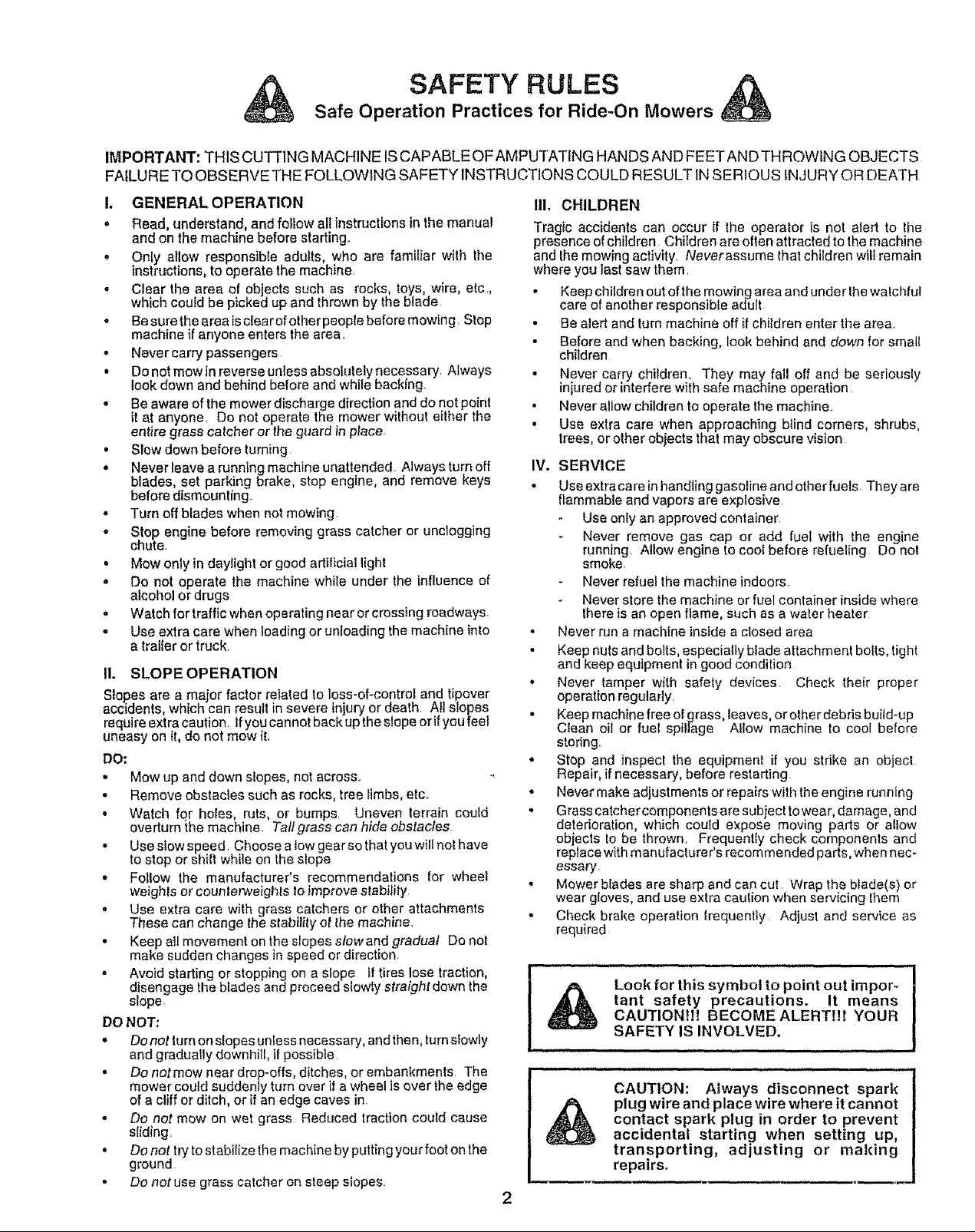
Safe Operation Practices for Ride-On Mowers
SAFETY RULES &
IMPORTANT: THIS CUTTING MACHINE ISCAPABLEOFAMPUTATING HANDS AND FEETAND THROWING OBJECTS
FAILURE TO OBSERVE THE FOLLOWING SAFETY INSTRUCTIONS COULD RESULT tNSERIOUS INJURY OR DEATH
I, GENERAL OPERATION
o Read, understand, and follow all instructions in the manual
and on the machine before starting+
• Only allow responsible adults, who are familiar with the
instructions, to operate the machine
• Clear the area of objects such as rocks, toys, wire, etc,
which could be picked up and thrown by the blade
• Besure the area is clear of otherpeople before mowing Stop
machine if anyone enters the area.
• Never carry passengers
• Do not mow in reverse unless absolutely necessary. Always
look down and behind before and while backing.
• Be aware of the mower discharge direction and do not point
it at anyone. Do not operate the mower without either the
entire grass catcheror the g_ard in ptace.
• Slow down before turning
° Never leave a runn{ng machine unattended. Always turn off
blades, set parking brake, stop engine, and remove keys
before dismounting.
,, Turn off blades when not mowing.
o Stop engine before removing grass catcher or unclogging
chute+
• Mow only in daylight or good artificial light
• Do not operate the machine while under the influence of
alcohol or drugs
° Watch for traffic when operating near or crossing roadways.
• Use extra care when loading or unloading the machine into
a trailer or truck
II. SLOPE OPERATION
Slopes are a major factor related to toss-of-control and tipover
accidents, which can result in severe injury or death. All slopes
require extra caution. If you cannot back up the slope orif you feel
uneasy on ft, do not mow it.
DO:
, Mow up and down slopes, not across+
• Remove obstacles such as rocks, tree Iimbs, etc+
• Watch for holes, ruts, or bumps Uneven terrain coutd
overturn the machine. Talt grass can hide obstacles
o Use slow speed. Choose a low gearso that you wilt not have
to stop or shift while on the slope
• Fotlow the manufacturer's recommendations for wheel
weights or counterweights Io improve slabilily
= Use extra care with grass catchers or other attachments
These can change the stability of the machine.
• Keep all movement on the slopes slowand gradual Do not
make sudden changes in speed or direction.
• Avoid starting or stopping on a slope tf tires lose traction,
disengage the blades and proceed slowly straight down the
slope+
DO NOT,
• Donotturnonstopesunlessnecessary, andthen, tumslowly
and gradually downhiit, if possible.
• Do not mow near drop-effs, ditches, or embankments The
mower could suddenly turn over if a wheel is over the edge
of a cliff or ditch, or if an edge caves in
o Do not mow on wet grass Reduced traction coutd cause
sliding,
• Do not tryto stabilize the machine by putting your foot on the
ground
. Do not use grass catcher on steep slopes.
III. CHILDREN
Tragic accidents can occur if the operator is not alert to the
presence of children Children are often attracted to the machine
and the mowing activity+ Neverassume that children wilt remain
where you last saw them.
• Keep children out of the mowing area and under the walchful
care of another responsible adult
• Be alert and turn machine off if chitdren enter the area..
• Before and when backing, look behind and down for smalt
children
• Never carry children. They may fail off and be seriousty
injured or interfere with safe machine operation.
• Never allow children to operate the machine..
• Use extra care when approaching blind corners, shrubs,
trees, or other objects that may obscure vision
IV. SERVICE
. Use extra care in handling gaso{ine and other fuels Theyare
flammable and vapors are explosive
Use only an approved container
Never remove gas cap or add fuel with the engine
running Allow engine to cool before refueling Do not
smoke.
Never refuel the machine indoors.
Never store the machine or fuel container inside where
there is an open flame, such as a water heater
• Never run a machine inside a closed area
• Keep nutsand bolts, especiatly blade attachment bolts, tight
and keep equipment in good condition
• Never tamper with safety devices. Check their proper
operation regularly.
• Keep machine free of grass, leaves, or other debris buitd-up
Ctean oil or fuel spillage Aflow machine to cool before
storing.
• Stop and inspect the equipment if you strike an object
Repair, if necessary, before restarting
• Never make adjustments or repairs with the engine running
° Grass catchercomponents are subject towear, damage, and
deterioration, which could expose moving parts or allow
objects to be thrown. Frequently check components and
replace with manufacturer's recommended parts, when nec-
essary.
• Mower b_ades are sharp and can cut, Wrap the blade(s) or
wear groves, and use extra caution when servicing them
• Check brake operation trequenfiy Adjust and service as
requ{red
i i , i,,,,,,,, ,, nlu,,,, ,u,i, i, i
rant safety precautions. It means
CAUTIONt!! BECOME ALERT!!! YOUR
Look for this symbol to point out impor- i
SAFETY IS INVOLVED.
CAUTION: Always disconnect spark
plug wire and place wire where it cannot
contact spark plug in order to prevent
accidental starting when setting up,
transporting, adjusting or making
repairs.
Page 3

CONGRATULATIONS on your purchase of a Sears
Tractor. It has been designed, engineered and manufac-
tured to give you the best possible dependability and
performance.
Should you experience any problem you cannot easily
remedy, please contact your nearest Sears Authorized
Service Center/Department. We have competent, well-
trained technicians and the proper tools to service or repair
this unit.
Please read and retain this manual. The instructions will
enable you to assemble and maintain your unit properly.
Always observe the "SAFETY RULES".
MODEL
NUMBER 917.257630
SERIAL
NUMBER
DATEOFPURCHASE
THE MODELAND SERIALNUMBERSWlLLBE FOUND
ON A PLATE UNDER THE SEAT.
YOU SHOULD RECORD BOTH SER{AL NUMBER AND
DATE OF PURCHASE AND KEEP IN A SAFE PLACE
FOR FUTURE REFERENCE.
PRODUCT SPECiFICATiONS
HORSEPOWER: 13.0
GASOLINE CAPACITY 5 QUARTS
AND TYPE: UNLEADED REGULAR
OIL TYPE (APl-SG): SAE 30 (above 32°F)
SAE 5W-30 (below 32°F)
OILCAPACITY: 3 PINTS
SPARK PLUG: CHAMPION RJI9LM
(GAP: .025") STD361458
VALVE CLEARANCE: INTAKE: .005" - .007"
EXHAUST: .009" - .011"
GROUND SPEED (MPH): FORWARD:
1st" 1.02
2rid 1.35
3rd 2.10
4th 3.14
5th 4.00
6th 5.12
REVERSE: 1.58
TIRE PRESSURE: FRONT: 14 PSi
REAR: 12 PSI
cHARGING SYSTEM: 3 AMPS BATTERY
5 AMPS HEADLIGHTS
BLADE BOLT TORQUE: 30-35 FT. LBS.
MAINTENANCE AGREEMENT
A Sears Maintenance Agreement is available on this prod-
uct. Contact your nearest Sears store for details.
CUSTOMER RESPONSIBILITIES
= Read and observe the safety rules.
- Follow a regularschedule in maintaining, caring for and
using your unit.
• Follow the instructions under"Customer Responsibili-
ties" and "Storage" sections of this owner's manual.
WARNING: This unit is equipped with an internal combus-
tion engine and should not be used on or near any unim-
proved forest-covered, brush-covered or grass-covered
land unless the engine's exhaust system is equipped with
a spark attester meeting applicable locat or state laws (if
any). Ifa spark arrester is used, it should be maintained in
effective working order by the operator.
In the state of California the above is required by law
(Section 4442 of the California Public Resources Code).
Other states may have similar laws. Federal laws apply on
federal lands. A spark arrester for the muffler is available
through your nearest Sears Authorized Service Center/
Department (See REPAIR PARTS sectio n of this manual).
i ii iii i i II
LIMITED TWO YEAR WARRANTY ON ELECTRIC START RIDING EQUIPMENT
For two (2) years from the date of purchase, if this riding equipmentis maintained, lubricatedand tuned up according to the
instructions in the owner's manual, Sears will repair or replace, free of charge, any parts found to be defective in material or
workmanship.
This Warrantydoes notcover:
o Expendable items which become worn duringnormal use, such as blades, spark plugs, air cleaners and belts.
o Tire replacement or repair caused by punctures from outside objects, such as nails, thoms, stumps, or glass.
• Repairs necessary because of operatorabuse, negligence, improper storage or accident orthe failure to maintain the
equipment according to the instructions contained in the owner's manual.
• Riding equipment used for commercialor rental purposes.
LIMITED 90 DAY WARRANTY ON BATTERY
For ninety (90) days from date of purchase,ff any battery includedwith this dding equipment proves defective in material or
workmanshipand our testingdeterminesthe battery willnothold a charge,Sears willreplace the batteryat nocharge.
WARRANTY SERVICE IS AVAILABLE BY RETURNING THE RIDING EQUIPMENT TO THE NEAREST SEARS SERVICE
CENTER/DEPARTMENT iN THE UNITED STATES.
This Warranty gives you specific legal rights, and you may also have other rights which may vary from state to state.
SEARS, ROEBUCK AND CO., D/817 WA, HOFFMAN ESTATES, ILLtNOIS 60179
I II ,, IH,, ii H i1,1, i , i i
3
Page 4
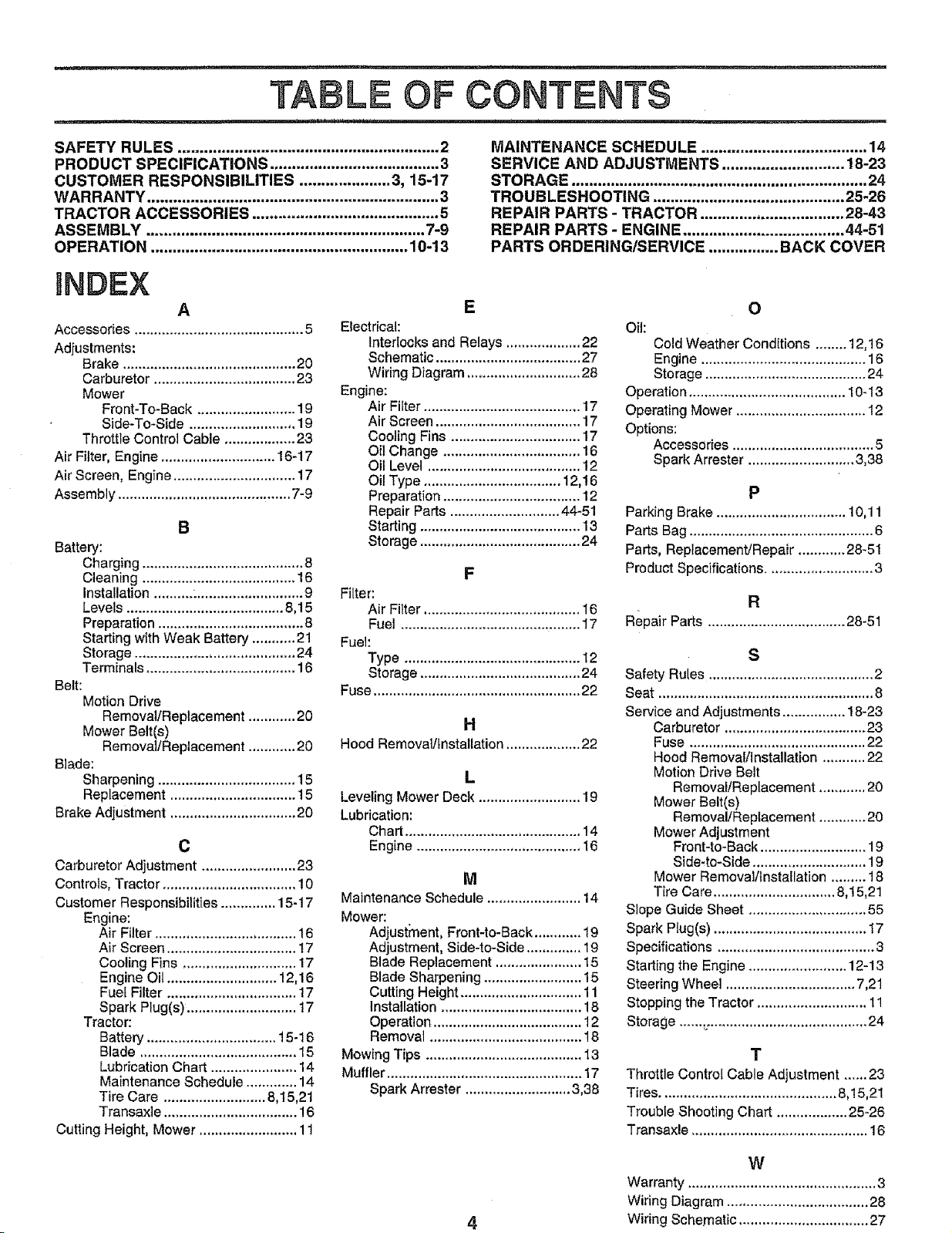
TABLE OF CONTENTS
SAFETY RULES ............................................................ 2
PRODUCT SPECIFICATIONS ....................................... 3
CUSTOMER RESPONSIBILITIES ..................... 3, 15-17
WARRANTY ................................................................... 3
TRACTOR ACCESSORIES ........................................... 5
ASSEMBLY ................................................................ 7-9
OPERATION ........................................................... 10-13
iNDEX
A
Accessories ........................................... 5
Adjustments:
Brake ............................................ 20
Carburetor .................................... 23
Mower
Front-To-Back ......................... 19
Side-To-Side ........................... 19
Throttle Control Cable .................. 23
Air Filter, Engine ............................. 16-17
Air Screen, Engine ............................... 17
Assembly ............................................ 7-9
B
Battery:
Charging ......................................... 8
Cleaning ....................................... 16
Installation .......... :........................... 9
Levels ........................................ 8,15
Preparation ..................................... 8
Starting with Weak Battery ........... 21
Storage ......................................... 24
Terminals ...................................... 16
Belt:
Motion Drive
Removal/Replacement ............ 20
Mower Belt(e)
Removal/Replacement ............ 20
Blade:
Sharpening ................................... 15
Replacement ................................ 15
Brake Adjustment ................................ 20
C
Carburetor Adjustment ........................ 23
Controls, Tractor .................................. 10
Customer Responsibilities .............. 15-t 7
Engine:
Air Filter .................................... 16
Air Screen ................................. 17
Cooling Fins ............................. 17
Engine Oil ............................ 12,16
Fuel Filter ................................. 17
Spark Plug(s). ........................... 17
Tractor:
Battery ................................. 15-16
Blade ........................................ 15
Lubrication Chart ...................... 14
Maintenance Schedule ............. 14
Tire Care .......................... 8,15,21
Transaxle .................................. 16
Cutting Height, Mower ......................... 11
Electrical:
Interlocks and Relays ................... 22
Schematic ..................................... 27
Wiring Diagram ............................. 28
Engine:
Air Filter ........................................ 17
Air Screen ..................................... 17
Cooling Fins ................................. 17
Oil Change ................................... 16
Oil Level ....................................... 12
Oil Type ................................... 12,16
Preparation ................................... 12
Repair Parts ............................ 44-51
Starting ......................................... 13
Storage ......................................... 24
Filter:
Air Filter ........................................ I6
Fuel .............................................. I7
Fuel:
Type ............................................. t 2
Storage ......................................... 24
Fuse ..................................................... 22
Hood Removal/installation ................... 22
Leveling Mower Deck .......................... 19
Lubrication:
Chart ............................................. 14
Engine .......................................... 16
Maintenance Schedule ........................ 14
Mower:
Adjustment, Front-to-Back ............ 19
Adjustment, Side-to-Side .............. 19
Blade Replacement ...................... 15
Blade Sharpening ......................... 15
Cutting Height ............................... 11
Installation .................................... 18
Operation ...................................... 12
Removal ....................................... 18
Mowing Tips ........................................ 13
Muffler .................................................. 17
Spark Arrestor ........................... 3,38
MAINTENANCE SCHEDULE ...................................... 14
SERVICE AND ADJUSTMENTS ............................ 18-23
STORAGE .................................................................... 24
TROUBLESHOOTING ............................................ 25-26
REPAIR PARTS - TRACTOR ................................. 28-43
REPAIR PARTS - ENGINE ..................................... 44-51
PARTS ORDERING/SERVICE ................ BACK COVER
E
Oil:
Cold Weather Conditions ........ 12,16
Engine .......................................... 16
Sto rage ......................................... 24
Operatic n ........................................ 1O-13
Operating Mower ................................. 12
Options:
Accessories .................................... 5
Spark Arrester ........................... 3,38
O
P
Parking Brake ................................. 10,11
Parts Bag ............................................... 6
Parts, Replacement/Repair ............ 28-51
F
Product Specifications ........................... 3
R
Repair Parts ................................... 28-51
S
Safety Rules .......................................... 2
Seat ....................................................... 8
H
L
M
Service and Adjustments ................ 18-23
Carburetor .................................... 23
Fuse ............................................. 22
Hood Removal/I nstallation ........... 22
Motion Drive Belt
Removal/Replacement ............ 20
Mower Belt(s)
Removal/Replacement ............ 20
Mower Adjustment
Front-to-Back ........................... 19
Side-to-Side ............................. 19
Mower Removal/Installation ......... 18
Tire Care ............................... 8,15,21
Slope Guide Sheet .............................. 55
Spark Plug(s) ....................................... 17
Specifications ........................................ 3
Starting the Engine ......................... 12-13
Steering Wheel ................................. 7,21
Stopping the Tractor ............................ l 1
Storage ...... _......................................... 24
T
Throttle Control Cable Adjustment ...... 23
Tires ............................................. 8,15,21
Trouble Shooting Chart .................. 25-26
Transaxle ............................................. 16
W
Warranty ................................................ 3
Wiring Diagram .................................... 28
4
Wiring Schematic ................................. 27
Page 5
u,,,,
, ,,,,l,u,, u ill
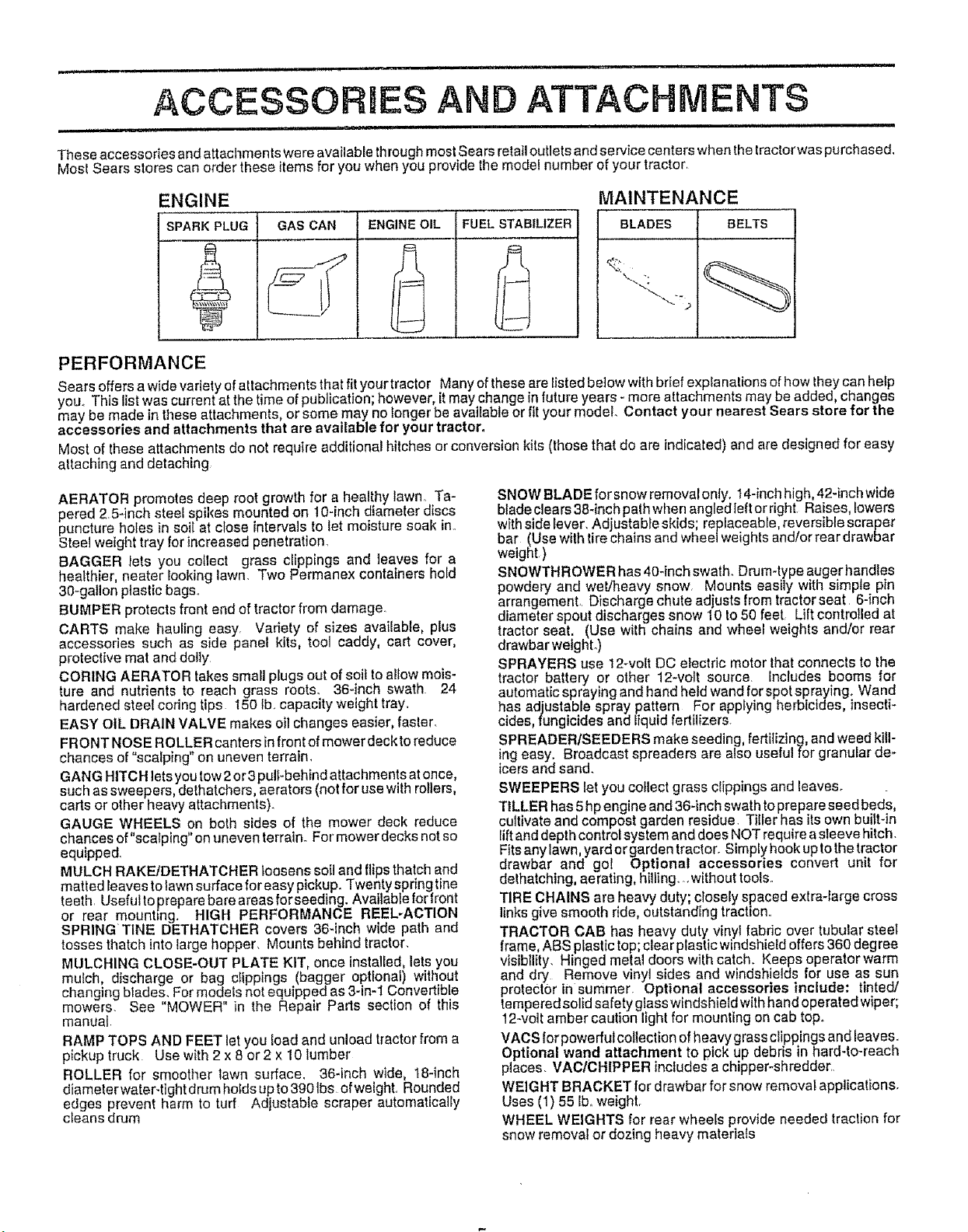
ACCESSORUES AND ATTAC ENTS
i. ,hi i, .i .. i ,i i uH,,, u,,,,,,,,,ul,,,,,,,,,
These accessories and attachments wereavailable throughmostSearsretail outlets and service centers whenthetractorwas purchased,
Most Sears stores can order these itemsfor you when you provide the model number of your tractor,
ENGINE
SPARK PLUG GAS CAN ENGINE OIL FUEL STABILIZER
MAINTENANCE
1
PERFORMANCE
Sears offersawide variety ofattachments that fit yourtractor Many oftheseare fisted below with brief expfanations of how they canhelp
you_This istwas currentat thetime ofpublication; however, it may change in future years - more attachments may be added, changes
may be made in these attachments or some may no longer be available or fit your model. Contact your nearest Sears store for the
accessories and attachments that are ava lable for your tractor,
Most of theseattachmenls do not require additional hitches or conversion kits (those that do are indicated) and are designedfor easy
attaching and detaching
AERATOR promotes deep root growth for a healthy lawn. Ta-
pered 2 5-inch steel spikes mounted on 10-inch diameter discs
puncture holes in soit at close intervals to let moisture soak in_
Steel weight tray for increased penetration.
BAGGER /ets you cotlect grass clippings and leaves for a
healthier, heater looking lawn. Two Permanex containers hold
30-gallon plastic bags_
BUMPER protects front end of tractor from damage.
CARTS make hauling easy Variety of sizes available, plus
accessories such as side panel kits, tool caddy, cart cover,
protective mat and dolly
CORING AERATOR takes small plugs out of soil to allow mois-
ture and nutrients to reach grass roots. 364nch swath 24
hardened steel coring tips I50 ib.. capacity weight tray.
EASY OIL DRAIN VALVE makes oil changes easier, faster
FRONT NOSE ROLLER canters in front of mower deck to reduce
chances of "scalping" on uneven terrain_
GANG HITCH lets you tow 2 or3 pull-behind attachments at once,
such as sweepers, dethatchers, aerators (not for use with rollers,
carts or other heavy attachments).
GAUGE WHEELS on both sides of the mower deck reduce
chances of"scalping" on uneven terrain. For mower decks not so
equipped,
MULCH RAKE/DETHATCHER loosens soil and flips thatch and
matted feaves to lawn surface for easy pickup. Twenty spring tine
teeth. Usefulto prepare bare areas for seeding. Available for front
or rear mount=ng. HIGH PERFORMANCE REEL-ACTION
SPRINGTINE DETHATCHER covers 36-inch wide path and
tosses thatch into large hopper, Mounts behind tractor.
MULCHING CLOSE-OUT PLATE KIT, once installed, lets you
mulch discharge or bag clippings (bagger optional) without
changing Mades, For models not equipped as 3- n-1 Convertible
mowers. See "MOWER" in the Repair Pads section of this
manual.
RAMP TOPS AND FEET let you load and unload tractor from a
pickup truck Use with 2 x 8 or2 x 10 lumber
ROLLER for smoother lawn surface. 36-inch wide, 18-inch
diameter water-tight drum hotds up to 390 Ibs of wetght, Rounded
edges prevent harm to turf Adjustable scraper automatically
cleans drum
SNOW BLADE for snowremovalonty. 14-inchhigh,42-inch wide
blade cJears38-inch palh when angled ]eftor right. Raises,lowers
with sidelever, Adjustable skids; replaceable, reversible scraper
bar (Use with tirechains and wheel weights and/orrear drawbar
weight.)
SNOWTHROWER has 40-inch swath. Drum4ype augerhandles
powdery and wet/heavy snow Mounts easily with simple pin
arrangement,, Discharge chute adjusts from tractor seat 6-inch
diameter spout discharges snow 10 to 50 feet Lift controlled at
tractor seat, (Use wilh chains and wheel weights and/or rear
drawbar weight.)
SPRAYERS use 12-volt DC electric motor thatconnects to the
tractor battery or other 12-volt source. Includes booms for
automatic spraying and hand held wand forspot spraying. Wand
has adjustable spray pattern For applying herbicides, insecti-
cides,fungicides and liquid fertilizers
SPREADER/SEEDERS make seeding, feditizing, andweed kill-
ing easy. Broadcast spreaders are also useful for granular de*
icers and sand.
SWEEPERS let you collect grass clippings and leaves.
TILLER has 5hpengine and36-inch swathtoprepareseed beds,
cultivate and compost garden residue. Tiller has its own built-in
Iiftanddepthcontrol system anddoes NOTrequireasleeve hitch.
Fitsany lawn,yard orgarden tractor. Simply hook uptothe tractor
drawbar and go! Optional accessories convert unit for
dethatching, aerating, hilling...without tools.
TIRE CHAlliS are heavy duty; closely spaced extra-large cross
links give smooth ride, outstanding traction..
TRACTOR CAB has heavy duty vinyl fabric over tubular steel
frame,ABS ptaslic top; clear plastic windshield offers 360degree
visibility. Hinged metal doors with catch. Keeps operator warm
and dry Remove vinyl sides and windshields for use as sun
protector in summer. Optional accessories include: tinted/
temperedsolid safety glasswindshield with handoperated wiper;
12-volt amber caution light for mounting on cab top.
VACS Iorpowerful collection of heavy grassclippings and leaves,
Optional wand attachment to pickup debris in hard-to-reach
places. VAC/CHIPPER includesa chipper-shredder
WEIGHTBRACKET for drawbarfor snow removal applications.
Uses (1) 55 Iboweight.
WHEEL WEIGHTS for rear wheets provide needed traction for
snow removal or dozing heavy materials
Page 6
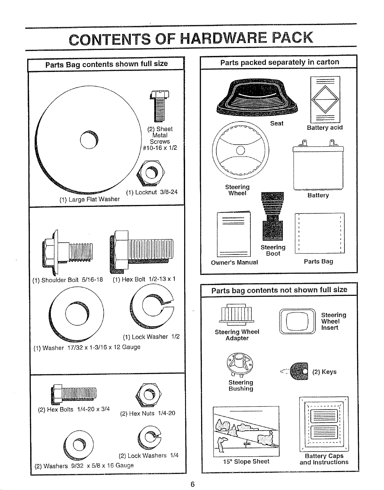
O
(2)Sheet
Screws
Metal
#10-16x1/2
(1)ShoutderBolt5/_6-18 (1)HexBolt 1/2-I3x 1
Seat
Steering
Wheel
Steering
Boot
Owner's Manual
Parts bag contents not shown full size
Battery acid
Battery
Parts Bag
i,==,, ,]ll
,li=,,J,,
t
t
(I) LockWasher 1/2
(t) Washer 17/32 x 1-3/16 x 12 Gauge
(2) Hex Bolts 1/4o20 x 3/4
{2) Hex Nuts 1/4-20
(2) Lock Washers 1/4
(2) Washers 9/32 x 5/8 x 16 Gauge
®
Steering Wheel Insert
Adapter
Steering
Bushing
t5 ° Slope Sheet
_ Steering
/
....Battery Caps
and Instructions
Wheel
(2) Keys
Page 7
ill
....................... ,m,l.i
i
ASSEMBLY
L .................... i u,-,, _ n lll n,u
Your new tractor has been assembled at the factory with exception of those parts left unassembled for shipping purposes,
To ensure safe and proper operation of your tractor all parts and hardware you assemble must be tightened securely. Use
the correct tools as necessary to insure proper tightness.
TOOLS REQUIRED FOR ASSEMBLY
A socket wrench set will make assembly easier, Standard
wrench sizes are listed°
(1) 5/16" wrench
(2) 7/16" wrenches
(1) 1/2" wrench
(1) 9/16" wrench
When right or left hand is mentioned in this manual, it
means when you are in tile operating position (seated
behind the steering wheel)
TO REMOVE TRACTOR FROM CARTON
UNPACK CARTON
• Remove all accessible loose parts and parts cartons
from carton (See page 6)
. Cut, from top to bottom, along lines on all four corners
of carton, and lay panels flat.
• Check for any additional loose parts or cartons and
remove.
(1) 314" wrench
Tire pressure gauge
Utility knife
BEFORE ROLLING TRACTOR OFF SKID
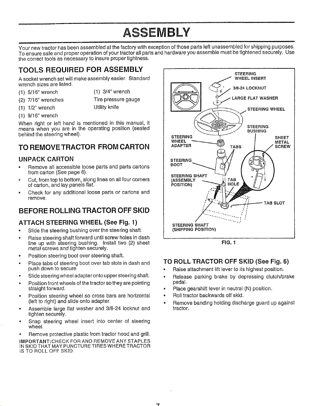
ATTACH STEERING WHEEL (See Fig. 1)
- Slide the steering bushing over the steering shaft°
• Raise steering shaft forward until screw holes in dash
line up with steering bushing, lnstall two (2) sheet
metal screws and tighten securely.
. Position steering boot over steering shaft,
. Place tabs of steering boot over tab slots in dash and
push down to secure
• Slide steering wheel adapter onto upper steering shaft,
° Position front wheels of the tractor so they are pointing
straight forward,
• Position steering wheel so cross bars are horizontal
(left to right) and slide onto adapter,
. Assemble large flat washer and 3/8-24 locknut and
tighten securely.
- Snap steering wheel insert into center of steering
wheel
. Remove protective plastic from tractor hood and grill
IMPORTANT:CHECK FOR AND REMOVE ANY STAPLES
1NSKID THAT MAY PUNCTURE TIRES WHERE TRACTOR
LSTO ROLL OFF SKID
t f
STEERING SHAFT
(SHIPPING POSITION)
FIG. 1
TO ROLL TRACTOR OFF SKID (See Fig. 6)
- Raise attachment lift lever to its highest position,
° Release parking brake by depressing clutch/brake
pedal.
. Place gearshift lever in neutral (N) position.
° Roll tractor backwards off skid.
- Remove banding holding discharge guard up against
tractor.
Page 8
ASSEMBLY
,ll,i _ , i,iJl1,111i,
HOW TO SET UP YOUR TRACTOR
PREPARE BATTERY (See Fig. 2)
CAUTION: Wear eye and face shield.
Wash hands or clothing immediately if
accidentally in contactwith battery acid.
Do not smoke. Fumes from charged
battery acid are explosive.
Read the instructions included with the
battery vent caps. Always wear gloves,
clothing and goggles to protect your
hands, skin and eyes.
Your tractor has a battery charging system which is
sufficientfornormal use However, periodicchargingofthe
battery with an automotive charger will extend its life,.
- See instructions packed with vent caps in parts bag.,
° Fill battery with acid, Fill each ceil until it reaches the
bottom of the vent wells. Do not overfill.
° AIIow battery to stand and settle for at least thirty
minutes,. After standing, check the battery cell acid
level° if below the vent wells, add more acid until the
correct level is reached
While battery is standing (after adding acid) and later, while
battery is being charged, continue with assembly of tractor.
IMPORTANT: TO MAXIMIZE THE LIFE OF YOUR
BATTERY, IT [S NECESSARY THAT THE BATTERY BE
CHARGED BEFORE USE FAILURE TO CHARGE
BATTERY CAN RESULT IN A SHORTENED BATTERY
LtFE.
• Charge battery at a rate of 6 amperes for 1 hour. Use
a 12 volt battery charger, Observe all safety precau-
tions required for battery charging.,
- Check the acid level after the battery is charged, If the
acid has fallen below the correct level, add distilled or
iron free water°
- Install the vent caps to cover the vent wells. Wash the
top of the battery with water to remove any acid, then
wipe dry.
• Check battery case for leakage to make sure that no
damage has occurred in handling,
• Dispose of excess battery acid, Neutralize acid for
disposal by adding it to two gallons of water in a five
gallon plastic container. Stir with a wooden or plastic
paddle while adding baking soda until the addition of
more soda causes no more foaming,
o
Follow instructions on how to install battery,
CUTAWAY VIEW _/, VENT CAP
L L__.,,J" , , ]j VENTWELL
i i i .....................
BATTERY
CELL ACID
LEVEL
FIG,, 2
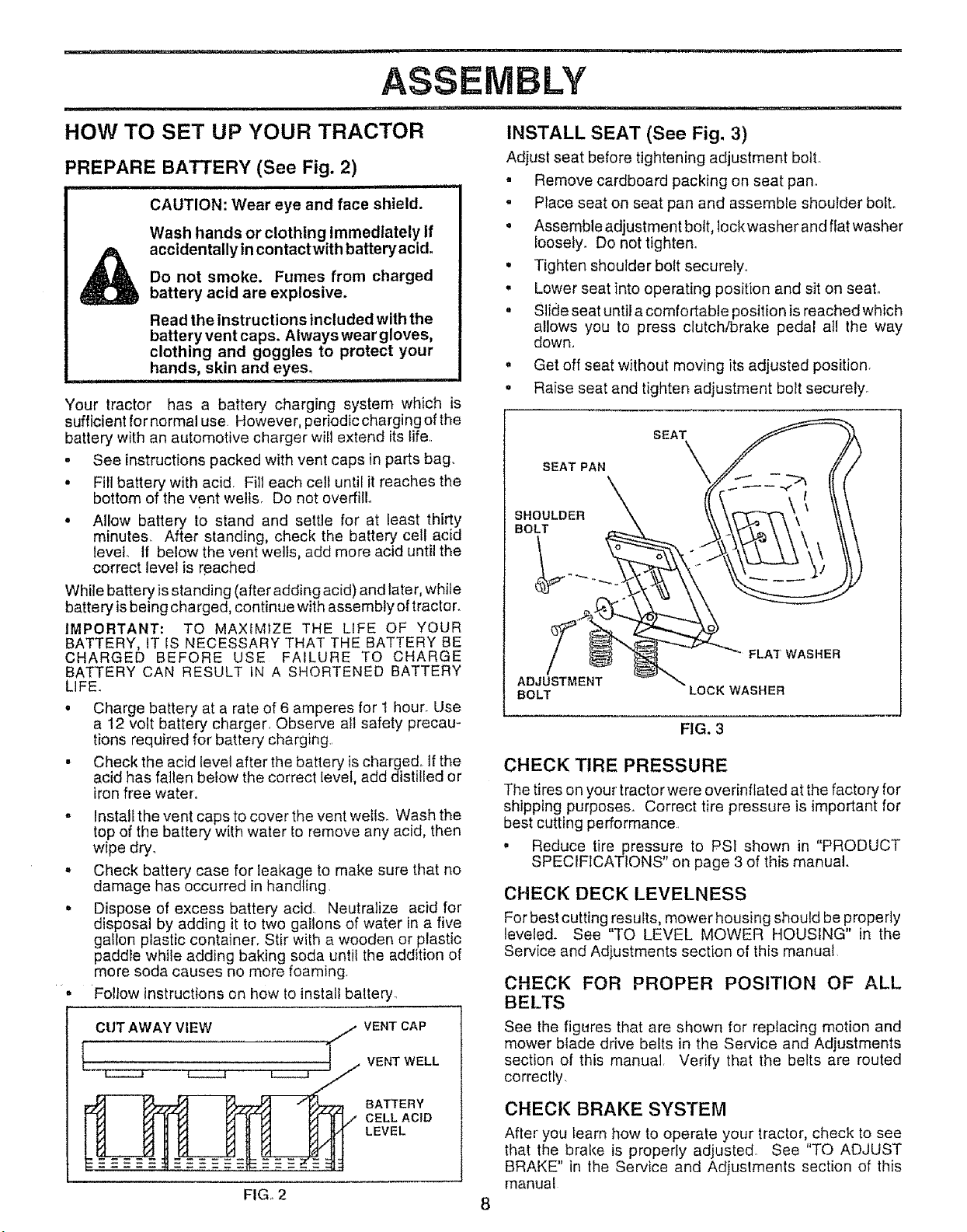
INSTALL SEAT (See Fig. 3)
Adjust seat before tightening adjustment boil
. Remove cardboard packing on seat pan°
. Place seat on seat pan and assemble shoulder bolt.
• Assemble adjustment bolt, lockwasher and flat washer
loosety. Do not tighten,,
. Tighten shoulderboft securely,,
• Lower seat into operating position and sit on seat°
• Slide seat until acomfortable position is reached which
allows you to press clutch/brake pedal atl the way
down.
. Get off seat without moving its adjusted position.
o Raise seat and tighten adjustment bolt securely_
SEAT
SEAT PAN
SHOULDER
BOLT
FLAT WASHER
ADJUSTMENT
BOLT
LOCK WASHER
FIG. 3
CHECK TIRE PRESSURE
The tires on your tractor were overinflated at the factory for
shipping purposes. Correct tire pressure ]s important for
best cutting performance
o Reduce tirepressure to PSI shown in "PRODUCT
SPECIFICATIONS" on page 3 of this manual.
CHECK DECK LEVELNESS
For best cutting results, mower housing should be property
leveled. See "TO LEVEL MOWER HOUSING" in the
Service and Adjustments section of this manual,
CHECK FOR PROPER POSITION OF ALl.
BELTS
See the figures that are shown for replacing motion and
mower blade drive belts in the Service and Adjustments
section of this manual. Verify that the belts are routed
correctly.
CHECKBRAKE SYSTEM
After you learn how to operate your tractor, check to see
that the brake is properly adjusted See "TO ADJUST
BRAKE" in the Service and Adjustments section of this
manual
8
Page 9
ASSEMBLY
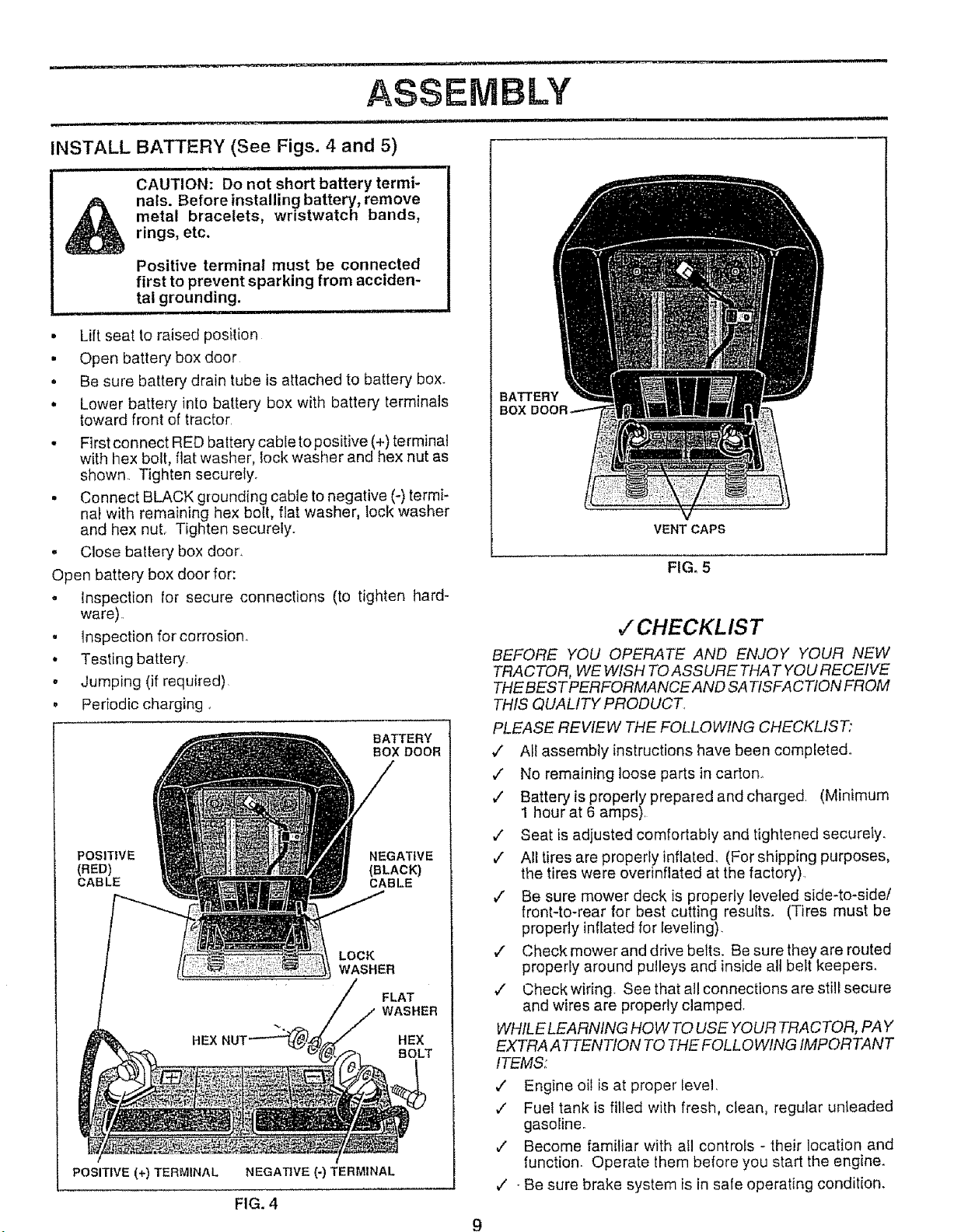
INSTALLiBATTERY (See Figs. 4 and 5)
, ill , ,ram, ill 11.,
CAUTION: Do not short battery termi-
nals. Before installing battery, remove
metal bracelets, wristwatch bands,
rings, etc.
Positive terminal must be connected
first to prevent sparking from acciden-
tal grounding.
. Lift seat to raised position
• Open battery box door
• Be sure battery drain tube is attached to battery box.
• Lower battery into battery box with battery terminals
toward front of tractor
• First connect RED battery cable to positive (+) terminal
with hex bolt, flat washer, lock washer and hex nut as
shown Tighten securely.
• Connect BLACK grounding cable to negative (-) termi-
nal with remaining hex bolt, flat washer, lock washer
and hex nuL Tighten securely.
, Close battery box door,
Open battery box door for:
• Inspection for secure connections (to tighten hard-
ware)
• Inspection for corrosion.
• Testing battery
o Jumping (if required)
• Periodic charging.
BATTERY
BOX DOOR
POSITIVE NEGATIVE
{RED) (BLACK)
CABLE CABLE
LOCK
WASHER
FLAT
WASHER
HEX HEX
POSITIVE (+) TERMINAL NEGATIVE (-) TERMINAL
FIG. 4
BOLT
BATTERY
BOX
VENT CAPS
FIG, 5
v"CHECKL IS T
BEFORE YOU OPERATE AND ENJOY YOUR NEW
TRACTOR, WE WISH TO ASSURE THAT YOU RECEIVE
THE BESTPERFORMANCE AND SA TtSFA CTtON FROM
THIS QUALITY PRODUCT.
PLEASE REVIEW THE FOLLOWING CHECKLIST,"
v" All assembly instructions have been completed.
,/ No remaining loose parts in carton_
,/ Battery is properly prepared and charged. (Minimum
1 hour at 6 amps).
,/ Seat is adjusted comfortably and tightened securely.
¢" All tires are properly inflated. (For shipping purposes,
the tires were overinflated at the factory).
¢" Be sure mower deck is properly leveted side-to-side/
front-to-rear for best cutting results. (Tires must be
properly inflated for leveling).
¢ Check mower and drive belts. Be sure they are routed
properly around pulleys and inside all belt keepers,
,/ Check wiring. See that all connections are still secure
and wires are properly clamped.
WHILE LEARNING HOW TO USE YOURTRACTOR, PAY
EXTRA A TTENTION TO THE FOLL O WING IMPORTANT
ITEMS:
,," Engine oil is at proper level.
v' Fuel tank is filled with fresh, clean, regular unleaded
gasoline°
v" Become familiar with all controls - their location and
function. Operate them before you start the engine.
¢" - Be sure brake system is in safe operating condition.
9
Page 10
= .................... ul =l Hm,
OPERATIO
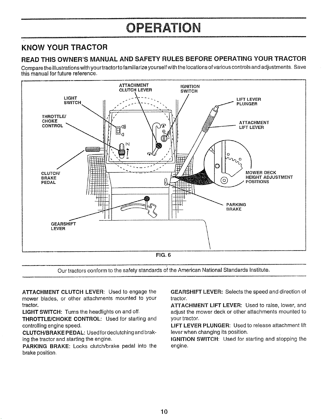
KNOW YOUR TRACTOR
READ THIS OWNER'S MANUAL AND SAFETY RULES BEFORE OPERATING YOUR TRACTOR
Compare the illustrationswith your tractor to familiarize you rself with the locations of various controls and adjustments, Save
this manual for future reference_
ATTACHMENT IGNITION
CLUTCH LEVER SWITCH
LIGHT LIFT LEVER
SWITCH PLUNGER
THROTTLE/
CHOKE
CONTROL
ATTACHMENT
LIFT LEVER
CLUTCH/
BRAKE
PEDAL
GEARSHIFT
LEVER
Our tractors conform to the safety standards oi the American National Standards Institute_
ATTACHMENT CLUTCH LEVER: Used to engage the
mower blades, or other attachments mounted to your
tractor.
LIGHT SWITCH: Turns the headlights on and off
THROTTLE/CHOKE CONTROL: Used for starting and
controlling engine speed.
CLUTCH/BRAKE PEDAL: Used fordeclutching and brak-
ing the tractor and starting the engine,
PARKING BRAKE: Locks clutch/brake pedal into the
brake position,
MOWER DECK
HEIGHT ADJUSTMENT
POSITIONS
PARKING
BRAKE
FIG_ 6
GEARSHIFT LEVER: Selects the speed and direction of
tractor.
ATTACHMENT LIFT LEVER: Used to raise, lower, and
adjust the mower deck or other attachments mounted to
your tractor°
LIFT LEVER PLUNGER: Used to release attachment lift
lever when changing itsposition°
IGNITION SWITCH: Used for starting and siopping the
engine.
10
Page 11
.................. i iil.l,i .i.i
[he operation of any tractor can result in foreign objects thrown into the eyes, which
can result in severe eye damage. Always wear safety glasses or eye shields while
operating your tractor or performing any adjustments or repairs, We recommendawide
vision safety mask for over the spectacles or standard safety glasses.
__ L,,IIIJ,J
OPERATION
i . .ill
HOW TO USE YOUR TRACTOR
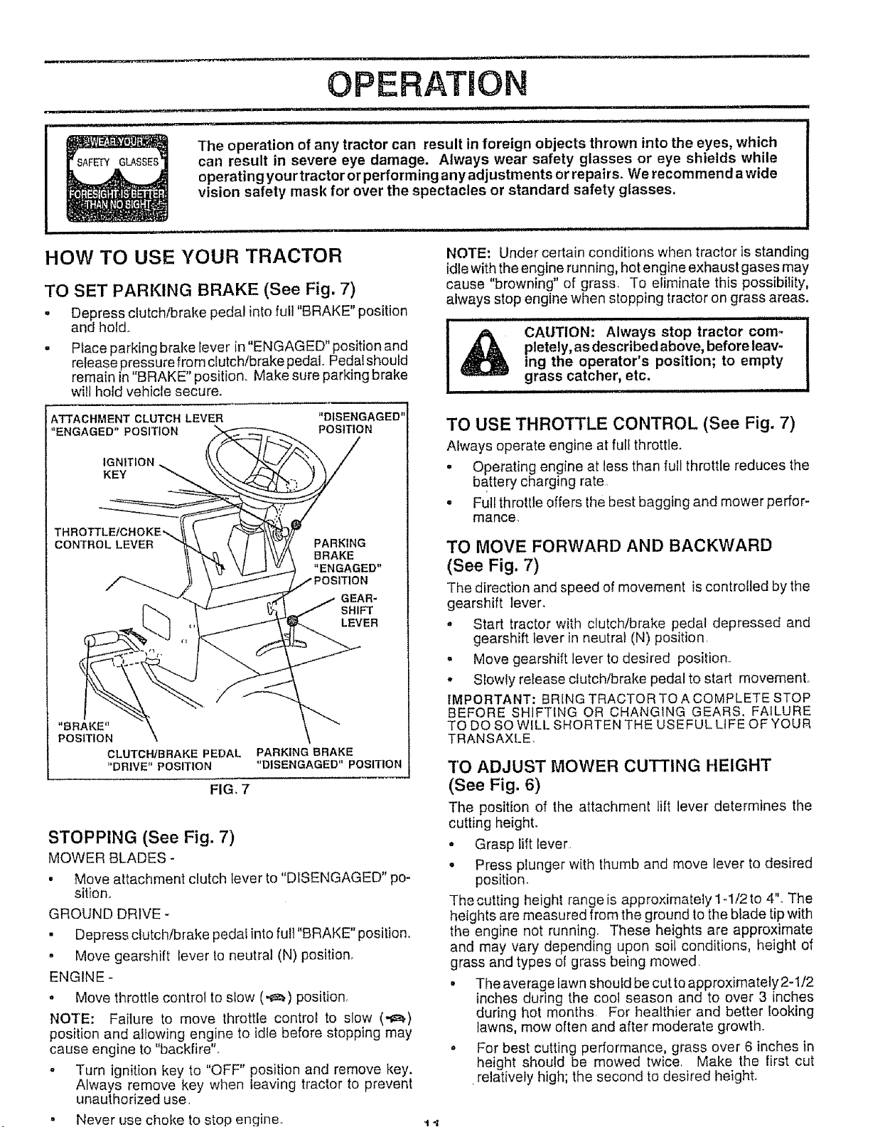
TO SET PARKING BRAKE (See Fig. 7)
. Depress clutch/brake pedal into full "BRAKE" position
and hold_
= Place parking brake lever in"ENGAGED" position and
release pressure from clutch/brake pedal. Pedalshould
remain in "BRAKE" position. Make sure parking brake
wilt hotd vehicle secure,.
ATTACHMENT CLUTCH LEVER
"ENGAGED" POSITION
IGNITION
KEY
THROTTLE/CHOKE%
CONTROL LEVER
"BRAKE"
POSITION
CLUTCHIBRAKE PEDAL
"DRIVE"POSITION
PARKING BRAKE
"DISENGAGED"POSITION
FIG, 7
STOPPING (See Fig. 7)
MOWER BLADES -
• Move attachment clutch lever to "DISENGAGED" po-
sition_
GROUND DRIVE -
• Depress clutch/brake pedat into full "BRAKE" position.
• Move gearshift lever to neutral (N) position.
ENGINE -
• Move throttle control to slow (-_) position,
NOTE: Failure to move throttle control to slow (,_)
position and allowing engine to idle before stopping may
cause engine to "backfire"..
- Turn ignition key to "OFF" position and remove key.
Always remove key when leaving tractor to prevent
unauthorized use,
Never use choke to stop engine_
"DISENGAGED"
POSITION
PARKING
BRAKE
"ENGAGED"
GEAR-
SHIFT
LEVER
NOTE: Under certain conditions when tractor is standing
idle with the engine running, hot engine exhaust gases may
cause "browning" of grass. To eliminate this possibility,
always stop engine when stopping tractor on grass areas,
l llll H lliNllll lllllllll lllll llllllii
pletely, as described above, before leav-
_ CAUTION: Always stop tractor com-
ing the operator's position; to empty
.....................grass catcher, etc.
TO USE THROTTLE CONTROL (See Fig. 7)
Always operate engine at full throttle.
• Operating engine at less than full throttle reduces the
battery charging rate.
• Full throttle offers the best bagging and mower perfor-
mance.
TO MOVE FORWARD AND BACKWARD
(See Fig, 7)
The direction and speed of movement iscontrolled by the
gearshift lever.
. Start tractor with clutch/brake pedal depressed and
gearshift lever in neutral (N) position.
o Move gearshift lever to desired position.
• Slowly release clutch/brake pedal to start movement.
IMPORTANT: BRING TRACTOR TO A COMPLETE STOP
BEFORE SHIFTING OR CHANGING GEARS. FAILURE
TO DO SO WILL SHORTEN THE USEFUL LIFE OF YOUR
TRANSAXLE
TO ADJUST MOWER CUTTING HEIGHT
(See Fig. 6)
The position of the attachment lift lever determines the
cutting height.
• Grasp lift lever
o Press plunger with thumb and move lever to desired
position
The cutting height range is approximately 1-t/2 to 4". The
heights are measured irom the ground to the blade tip with
the engine not running. These heights are approximate
and may vary depending upon soil conditions, height of
grass and types of grass being mowed.
• The average lawn should be cutto approximately2-1/2
inches during the cool season and to over 3 inches
during hot months, For healthier and better looking
lawns, mow often and after moderate growth.
• For best cutting performance, grass over 6 inches in
height should be mowed twice. Make the first cut
.relatively high; the second to desired height.
t4
Page 12
OPERATION
i i, i i, i, j
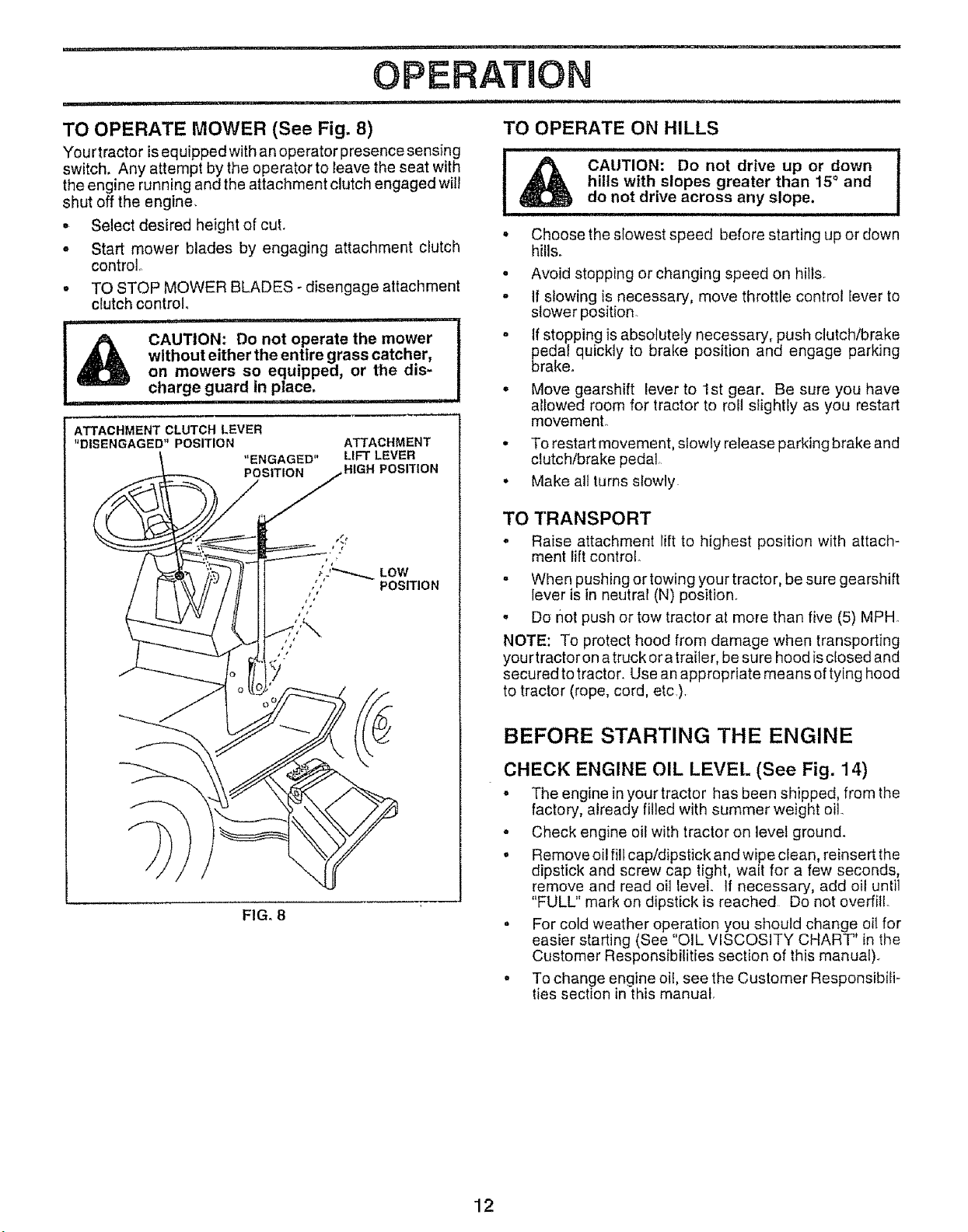
TO OPERATE MOWER (See Fig. 8) TO OPERATE ON HILLS
You rtractor isequipped with an operator presence sensing
switch, Any attempt by the operator to leave the seat with
the engine running and the attachment clutch engaged will
shut off the engine,
• Select desired height of cut. °
° Start mower blades by engaging attachment clutch
control°
° TO STOP MOWER BLADES - disengage attachment .
clutch control.
CAUTION: Do not operate the mower
without either the entire grass catcher,
l& ............................
ATTACHMENT CLUTCH LEVER
"DISENGAGED" POSITION
on mowers so equipped, or the dis-
charge guard in place.
.................. , ,HI ii
ATTACHMENT
"ENGAGED"
POSITION
LIFT LEVER
HIGH POSITION
Choose the slowest speed before starting up or down
hills.
Avoid stopping or changing speed on hills.
If slowing is necessary, move throttle control lever to
slower position.
If stopping is absolutely necessary, push clutch/brake
_edal quickly to brake position and engage parking
• Move gearshift lever to 1st gear. Be sure you have
allowed room for tractor to rotl slightly as you restart
movemenL
• To restart movement, sfowly release parking brake and
clutch/brake pedal.
• Make all turns slowly
TO TRANSPORT
= Raise attachment lift to highest position with attach-
ment lift control.
• When pushing or towing your tractor, be sure gearshift
lever is in neutral (N) position.
. Do not push or tow tractor at more than five (5) MPH
NOTE: To protect hood from damage when transporting
yourtractor ona truck ora trailer, be sure hood isclosed and
secured to tractor. Use an appropriate means of tying hood
to tractor (rope, cord, etc .).
CAUTION: Do not drive up or down
hills with slopes greater than 15° and
do not drive across any slope.
rake°
tl,,
FIG. 8
BEFORE STARTING THE ENGINE
CHECK ENGINE OIL LEVEL (See Fig. 14)
o The engine in your tractor has been shipped, from the
factory, already filled with summer weight oil.
- Check engine oil with tractor on level ground.
. Remove oil fibcap/dipstick and wipe clean, reinsert the
dipstick and screw cap tight, wait for a few seconds,
remove and read oil level. If necessary, add oil until
"FULL" mark on dipstick is reached Do not overfil!.
, For cold weather operation you should change oil for
easier starting (See "OIL VISCOSITY CHART" in the
Customer Responsibilities section of this manual).
, To change engine oil, see the Customer Responsibili-
ties section in this manual.
12
Page 13
i nl i I.Ill,II
OPERATIO
ADD GASOLINE
o Fill fuef tank Use fresh, clean, regular unleaded
gasoline (Use of leaded gasoline will increase carbon
and lead oxide deposits and reduce valve life),
IMPORTANT: WHEN OPERATING IN TEMPERATURES
BELOW 32°F(0°C), USE FRESH, CLEAN WINTER GRADE
GASOLINE TO HELP INSURE GOOD COLD WEATHER
STARTING.
WARNING: Experience indicates that alcohol blended
fuels (called gasohol or using ethanol or methanol) can
attract moisture which leads to separation and formation of
acids during storage Acidic gas can damage the fuel
system of an engine while in storage To avoid engine
problems, the fuel system should be emptied before stor*
age of 30 days or longer. Drain the gas tank, start the
engine and let it run until the fue! lines and carburetor are
empty. Use fresh fuel next season. See Storage Instruc-
tions for additional information. Never use engine or
carburetor cleaner products in the fuel tank or permanent
damage may occur°
filler neck. Do not overfill. Wipe off any
spilled oil or fuel. Do not store, spill or
use gasoline near an open flame.
TO START ENGINE (See Fig. 7)
When starting engine for the first time or if engine has run
out of fuel, itwill take extra cranking time to move fuel from
the tank to the engine.
. Depress clutch/brake pedal and set parking brake°
• Place gearshift lever in neutral (N) position
• Move attachment clutch to "DISENGAGED" position°
. Move throttle control lever to choke (\) position for
cold eng ne start. Forwarm eng ne start, move throttle
control to fast (.t_) position.
• Insert key into ignition andturn key clockwise to"START"
position and release key as soon as engine starts. Do
not run starter continuously for more than fifteen
seconds per minute If engine does not start after
several attempts, move throttle control to fast (,f_,)
position, wait a few minutes and try again_
• When engine starts, move throttle control to desired
position
• Allow engine to warm up for a few minutes before
engaging drive or attachments
NOTE: If at a high altitude (above 3000 feet) or in cold
temperatures (below 32°F), the carburetor fuel mixture
may need to be adjusted for best engine performance. See
"TO ADJUST CARBURETOR" in the Service and Adjust-
ments section of this manual
MOWING TIPS
. Tire chains cannot be used when the mower housing
is attached to tractor.
. Mower should be properly leveled for best mowing
performance See"TO LEVEL MOWER HOUSING" in
the Service and Adjustments section of this manual,
° The left hand side of mower should be used for trim-
ming_
- Drive so that clippings are discharged onto the area
that has been cut. Have the cut area to the right of the
machine, This will result in a more even distribution of
clippings and more uniform cutting
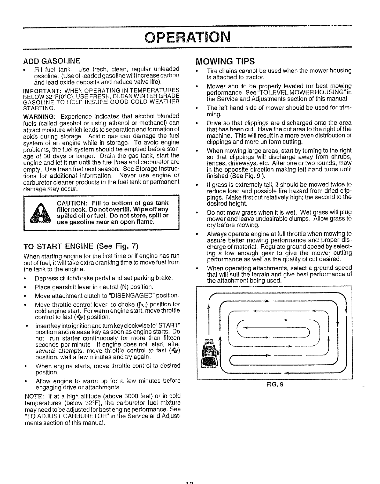
• When mowing large areas, start by turning to the right
so that clippings will discharge away from shrubs,
fences, driveways, etc. After one or two rounds, mow
in the opposite direction making left hand turns until
finished (See Fig 9 ).
. If grass is extremely tall, it should be mowed twice to
reduce load and possible fire hazard from dried clip-
pings. Make first cut relatively high; the second to the
desired heighL
• Do not mow grass when it is wet. Wet grass wilt plug
mower and leave undesirable clumps_ Allow grass to
dry before mowing.
• Always operate engine at full throttle when mowing to
assure better mowing performance and proper dis-
charge of material, Regulate ground speed by select-
ing a low enough gear to give the mower cutting
performance as well as the quality of cut desired.
o When operating attachments, select a ground speed
that wilt suit the terrain and give best performance of
the attachment being used°
FIG. 9
.i zl..j
Page 14
j UUl ii ,,i. i - , Ul ,lllU i
CUSTO RESPO ILmES
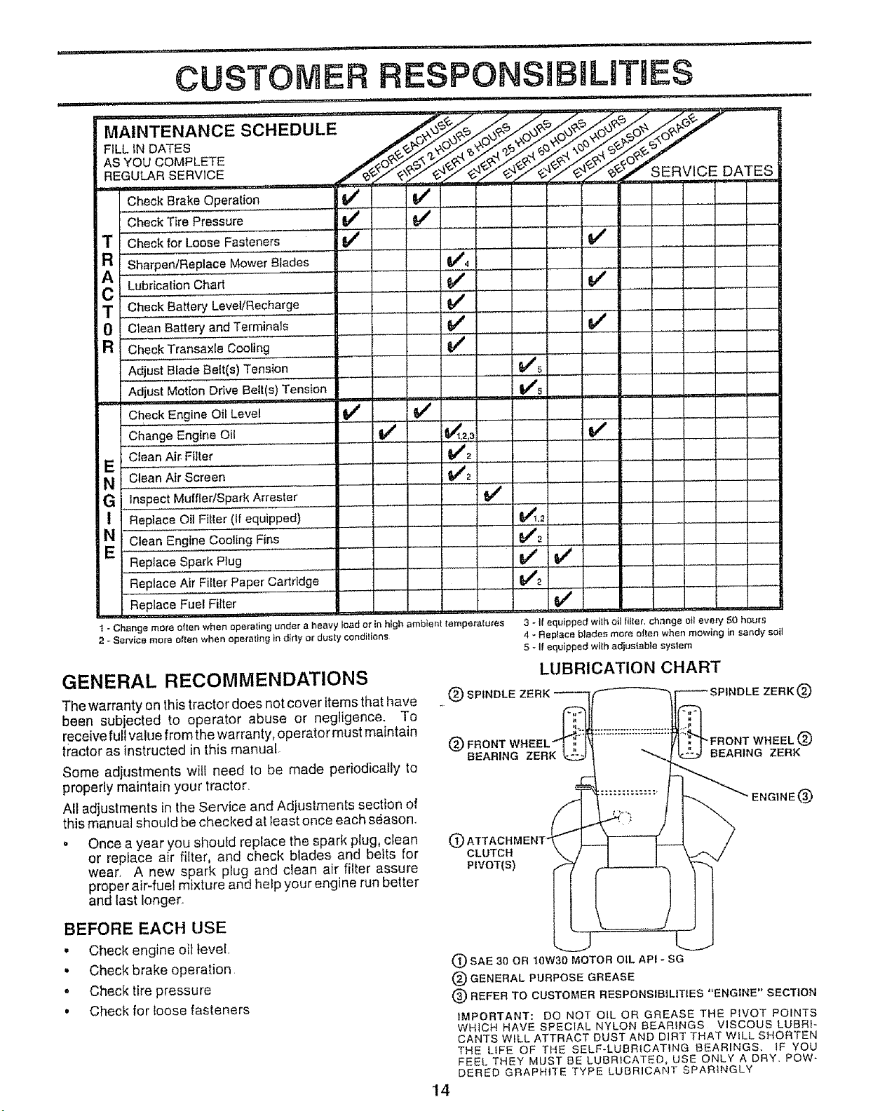
Check Brake Operation 6/ 6/
Check Tire Pressure if ,6/ .....
T Checkfor Loose Fasteners 6/ ...................................... 6/ :
Sharpen/Replace Mower Blades If4
AR ....................
C Lubrication Chart [t_
T Ch,eck,,,B,atte_,Level/Recharge,,, _ ........... V'
0 Clean Battery and Terminals 6/ V #
a Check Transaxte Cooling 6/ {
Adjust Blade Belt(s) Tension _,4_
Adjust Motion Drive Belt(s)Tension VP5
ChockEngineO,L ve;.......... iV' .....
Change Engine Oil if _t_.= tf
Clean Air:F!!!er .............. _2
N Clean Air Screen _./2
G Inspect Muffler/Spark Arrester
! Replace OIl Filter (If equipped)
v'
L. i
N Clean Engine Cooling Fins
Replace Spark Plug
Replace Air Filter Paper Cartridge
Replace Fue! Fitter
,,,,, , , ,, , ,
1 - Change more often when operating under a heavy load or in high amblent lemperatu_es
2 - Service more ellen when operating in dirty or duely conditions
GENERAL RECOMMENDATIONS
The warranty on this tractor does not cover items that have
been subjected to operator abuse or negligence. To
receive fuil value from the warranty, operator must maintain
tractor as instructed in this manual.
Some adjustments will need to be made periodically to
propedy maintain your tractor.
All adjustments in the Service and Adjustments section of
this manual should bechecked at least once each season.
o Once a year you should replace the spark plug, crean
or replace air filter, and check blades and belts for
wear. A new spark plug and clean air filter assure
proper air-fuel mixture and help your engine run better
and last longer.
BEFORE EACH USE
, Check engine oil level,
• Check brake operation
• Check!ire pressure
• Check for loose fasteners
3 _ It equipped wilh ell filter, change oil every 50 hours
4 _ Replace blades more ellen when mowing in sandy soil
5 - ff equipped wilh adjus|able system
LUBRICATION CHART
. (_) SPINDLE ZERK'___ SPINDLE ZERK (_
(_) FRONT WHEEL'___ ....... _]'-":_ FRONT WHEEL (_)
BEARING ZERK _ I -_._j _ BEARING ZERK
ENGINE '_
(P
CLUTCH
PIVOT(S)
(_) SAE 30 OR 10W30 MOTOR OIL API * SG
(_ GENERAL PURPOSE
(_ REFER TO CUSTOMER RESPONSIBILITIES "ENGINE" SECTION
IMPORTANT: DO NOT OIL OR GREASE THE PIVOT POINTS
WHICH HAVE SPECIAL NYLON BEARINGS VISCOUS LUBRI-
CANTS WILL ATTRACT DUST AND DIRT THAT WILL SHORTEN
THE LIFE OF THE SELF-LUBRICATING BEARINGS. tF YOU
FEEL THEY MUST BE LUBRICATED, USE ONLY A DRY. Pew -
DERED GRAPFH] E TYPE LUBRICANT SPARINGLY
14
GREASE
Page 15
iii, ll I,rtL =11 I I"'MI' Ir I'Ul I1'1 , I
CUSTO
.................. _ ,i ill lUll iiiJ,,,,
RESPONSIBILITIES
iI iiii
TRACTOR
Always observe safety rules when performing any mainte-
nance
BRAKE OPERATION
If tractor requires more than six (6) feet stopping distance
at high speed in highest gear, then brake must be adjusted,
(See "TO ADJUST BRAKE" in the Service and Adjust-
ments section of this manual)
TIRES
o Maintain proper air pressure in all tires (See "PROD-
UCT SPECIFICATIONS" on page 3 of this manual).
. Keep tires free of gasoline, oil, or insect control chemi-
cals which can harm rubber,
o Avoid stumps, stones, deep ruts, sharp objects and
other hazards that may cause tire damage.
BLADE CARE
For best results mower blades must be kept sharp. Re_
place bent or damaged blades.
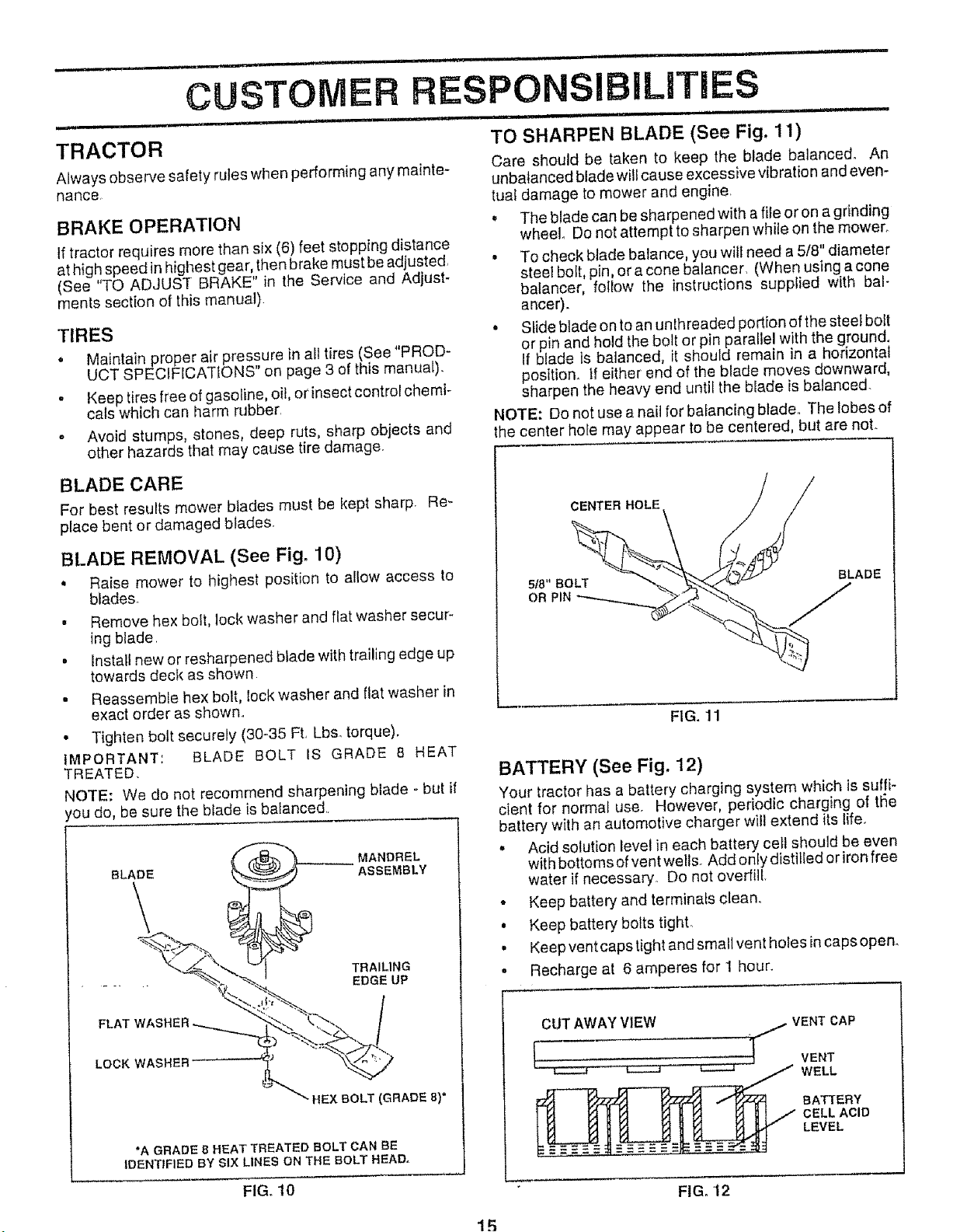
TO SHARPEN BLADE (See Fig. 11)
Care should be taken to keep the blade balanced° An
unbalanced blade will cause excessive vibration and even-
tua{ damage to mower and engine,
= The blade can be sharpened with a file or on a grinding
wheel Do not attempt to sharpen while on the mower.
• To check blade balance, you wilt need a 5/8" diameter
steel bolt, pin, or a cone balancer, (When using acone
balancer, follow the instructions supplied with bal-
ancer).
• Slide blade on to an unthreaded pod{on of the steel bolt
or pin and hold the bolt or pin parallel with the ground,
If blade is balanced, it should remain in a horizontal
position. If either' end of the blade moves downward,
sharpen the heavy end unt{I the blade is balanced.
NOTE: Do not use ana{( for bafanc{ng blade., The lobes of
the center hole may appear tobe centered, but are noL
CENTER HOLE
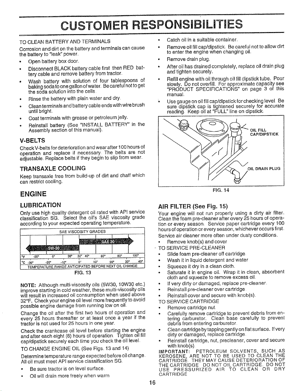
BLADE REMOVAL (See Fig. 10)
. Raise mower to highest position to allow access to
blades.
• Remove hex bolt, lock washer and flat washer secur_
ing b_ade.
° Install new or resharpened blade with trailing edge up
towards deck as shown
. Reassemble hex bolt, lock washer and flat washer in
exact order as shown.
• Tighten bolt securely (30-35 Ft. Lbs_torque).
IMPORTANT: BLADE BOLT IS GRADE 8 HEAT
TREATED.
NOTE: We do not recommend sharpening blade - but if
tou do, be sure the b_ade is balanced,
MANDREL
BLADE
ASSEMBLY
\
TRAILING
EDGE UP
S/8"BOLT BLADE
OR PIN J
FIG. 11
BATTERY (See Fig. 12)
Your tractor has a battery charging system which is suffi-
cient for normal use. However, periodic charging of tl_e
battery with an automotive charger wiJIextend its life.
,, Acid solution Jevel in each battery cell should be even
with bottoms of vent wells. Add only distilled orironfree
water if necessary. Do not overfill
° Keep battery and terminals clean.
• Keep battery bolts tight.
• Keep vent caps tight and small vent holes in caps open.
, Recharge at 6 amperes for 1 hour.
FLAT
LOCK WASHER
HEX BOLT (GRADE 8)*
*A GRADE B HEAT TREATED BOLT CAN BE
1DENT{FlED BY SiX LINES ON THE BOLT HEAD.
FIG. 10
15
CUT AWAY VIEW
{
.]_VENT CAP
VENT
WELL
BATTERY
CELL ACID
LEVEL
FIG. 12
Page 16
,,_,,,r,_ i , i,ii,l,rl,,rr ,, i i ii,,Ull,.,
CUSTOMER RESPONSIBILITIES
,,, i i,n,l,l,u,..,,i ul i , ,,nl,,., I ................ i n 1,1,11 . I
TO CLEAN BATTERY AND TERMINALS
Corrosion and dirt on the battery and terminals can cause
the battery to "leak" power_
° Open battery box door.
• Disconnect BLACK battery cable first then RED bat-
tery cable and remove battery from tractor,
. Wash battery with solution of four tablespoons of
baking soda toone gaUon of water, Becareful not to get
the soda solution into the cells.
• Rinse the battery with plain water and dry.
, Clean terminals and battery cable endswith wire brush
until brighL
o Coat terminals with grease or petroleum jelly.
- Reinstall battery (See "INSTALL BATTERY" in the
Assembly section of this manual).
V-BELTS
Check V-belts for deterioration and wear after 100 hours of
operation and replace if necessary. The belts are not
adjustable. Replace belts if they begin to slip from wear..
• Catch oil in a suitable container,
• Remove oil fill cap/dipstick. Be careful not to allow dirt
to enter the engine when changing oil
• Remove drain plug,
• After oil has drained completely, replace oil drain plug
and tighten securely.
• Refill engine with oil through oil fill dipstick tube. Pour
slowly. Do not overfill. For approximate capacity see
"PRODUCT SPECIFICATIONS" on page 3 of this
manual
_, Use gauge on oil fill cap/dipstick for checking level Be
sure dipstick cap is tightened securely for accurate
reading. Keep oil at "FULL" line on dipstick_
OIL FILL
CAPIDIPSTICK
TRANSAXLE COOLING
Keep transax{e free from build-up of dirt and chaff which
can restrict cooling.
ENGINE
LUBRICATION
Only use high quality detergent oil rated with API service
classification SGo Select the oil's SAE viscosity grade
according to your expected operating temperature°
SAE viscosiTY GRADES
i_F ';20" 0" 30" 32" 40 _ 60_ 80 _ 100"
i% -3o" ._" .'_o" o_ _o° , _o".............3oo ,, 40"
TEMPERATURE RANGE ANTICtPATED BEFORE NEXT OIL CHANGE ........
FIG. 13
NOTE: Although multi-viscosity oils (5W30, 10W30 etc.)
improve starting in cold weather, these multi-viscosity oils
will result in increased oif consumption when used above
32°F. Checkyour engine oil level more frequently to avoid
possible engine damage from running tow on oil.
Change the oil after the first two hours of operation and
every 25 hours thereafter or at least once a year if the
tractor is not used for 25 hours in one year.
Check the crankcase oil level before starting the engine
and after each eight (8) hours of operation Tighten oil fill
cap/dipstick securely each time you check the oil level.
TO CHANGE ENGINE OIL (See Figs.. 13 and 14)
Determine temperature range expected before oil change
A!l oll must meet API service classification SG
, Be sure tractor is on level surface,
• Oil will drain more freely when warm
OIL DRAIN PLUG
FtGo14
AIR FILTER (See Fig. 15)
Your engine will not run properly using a dirty air filter.
Clean the foam pre-cleaner after every 25 hours of opera-
lion or every season. Service paper cartridge every 100
hours of operation or every season, whichever occu rs first.
Service air cleaner more often under dusty conditions_
• Remove knob(s) and cover
- TO SERVICE PRE-CLEANER
• Slide foam pre-cleaner off cartridge
, Wash if in liquid detergent and water
• Squeeze it dry in a clean cloth.
, Saturate it in engine oil Wrap it in clean, absorbent
cloth and squeeze to remove excess oil.
,, If very dirty or damaged, replace pre-cleaner.
- Reinstall pre-cleaner over cartridge
• Reinstall cover and secure with knob(s).
TO SERVICE CARTRIDGE
• Remove cartridge nut.
• Carefully remove cartridge to prevent debris from en-
tering carburetor. Clean base carefully to prevent
debris from entering carburetor.
, Ctean cartridge by tapping gentfy on fiat surface, lfvery
dirty or damaged, replace cartridge
° Reinstall cartridge, nut, precleaner, cover and secure
with knob(s).
IMPORTANT: PETROLEUM SOLVENTS, SUCH AS
KEROSENE, ARE NOT TO BE USED TO CLEAN THE
CARTRIDGE THEY MAY CAUSE DETERIORATION OF
THE CARTRIDGE DO NOT OIL CARTRIDGE. DO NOT
USE PRESSURIZED AIR TO CLEAN OR DRY
CARTRIDGE
16
Page 17
i.,. ......_.. i,i...... II,JL i, i i , ii,lr.i ii
i i, ii i INN
CUSTO
iHi ,,,,J ill i i i
RESPO ILITIES
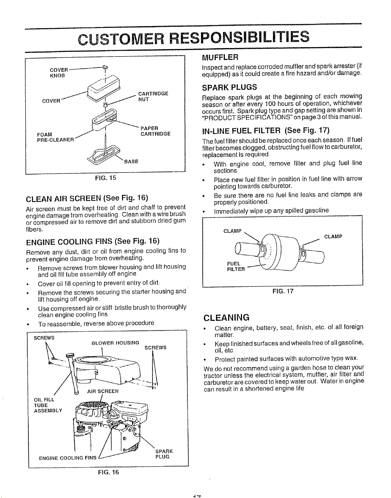
CLEAN AIR SCREEN (See Fig. 16)
Air screen must be kept free of dirt and chaff to prevent
engine damage from overheating Clean with a wire brush
or compressed air to remove dirt and stubborn dried gum
fibers.
ENGINE COOLING FINS (See Fig. 16)
Remove any dust, dirt or oil from engine cooling fins to
prevent engine damage from overheating..
. Remove screws from blower housing and lift housing
and oil flit tube assembly eli engine
. Cover oil fill opening to prevent entry of dirt.
. Remove the screws securing the starter housing and
lift housing off engine.
• Use compressed air or stiff bristle brush to thoroughly
clean engine cooling fins
• To reassemble, reverse above procedure.
SCREWS
OIL FILL
TUBE
ASSEMBLY
BLOWER I'tOUSlNG
SCREWS
AIR SCREEN
............. Jill '1 ............................... I1' III1'1 ',
MUFFLER
Inspect and replace corroded muffler and spark arrestor (if
equipped) as it could create a fire hazard and/or damage.
SPARK PLUGS
Replace spark plugs at the beginning of each mowing
season or after every 100 hours of operation, whichever
occurs first. Spark plug type and gap setting are shown in
"PRODUCT SPECIFICATIONS" on page 3 o{ this manual.
IN-LINE FUEL FILTER (See Fig. 17)
The fuel filter should be replaced once each season. Iffuel
filter becomes clogged, obstructing fue! flow to carburetor,
replacement is required
= With engine cool, remove filter and plug fuel line
sections
,, Place new tuet filter in position in fuel line with arrow
pointing towards carburetor.
. Be sure there are no fuel line leaks and clamps are
properly positioned°
• Immediately wipe up any spilled gasoline
CLAMP .
CLAMP
FILTER - __/"
FIGo 17
CLEANING
• Clean engine, battery, seat, finish, etc. of atl foreign
matter.
• Keep finished surfaces and wheels free of all gasoline,
oil, etc
,, Protect painied surfaces with automotive type wax.
We do not recommend using a garden hose to clean your
tractor unless the electrical system, muffler, air fitter and
carburetor are covered to keep waler out. Water inengine
can result in a shortened engine life
ENGINE COOLING FINS
SPARK
PLUG
FIGo 16
't-2
Page 18

L ....'.. 1.1..1111.111 i_/ i1..i.ii ......... i _.J_l .... i L . .11...11.. "1 .
SERVICE AN ADJUSTMENTS
........................... i ill, iHl,, . ,ill., i/ . i
........................................ i, iirl I i, qiill ,iiiH i tl,,, ,t'ltl,t'l_ '1 iiiU ,, iiiiiiiiii i I "q' J _
CAUTION: BEFORE PERFORMING ANY SERVICE OR ADJUSTMENTS:
- Depress clutch/brake pedal fully and set parklng brake,
° Place gearshift lever in neutral (N) position.
o Place attachment clutch in "DISENGAGED" position.
- Turn ignition key "OFF" and remove key°
, Make sure the blades and all moving parts have completely stopped.
= Disconnect spark plug wire from spark plug and place wire where itcannot come in contact with
plug,
,H,u H ll , =,,= i =
TO REMOVE MOWER (See Fig. 18)
Mower wilt be easier to remove from the right side of tractor
- Place attachment clutch in "DISENGAGED" position,
° Move attachment lift lever forward to lower mower to its
lowest position
. Roll beit off engine pulfey.
• Disconnect clutch rod from clutch lever by removing
retainer spring
, Disconnect anti-sway bar from chassis bracket by
removing retainer spring.
o Disconnect suspension arms from rear deck brackets
by removing retainer springs
• Disconnect front links from deck by removing retainer
springs,
o Raise lift iever toraise suspension arms, SIide mower
out from under tractor.
IMPORTANT: IF AN ATTACHMENT OTHER THAN THE
MOWER IS TO BE MOUNTED TO THE TRACTOR, THE
R.H. AND LH, SUSPENS}ON ARMS MUST BE REMOVED
FROM TRACTOR,
TO INSTALL MOWER (See Fig. 18)
° Raise attachment lift _ever to its highest position
, Slide mower under tractor with discharge guard to right
side of tractor
• Lower lift lever to its lowest position
o install mower in reverse order of removal instructions
CLUTCH
SUSPENSION
ARMS ENGINE
RETAINER : _'
SPRING
ANTI-SWAY BAR
/
RETAINER
SPRINGS
(BOTH SIDES)
FIG. 18
CLUTCH LEVER
SPRING
SPRINGS
(BOTH SIDES)
PULLEY
Page 19

SERVnCE AN
ADJUSTMENTS
TO LEVEL MOWER HOUSING
Adjust the mower while tractor is parked on level ground or
driveway. Make sure tires are properly inflated (See
"PRODUCT SPECIFICATIONS" on page 3). If tires are
over or under inflated, you wilt not properly adjust your
mower.
SIDE-TO-SIDE ADJUSTMENT (See Figs. 19 and 20)
You will need two (2) standard 2 x 4 short pieces of wood
to make the following adjustment. Similar blocks measur-
ing 1-1/2" thick may also be. used
• Raise mower with attachment lift control to allow two
(2) 1-1/2" thick blocks to be placed under rear edge of
mower,
• Place one block directly behind the left mandrel, Place
the remaining block under the stamped ridge on the
right rear edge of mower deck,
• Lower mower deck to its lowest height of cut position
(See "TO ADJUST MOWER CUTTING HEIGHT" in the
Operation section of this manual),
• On both sides of tractor, loosen, but do not remove, the
fasteners securing the adjustable pivot brackets to
frame. Both brackets must be loose enough to move
freely,
" Pull down firmly on suspension arm to remove any
slack in pivot bracket and hold while tightening rear
fastener first to secure Tighten remaining fastener.
• Repeat procedure on other side of tractor.
° Raise mower with attachment lift control and remove
blocks from under mower.
PLACE TWO 12) 1-_f2" THICK BLOCKS UNDER REAR EDGE OF
DECK (USE WOOD 2 X 4'S OR EQUIVo)
FRONT-TO-BACK ADJUSTMENT (See Figs, 21 and 22)
IMPORTANT: DECK MUST BE LEVEL SIDE-TO-SIDED IF
THE FOLLOWING FRONT-TO-BACK ADJUSTMENT IS
NECESSARY, BE SURE TO ADJUST BOTH FRONT LINKS
EQUALLY SO MOWER WILL STAY LEVEL SIDE-TO-
SIDE.
To obtain the best cutting results, the mower housing
should be adjusted so that the front is approximately 1/4" to
3/4" lower than the rear when the mower is in its highest
position.
Check adjustment on right side of tractor, Measure dis-
tance"D" directly in front and behind the mandrel at bottom
edge of mower housing as shown.
. Before making any necessary adjustments, check that
both front links are equal in length, Both links should
be approximately 10-3/8'L
. If links are not equal in length, adjust one link to same
length as other link.
• To lower front of mower loosen nut "E" on both front
links an equal number of turns,
- When distance "D" is 1/4" Io 3t4" lower at front than
rear, tighten nuts "F" against trunnion on both front
links
,, To raise front of mower, loosen nut"F" from trunnion on
both front links_ Tighten nut "E" on both front links an
equal number of turns
. When distance "D" is 1/4" to 3/4" lower at front than
rear, tighten nut"F" against trunnion on both front links,
Recheck side-to-side adjustment.
*\
. ,,', ' , , .f MANDREL
DIRECTLY
BEHIND
MOWER MUST BE IN LOWEST HEIGHT OF CUT POSITION
",- _ ,'_
UNDER
STAMPED _ ' ",/
RIDGE '_>
FIG. 19
SUSPENSION ARM
ADJUSTABLE PIVOT
BRACKET
PULL DOWN AND
TIGHTEN REAR
FASTENER FIRST
._ _;:o ,t ......... _ ._;_._
FIG. 21
BOTH FRONT LINKS MUST BE EQUAL IN LENGTH
NUT "E"
NU'[ "F"
FRONT LINKS TRUNNtON
Page 20

i 11J i i i ......................iii ,1_1 iii ,i,i ,
SERVICE AN ADJUSTMENTS
IIM i , i,ii , i,,,rl,,_,l r , ,i..... i1,,1_ ................ i, ,,i
TO REPLACE MOWER BLADE DRIVE BELT
(See Fig. 23)
The mower blade drive belt may be replaced without tools..
Park the tractor on level surface. Engage parking brake..
BELT REMOVAL -
• Place attachmen{ clutch in"DISENGAGED" position.
• Move attachment tilt tever forward to lower mower to its
lowest position.
,, Roll belt off engine pulley°
• Work belt off both mandrel pulleys and idler pulleys..
o Pull belt away from mower.
BELT INSTALLATION -
,, Install new bett in reverse order of removal°
,, Make sure belt is in all pulley grooves and inside all belt
guides.
ENGINE PULLEY
MANDREL IDLER
PULLEY PULLEYS
MANDREL
PULLEY
FIG. 23
WITH PARKING BRAKE "ENGAGED"
NUT "A"
JAM NUT
ERATtNG
M
FIG. 24
TO REPLACE MOTION DRIVE BELT
(See Fig. 25)
Park the tractor on level surface Engage parking brake
For assistance, there Jsa belt installation guide decal on
bottom side of left footrest,.
• Remove mower (See "TO REMOVE MOWER" in this
section of this manual.)
• Remove upper belt keeper.
• Remove belt from stationary idler and clutching idler
. Pull belt slack toward rear of tractor Remove belt
upwards from transax[e puIley by deflecting belt keep-
erSo
o Pull belt toward front of tractor and remove downwards
from around engine pulley.
- Install new belt by reversing above procedure.
IMPORTANT: MAKE SURE UPPER BELT KEEPER IS
POSITIONED PROPERLY BETWEEN LOCATOR TABS
TO ADJUST BRAKE (See Fig. 24)
Your tractor is equipped with an adjustable brake system
which is mounted on the right side of the transaxle.
l! tractor requires more than six (6) feet stopping distance
at high speed in highest gear, then brake must be adjusted.
,, Depress clutch/brake pedal and engage parking brake
o Measure distance between brake operating arm and
nut "A" on brake rod.
, tf distance is other than 1-1/2", disengage parking
brake, loosen jam nut and turn nut "A" until distance
becomes 1-1/2". Retighten jam nut against nut "A".
,, Engage parking brake and recheck distance
• Road testtractor for proper stopping distance as stated
above. Readjust if necessary. If stopping distance is
stil_ greater than six (6) feet in highest gear, further
maintenance is necessary. Contact your nearest au-
thorized service center/department
PULLEY
CLUTCHING
IDLER
STATIONARY
IDLER
PULLEY
20 FIG. 25
TABS
KEEPER
Page 21

SERVmCE AN ADJUSTMENTS
i, ,iH HH H,,, I ,U I
TO ADJUST STEERING WHEEl ALIGNMENT
If steering wheel crossbars are not horizontal (left to right)
when wheels are positioned straight forward, remove steer
ing wheel and reassemble per instructions inthe Assembly
section of this manual
FRONT WHEEL TOE-INICAMBER
The front wheeI toe in and camber are not adjustable on
your tractor If damage has occurred to affect the front
wheel toe-in or camber, contact your nearest authorized
service center/department
TO REMOVE WHEEL FOR REPAIRS
(See Fig 26)
,, Block up axle securely
* Remove axle cover, retaining ring and washers to altow
wheel removal (rear wheel contains a square key - Do
not lose)
• Repair tire and reassemble
, On rear wheels only: align grooves in rear wheel hub
and axle insert square key
• Repface washers and snap retaining ring securely in
axle groove
, Replace axle cover
WASHERS
RETAINING
RING
TO START ENGINE WITH A WEAl( BATTERY
(See Fig. 27)
ate explosive gases Keep sparks, flame
and smoking materials away from bat-
!_ AUTION: Lead-acid batteries gener-
HHHH
ff your battery is too weak to start the engine, it should be
recharged. If "jumper cables" are used for emergency
starting, follow this procedure:
IMPORTANT: YOU R TRACTOR IS EQUIPPED WITH A 12
VOLT NEGATIVE GROUNDED SYSTEM THE OTHER
VEHICLE MUST ALSO BE A 12 VOLT NEGATIVE
GROUNDED SYSTEM. DO NOT USE YOUR TRACTOR
BATTERY TO START OTHER VEHICLES,
TO ATTACH JUMPER CABLES
• Connect each end of the RED cable to the POSITIVE
(+) terminal of each batLery, taking care not to short
against chassis
,, Connect one end of the BLACK cable to the NEGA _
TIVE (-) terminal of lully charged baLtery
o Connect the other end of the BLACK cable to good
CHASSIS GROUND, away from [ueitank and battery
TO REMOVE CABLES, REVERSE ORDER
,, BLACK cable first from chassis and then trom the fully
charged battery
- RED cable last from both batteries
POSITIVE TERMINAL NEGATIVE TERMINAL
teries Always wear eye protection
when around batteries
AXLE COVER
J
_"SQUARE KEY
(REAR WHEEL ONLY)
FIG. 26
CHASSIS
CABLES
CHARGED
BATTERY
POSITIVE TERMINAL NEGATIVE TERMINAL
FIG,, 27
Page 22

=,,, M,, ,....... i,,=,, =
SERVICE AND ADJUSTMENTS
............................. i
TO REPLACE HEADLIGHT BULB
" Raise hood
• Pull bulb holder out of the hole in the backside of the
grill.
= Replace bulb in holder and push bulb holder securely
back into the ho_e in the backside of the grill.
. Close hood.
INTERLOCKS AND RELAYS
Loose or damaged wiring may cause your tractor to run
poorly, stop running, or prevent it from starting
• Check wiring. See electrical wiring diagram in the
Repair Parts section of this manual..
TO REPLACE FUSE
Replace with 30 amp automotive-type plug-in fuse. The
fuse holder is iecated behind the dash.
TO REMOVE HOOD AND GRILL ASSEMBLY
(See Fig. 28)
• Ratse hood,
• Unsnap headlight wire connector.
• Stand infront of tractor. G rasp hood at sides, tilt toward
engine and lift off of tractor.
• To replace, reverse above procedures.
HOOD
HEADLIGHT
WIRE
CONNECTOR
FIG. 28
22
Page 23

i ill ii,l,ll_ i iJ i i i
SERVmCE AN
i i lllll ii ii, ,i i,i i i ,i,Jl ii
ENGINE
TO ADJUST THROTTLE CONTROL CABLE
(See Fig. 29)
The throttle control has been preset at the factory and
adjustment should not be necessary. Check adjustment as
described below before loosening cable. If adjustment is
necessary, proceed as follows:
• With engine not running, move throttle control lever
from s_ow (._) to choke ( \ ) position. Slowly move
ever from choke ( \ ) to fast (.'_) position.
• Check that holes"A" ingovernor control lever and hole
in governor plate line-up. Jfholes "A"are not aligned,
loosen clamp screw and move throttle cable until holes
are aligned.. Tighten clamp screw securely.
GOVERNOR
CONTROL LEVER
GOVERNOR
CONTROL PLATE
FINAL SETTING -
• Start engine and allow to warm for five minutes. Make
fina_adjustments with engine running and shift/motion
control lever in neut[al (N) position.
• Move throttle control lever to slow (._) position. With
finger, rotate and hold throttie lever against idle speed
screw. Turn idle speed screw to attain 1750 RPM.
• While still holding throttle lever against idle s_,eed
screw, turn idle mixture valve in (clockwise) until en-
gine begins to die and then turn out (counterclockwise)
until engine runs rough. Turn valve to a point midway
between those two positions. Release throttle lever.
ACCELERATION TEST
o Move throttle control lever from slow (-_.) to fast (,@)
position. If engine hesitates or dies, turn idle mixture
valve out (counterclockwise) 1/8 turn. Repeat test and
continue to adjust, if necessary, until engine acceler-
ates smoothly.
High speed stop is factory adjusted. Do not adjust -
damage may result.
IMPORTANT: NEVER TAMPER WITH THE ENGINE
GOVERNOR, WHICH IS FACTORY SET FOR PROPER
ENGINE SPEED OVERSPEEDtNG THE ENGINE ABOVE
THE FACTORY HIGH SPEED SETTING CAN BE
DANGEROUS. IF YOU THINK THE ENGINE-GOVERNED
HIGH SPEED NEEDS ADJUSTING, CONTACT YOUR
NEAREST AUTHORIZED SERVICE CENTER/
DEPARTMENT, WHICH HAS PROPER EQUIPMENT AND
EXPERIENCE TO MAKE ANY NECESSARY
ADJUSTMENTS.
HOLES"A" CLAMP THROTTLE
SCREW CABLE
FIG., 29
TO ADJUST CARBURETOR (See Fig. 30)
The carburetor has been preset at the factory and adjust-
ment should not be necessary. However, minor adjust-
ment may be required to compensate for differences in fuel,
temperature, aft[tude or load if the carburetor does need
adjustment, proceed as follows:
In general, turning idle mixture valve in (clockwise) de-
creases the supply of fue! to the engine giving atearier fuel/
air mixture. Turning the idle mixture vatve out (counter-
clockwise) increases the supply of fuel to the engine giving
a richer fuet/aJr mixture..
IMPORTANT: DAMAGE TO THE NEEDLE VALVE AND
THE SEAT tN CARBURETOR MAY RESULT IF SCREW IS
TURNED IN TOO TIGHT.
PRELIMINARY SETTING -
,, Air cleaner assembly must be assembled to the carbu-
retor when making carburetor adjustments.
• Be sure the throttle control cable is adjusted properly
(see above)
• With engine off turn idle mixture valve in (clockwise)
closing it finger tight and then turn out (counterclock-
wise) 1 fullturn
THROTTLE IDLE SPEED
LEVER SCREW
IDLE MIXTURE
VALVE
FIG. 30
'9"4
Page 24

Immediately prepare your tractor for storage at the end of ENGIN E
the season or if the tractor will not be used for 30 days or
more.
, ,,, ,,,,,, ,,,,,,,,, ,,,,,,,u
CAUTION: Never store the tractor with I
gasoline in the tank inside a building I
where fumes may reach an open flame I
or spark. Allow the engine to coot I
before storing in any enclosure. J
= = , H ,,,,,H, ,,,,,,,,,,,
TRACTOR
Remove mower from tractor for winter storage. When
mower is to be stored for a period of time, clean it thor-
oughly, remove all dirt, grease, leaves, etco Store in a
clean, dry area.
. Clean entire tractor (See"CLEANING"in the Customer
Responsibilities section of this manual).
. Inspect and replace belts, if necessary (See belt re-
placement instructions in the Service and Adjustments
section of this manual),
• Lubricate as shown in the Customer Responsibilities
section of this manual,,
• Be sure that all nuts, bolts and screws are securely
fastened, Inspect moving parts for damage, breakage
FUEL SYSTEM
|
IMPORTANT: IT IS IMPORTANT TO PREVENT GUM
DEPOSITS FROM FORMING IN ESSENTIAL FUEL
SYSTEM PARTS SUCH AS CARBURETOR, FUEL FILTER,
FUEL HOSE, OR TANK DURING STORAGE. ALSO,
EXPERIENCE INDICATES THAT ALCOHOL BLENDED
FUELS (CALLED GASOHOL OR USING ETHANOL OR
METHANOL) CAN ATTRACT MOISTURE WHICH LEADS
TO SEPARATION AND FORMATION OF ACIDS DURING
STORAGE. ACEDIC GAS CAN DAMAGE THE FUEL
SYSTEM OF AN ENGINE WHILE IN STORAGE..
• Drain the fuel tank,
• Start the engine and let it run until the fuel lines and
carburetor are empty.,
- Never use engine or carburetor cleaner products in the
fuef tank or permanent damage may occur
• Use fresh fuel next season
NOTE: Fuet stabilizer is an acceptable alternative in
minimizing the formation of fuel gum deposits during stor-
age. Add stabilizer to gasoline in fuel tank or storage
container, Always follow the mix ratio found on stabilizer
container° Run engine at least 10 minutes after adding
stabilizer to allow the stabilizer to reach the carburetor. Do
not drain the gas tank and carburetor if using fuel stabilizer,
and wear, Replace if necessary°
° Touch up all rusted or chipped paint surfaces; sand
lightly before painting
BATTERY
• Fully charge the battery for storage,
. After a period of time in storage, battery may require
recharging-
. To help prevent corrosion and power leakage during
long periods of storage, battery cables should be
disconnected and battery cleaned thoroughly (see 'q'O
CLEAN BATTERY AND TERMINALS" in the Cus-
tomer Responsibilities section of this manuaI),
. After cleaning, leave cables disconnected and place
ENGINE OIL
Drain oil (with engine warm) and replace with clean engine
oil (See "ENGINE" in the Customer Responsibilities
section of this manual)
CYLINDERS
- Remove spark plug(s).
• Pour one ounce of oil through spark plug hole(s) into
cylinder(s),.
o Turn ignition key to"START" position for a few seconds
to distribute oil.
• Replace with new spark plug(s)
cables where they cannot come in contact with battery
terminals,
. Be sure battery drain tube is securely attached,
o If battery is removed from tractor for storage, do not
store battery directly on concrete or damp surfaces.
OTHER
o Do not store gasoline from one season to another.
• Replace your gasoline can if your can starts to rust
Rust and/or dirt in your gasoline will cause problems
° If possible, store your tractor indoors and cover it to
give protection from dust and dirt,
. Cover your tractor with a suitable protective cover that
does not retain moisture Do net use pJastic. Plastic
cannot breathe which al!ows condensation to form and
will cause your tractor to rust
IMPORTANT: NEVER COVER TRACTOR WHILE ENGINE
AND EXHAUST AREAS ARE STILL WARM
24
Page 25

TROUBLESHOOTING POmNTS
i ....................................
PROBLEM CAUSE CORRECTION
Wlll not start
Hard to start
ii iin i iqnll
Engine will not turn over
1 Out of fuel
2 Engine not "CHOKED" properly
3 Engine flooded
4, Bad spark plug
5 Dirty air rifler
6 Dirty fuel filter
7 Water in fuel,
8. Loose or damaged wiring.
9_ Carburetor out of adjustment
10 Engine vafves out of adjustment
t Dirty air fitter
2 Bad spark plug
3 Weaker dead battery.
4 Didy fuel filler
5, Stale or dirty fuel.
6, Loose or damaged wiring
7 Carburetor out of adjustment
8,
Engine valves out of adjustment
JJ
1 Clutch/brake pedal not depressed
2 Attachment clutch is engaged.
3 Weak or dead battery,
4 Brown fuse,
5 Corroded battery terminals
6_ Loose or damaged wiring
7 Faulty ignition swttch,
8 Faulty solenoid or starter
9, Faulty operator presence switch(as)
1 Fill fuel tank
2, See "TO START ENGINE" in Operation section.
3 Wait several minutes before attempting to start
4. Replace spark plug.
5. Clean;replace air filter
6. Replace fuel filter,
7 Drain fuel tank and carburetor, refill tank with fresh
gasoline and replace fuel filter
8 Check all wiring,
9_ Contact an aulhorized service center/department,
1O, Contact an aulhorized service center/department.
1- Cieanfreplace air fitter,
2. Replace spark plug.
3, Recharge or replace battery
4, Replace fuel filter
5. Drain fuel tank and refill with fresh gasoline.
6. Check all wiring
7- Contact an authorized service center/department
8 Contact an authorized service center;department.
1, Depress clutch/brake pedal
2. Disengage attachment clutch.
3- Recharge or replace battery,
4. Replace fuse
5 Ctean battery terminals
6. Check all wiring
7. Check/replace ignifion switch
8. Check/replace solenoid or starter
9. Contact an authorized service center/department
Engine clicks but wilt not
start
Loss of power
Excessive vibration
1 Weak or dead battery
2 Corroded battery terminals
3 Loose or damaged wiring
4 Faulty solenoid or starter
1 Cutting too much grassltoo fast.
2 Throttle in "CHOKE" position.
3 Build-up of grass, teaves and trash under mower,
4 Dirty air filter,
5, Low oil levelldirty oli.
6 Faulty spark plug,
7 Dirty fuel filter,
8, Stale ordirty fuel,
9 Water in fuel
10 Spark plug wire loose
t 1 Dirty engine air screen/fins
12 Dirty/clogged muffler
13 Loose or damaged wiring
14 Carburetor out of adjustment,
15 Engine valves out of adjustment
1 Worn, bent or foose blade.
2 Bent blade mandrel,
3 Loose;damaged part(s)
1. Recharge or replace battery
2. Clean battery terminals
3. Check all wiring
4. Check/replace solenoid or starter.
1, Set in "Higher Cut" position#educe spee&
2_ Adjust throttle control,
3 Clean underside of mower housing
4- Cfeantreplace air filter
5 Check oil level/change oil,
6, Clean and regap or change spark piug
7,, RepIace rue1 filter,
8. Drain fuel tank and refill with fresh gasoline,
9. Drain fuel tank and carburetor, refill tank with fresh
gasoline and replace fuel filter.
t0. Connect and tighten spark plug wire
11 Clean engine air screen/tins
12 Clean/replace muffler.
13. Check all wiring
14, Contact an authorized service center/department
t5 Contact an authorized service centefldepartment,
1 Replace blade Tighten blade bolt
2 Replace blade mandrel
3 Tightentoose part(s) Replace damaged parts
Page 26

................. lU,
PROBLEM
Engine continues to run
when operator leaves seat
with attachment clutch
engaged
POOr cut _ uneven
........ n,,u ,,,,,u
Mower blades will not
rotate
nl iiiii, n, i i ill, ,,ll,,i
Poor grass discharge
TROUBLESHOOTING POINTS
i i ....................
CAUSE
n i i, u
1 Faulty operator-safety presence control system
,i
Worn, bent or loose blade
Mower deck not level.
2
3
Bui{dup of grass, leaves, and trash under mower
4
Bent blade mandrel.
5
Clogged mower deck vent holes from buildup of
grass, leaves, and trash around mandrels
1 Obstruction in clutch mechanism
2. Worn/damaged mower drive belt
3 Frozen idler pulley
4 Frozen blade mandre_
1_ Engine speed too slow
2 Travel speed too fast.
3 Wet grass
4 Mowerdeck notlevel
5 Low/uneven tire air pressure
6 Worn, bent or loose blade,
7 Buildup of grass, leaves and trash under mower
8 Mower drive belt worn.
9 Blades improperly installed
10 Improper blades used
1 Clogged mower deck vent holes from buildup of
grass, leaves, and trash around mandrels
CORRECTION
......... i,ii i u ,,,
1 Check wtrlng, switches and connections If not
corrected, contact an authorized service center/
department
1 Replace blade, Tighten bZade bolt
2, Level mower deck,
3 Clean underside of mower houstng_
4, Replace btade mandrel
5 Clean around mandrels to open vent holes
! Remove obstruction
2 Replace mower drive belt.
3 Replace Idler pulley
4 Replace blade mandrel
1 Place throttle control in "FAST" position
2 Shift to slower speed.
3 Allow grass lo dry before mowing.
4 Levefmower deck
5. Check tires for proper air pressure
6 Replace/sharpen b{ade Tighten blade bolt.
7 C_ean underside of mower housing
8. Replace mower drive belt.
9. Reinstall bFades sharp edge down
10. Replace wilh blades listed in fhts manual
1 Clean around mandrels to open vent holes
Headlight(s) not working
(if so equipped)
Battery will not charge
Engine "backfires"
when turning engtne
"OFF"
1 Switch is "OFF"_
2. Bulb(s) burned out
3 Faulty light switch,
4 Loose or damaged wiring
5 Blown fuse
1 Bad battery cell(s).
2 Poorcable connections
3 Faulty regulator (if so equipped).
4 Faulty alternator
Engine throttle control not set at "SLOW"
position for 30 seconds before stopping engine
1 Turn swilch "ON"
2 Replace bulb(s).
3. Check/replace light switch.
4 Check wiring and connections
5. Replace fuse
t Replace battery
2 Checkiciean alL connections
3 Replace regulator
4 Replace alternator
1 Move throttle control to "SLOW" position and allow
_o{diefor 30 seconds before stopping engine
26
Page 27

SCHEMATIC
13 HP 42" TRACTOR - - MODEL NUMBER 917.257630
IGNITION SWITCH
8LACK
/2-7
RED
@
©
BATTERY
8LACK
RED Jb-- RED
FUSE 30 AMP
WHITE
CLUTCH / BRAKE
(PEDAL UP)
II- - --[- I1
1 I
SLACK
ATT'MENT CLUTCH GROUNDING
WHITE
'......... "_ " "__, _L'
i ___ 0 i' 7,
(CLUTCH OFF) CONNECTOR
STARTER
SOLENOID
(NOT OCCUPIED)
SEAT SWITCH
SLACK,,
BLACK
RED
NOTE
YOUR TRACTOR IS EQUIPPED
WITH A SPECIAL ALTERNATOR
SYSTEM. THE LIGHTS ARE
NOT CONNECTED TO THE
BATTERY, BUT HAVE THEIR
OWN ELECTRICAL SOURCE.
IGNITION SWITCH
POSITION CIRCUIT
OFF M +G
ON B+L
START B+ S +L
BECAUSE OF THIS, "THE
BRIGHTNESS OF THE LIGHTS
WILL CHANGE WITH ENGINE
SPEED. AT IDLE THE LIGHTS
WILL DIM. AS THE ENGINE IS
SPEEDED UP, THE LIGHTS WILL
BECOME THEIR BRIGHTEST.
.---0--- NON-REMOVABLE _ REMOVABLE
CONNECTIONS CONNECTIONS
(_ IGNITION SPARK ___.._ _)
CHARGING SYSTEM OUTPUT 28VOLTS AC MIN. @ 3600 RPM
3 AMP DC _l 3600 RPM (CHARGING SYSTEM DISCONNECTED)
LIGHTING SYSTEM __
UNIT PLUG
{ ....... I
I...... I
SWITCH _-4_o _ /-
(OFF) \--J ' '
HEADLIGHTS
WIRING INSULATED CLIPS
NOTE: IF WIRING INSULATED CLIPS
WERE REMOVED FOR SERVICING OF
UNIT, THEY SHOULD BE REPLACED TO
PROPERLY SECURE YOUR WIRING.
_7
Page 28

REPAIR PARTS
13 HP 42" TRACTOR - - MODEL NUMBER 917.257630
ELECTRICAL
22
21
7O
26
36 38
35
t
I
8
\
I I
25
32 33
3O
39
I I
F I
28
Page 29

REPAnR PARTS
13 HP 42" TRACTOR - - MODEL NUMBER 917.257630
ELECTRICAL
KEY PART
NO, NO, DESCRIPTION
1 121265X
2 74760412
3 19091016
4 1004O4OO
5 121264X
6 73220400
7 109238X
8 129965
9 109596X
19 10090400
2O 7335040O
21 136850
22 4152J
23 1115040O
24 4799J
25 4207J
25 132202
26 108824X
29 121305X
30 140399
31 140400
32 123620X
33 140403
34 110712X
35 108236X
36 17021008
37 104445X
38 130890
39 109553X
40 140414
41 71tl0408}
42 131563
43 138406 t
44 7364O4OO
70 140422
Battery t2 Volt 25 AMP
Bolt Hex Hd 1/4-20unc X 3/4
Washer 9/32 X 5/8 X 16 Ga
Washer Lock Hvy Helical 1/4
Caps Battery 20/25/30 AMP
Nut Fin Hex 1/4-20 Uric
Tube Plastic 12"
Case Battery Hng Mech W/lid
Clamp Hose Olive
Washer Lock 1/4
Nut Jam Hex t/4-20 Unc
Harness Socket Light
Bulb Light #,1156
Washer Lock Internal Tooth 1/4
Cable Battery 6ga 11" red
Cable Ground 6ga 12" black
Cable Batte;y 6 Ga 43" red
Fuse 30 AMP Auto Green
Switch Plur_ger Nc Gray
Switch I n 3 pos
Nut Igni_orn
Cover Sw Key BIk 1 25 Text SLT
Key Ign Molded Craftsman, Delta
Switch Light Blk BIk Red
Bracket Switch Clutch
Screw Tap Hex #10-24unc X 1/2
Switch intlk CI Grd Gry 2 Term
Bracket Switch Interlock
Switch lntlk CI MWR Gry 4 Term
Harness Ign LT Mech
Bolt Blk Fin Hex 1/4-20uncx1/2
Cover Terminal Red
Solenoid
Nut Keps Blk Hex 1/4-20 Unc
Harness Engine, B&S, Dual
NOTE: All component dimensions given in U,,S, inches,
1 inch = 25 4 mm
29
Page 30

REPAIR PARTS
13 HP 42" TRACTOR - - MODEL NUMBER 917.257630
CHASSIS AND ENCLOSURES
A B C D E F G ! J K L M P O
28
31
6
11
12
30
G G
37
13
,,,%
_N
Page 31

REPAIR PARTS
13 HP 42" TRACTOR - - MODEL NUMBER 917.257630
CHASSIS AND ENCLOSURES
KEY PART
NO, NO. DESCRIPTION
1 135034
2 137275
3 17490612
6 130800X029
7 17490608
8 2751R
9 137411X016
10 5479J
11 122795X
12 121794X
13 124031X012
14 17490608
15 74180512
16 73510500
17 131445X417
18 126938X
19 17411310
21 122933X
22 124479X
24 74760612
25 19131312
26 73680600
27 17490608
28 140135
29 124029X
30 109872X417
31 136619
32 17490612
33 105465X417
34 105464X417
35 72110606
36 73680600J
37 105466X
38 134774 r
39 134775
40 72140608
50 73800600
51 19131216
53 72140608
54 74760614
58 11050600
NOTE:
All component dimensions given in U.S. inches,
1 inch = 2544 mm
Chassis Wldmt 1lga
Drawbar Stretch
Screw Thdrol 3/8-16x3/4 Ty4t
Saddle Str Flat LT
Screw Thdrof 3/8-16xl/2 Ty-tt
Clip Line Fuel 13/32 Mtg Hole
Dash Slkscr t-pc M Wli Nlc Eng
Plug Button Blk 359 Dia Choke
Panel Dash LH
Cover Access Black Square
Panel Slkscr Dash RH Wld Notch
Screw Thdrol 3/8-16xl/2 Ty-tt
Screw Mach TRHD 5/18-18uncx3/4
Nut Keps 5/16-18 Uric
Hood Asm Pnt Slope Weld Ms-4t7
Bumper Hood
Screw Hex Wsh #13-16 Hi-Lo x 5/8
Rivet Ratchet Nylon
Washer Nylon BIk 28x 75x 19
Bolt Fin H_x 3/8-16unc X 3/4
Washer 13/32 X 13/16 X 12 Ga
Nut Crownlock 3/8-t6 Unc
Screw Thdrol 3/8-!6xt/2 Ty-tt
Grille Grey
Lens Headlight Bar Clear
Fender Pnt LT Wio Shift
Bracket Fender Rep1109873x
Screw Thdrol 3/8-16x3/4 Ty4t
Footrest Pnt Lh (Silver)
Footrest Pnt Rh (Silver)
Bolt Rdhd Sht Sqnk 3/8-16 X3/4
Nut Crownlock 3/8-16 Unc
Pad Footrest Rbr Sq Craftsman
Bracket Asm Pvt LH MWR Rear
Bracket Asm Pvt RH MWR Rear
Bolt Rdhd Sqnk 3/8-16 x 1
Nut Lock Hex W/Wsh 3/8-16 UNC
Washer 13/32 X 3/4 X t6ga
Bolt Rdhd Sqnk 3/8q6unc X 1
Bolt Fin Hex 3/8-16unc X 7/8
Washer Look Ext Tooth 3/8
31
Page 32

REPAIR PARTS
13 HP 42" TRACTOR -- MODEL NUMBER 917.257630
DRIVE
15
• 33 30 32
1
32
Page 33

REPAIR PARTS
13 HP 42" TRACTOR - - MODEL NUMBER 917.257630
DRIVE
KEY PART KEY PART
NO, NO. DESCRIPTION NO. NO, DESCRIPTION
1 137363
2 110422X
3 123666X
4 12000028
5 121520X
6 17490512
7 130802
8 131679
9 19151216
10 76020416
11 105701X
12 1909121O
13 710404't2
14 1OO4O400
15 74780544
16 73680500
17 121520X
18 74760612
19 73680600
20 17490512
21 106933X
22 130804
23 73800600
24 73350600
25 106888X
26 19131316
27 76020412
28 128904
29 124236X
30 130807
31 127275X
32 74760512
33 73680500
34 122424X
35 120183X
36 19211616
37 1572H
38 123674X
39 74760644
4O 4470J
41 109070X
Transaxle 6sp Std D4360-48 42 19131312
Spring Return Brake T/a Zinc 43 73680600
Pulley Transaxle 18/20" tires 44 105706X
Ring Retainer # 5100-62 45 110812X
Strap Torque 30 Degrees 46 12000039
Screw Thdrol 5/16-18 X 3/4 TYT 47 127783
Bracket Saddle Shift T/a 48 123789X
Rod Shf Sdf LYiYT Str Blk Zinc 49 123205X
Washer 15/32 X 3/4 X 16ga 50 74760624
Pin Cotter 1/8 X 1 Cad 51 73680600
Washer Plate Shf 388 Sq Hole 52 19131316
Washer 9/32 X 3/4 X 10 Ga 53 105710X
Bolt Fin Hex 1/4-28unfx3/4 Gr8 54 76020412
Washer Lock Hvy Helical 1/4 55 105709X
Bolt Fin Hex 5/16-18unc X 2 75 56 76020412
Nut Crown Lock 5/16-t8 57 138255
Strap Torque 30 Degrees -38 127274X
Bolt Fin Hex 3/8-16unc X 3/4 59 140312
Nut Crownlock 3/8-16 Uric J60 19131312
Screw Thdrol 5/16-18 X 3/4 TYT 61 17490612
Knob Rd 1/2-13 Plstc Thds Btk 62 8883R
Rod Brake Blk Zinc 26 840 __3._ t_40186
Nut Lock Hex W/wsh 3/6.-16unc "6;_-_:7112'0764
Nut Hex Jam 3/8-16 Unc 65 I004070d
Spring Rod Brake 2 O0 Zinc 66 129921
Washer 13/32 X 13/16 X 16 Ga 67 74760616
Pin Cotter 1/8 X 3/4 Cad 68 19131312
Rod Brake Parking Lt Flat 94 69 73680600
Cap Brake Parking Red 70 134683
Bracket MtgTransaxle 71 74760616
Keeper Belt LH LT 14 Ga } 72 19132012
Bolt Hex Hd 5/16-18unc X,'3/4 73 73680600
Nut, Crownlock 5/16-18UNC 74 109502X
Shaft Asm Pedal Foot 1 930 75 121749X
Bearing Nylon Blk 629 id 76 12000001
Washer 21/32 X 1 X 16 Ga 77 123583X
Pin Roll 3/16 X 1" 78 121748X
Pulley Idler Flat 95 17490612
Bolt Fin Hex 3/8-16unc X 2-3/4 100 t9111216
Spacer Split 395 X 59 Bzp
Keeper Belt Retainer
NOTE: All component dimensions given in U.S. inches
1 inch = 25.4 mm
Washer 13/32 X 13/16 X :I2 Ga
Nut Crownlock 3/8-16 Unc
Bearing Ny1503 X 628 X 1 25
Washer Hardened
Ring Klip #t5304-50
Pulley Idler V Groove Plastic
Bellcrank Asm Clutch
Retainer Belt Style Spring
Bolt Hex Hd 3/8-16unc X 1-1/2
Nut, Crownlock 318-16 UNC
Washer 13/32 X 13/16 X 16 Ga
Link Clutch 7 66
Pin Cotter 1/8 X 3/4 Cad
Spring Return Clutch 6 75
Pin Cotter 1/8 X 3/4 Cad
V-Belt Gd Drive 95 25 Kevlar
Keeper Belt RH LT Pnt/zinc 16g
Keeper Belt Centerspan
Washer 13/32 X 13/16 X 12 Ga
Screw Thdrol 3/8-16x3/4 Ty-tt
Cover Pedal Blk Round
Pulley Eng CI Mech 38deg LTfYT
Bolt Hex 7/16-20x4 Gr 5
Washer Lock HW Hicl Spr 7/16
Keeper Belt Engine LH LT
Bolt Fin Hex 3/8-16unc X t
Washer 13/32 X 13/16 X 12 Ga
Nut CrownIcck 3/8-16 Unc
Guide Belt Mower Drive RH
Bolt Fin Hex 3/8-16unc X 1
Washer 13/32 X 1-'1/4 X 12 Ga"
Nut Crownlock 3/8_16 Unc
Spacer Split 80xl 94 Cad/zinc
Washer 25/32 X 1 1/4 X 16 Ga
E_ring #5133-75
Key Square 2 0 X t845/1865
Washer 25/32 X I-5/8 X 16ga
Screw Thdro! 3/8-16x3/4 Ty-tt
Washer 11/32 X 3/4 X 16ga
33
Page 34

REPAIR PARTS
13 HP 42" TRACTOR - - MODEL NUMBER 917.257630
STEERING ASSEMBLY
t
t
47 t4
46
/
t6 33
/
12
25
26
Page 35

REPABR PARTS
13 HP 42" TRACTOR - - MODEL NUMBER 917.257630
STEERING ASSEMBLY
KEY PART
NO. NO. DESCRIPTION
1 139768
2 133988
3 135227
4 135228
5 6266H
6 121748X
7 19272016
8 12000029
9 3366R
10 130468
11 10040600
12 73610600
13 110438X
14 74011056
15 73901000
16 132624
17 132614
18 57079
19 124035X
20 126684X
21 10040400
22 71070410
23 127501
24 109816X
25 124036X
26 12000029
27 136874
28 6266H
29 17490612
30 10040600
31 73610600 !
32 130465 I
33 126847X
34 19131416
35 76020412
36 132196
37 17431008
38 '139769
39 19133808
40 7810H
41 104820X
42 1244t7X
43 12t749X
44 121748X
45 12000029
46 121232X
47 6855M
Wheel Steering Opp Sears Blk
Axle Asm Front
Spindle Asm Lh
Spindle Asm Rh
Washer Thrust .75 x 1.,230
Washer 25/32 x 1-5/8 x 16 Ga.
Washer 27/32 x 1-1/4 x 16 Ga.
RingKlip #T5304-75
Bearing Col Strg BIk
Link Drag Sol Bail J120.064
Washer Lock Hvy Hlcl Spr 3/8
Nut Fin Hex 3/8-24 Unf
Spacer Bearing Axle Front
Bolt, Hex 5/8-11 UNC x 3-t/2
Locknut Flange 5/8-11 UNC
Pin Axle 5/8 ._t .55/1.54 Lg
Shaft Asm Strg 5/8 x 15o19 Lt
Washer Thrust _515 x .750 x ..033
Support Shaft
Washer Shim 1/4 x 5/8 x _062
Washer Lock Hvy Helical 1/4
Screw Hex Socket 1/4-20 x 5/8
Shaft Asm Pitman
Nyliner Snap In
Bracket Steering
Ring Klip #T5304-75
Gear Sector 22 Teeth
Washer Thrust .75 x 14230
Screw Thdrol 3/8-16 x 3/4 TY-TT
Washer Lock Hvy Hlcl Spr 3/8
Nut Fin Hex 3/8-24 Unf
Rod Tie Wire Form 19.75 Mech
Bushing Link Drag Blk LR
Washer 13/32 x 7/8 x 16 Ga.
Pin Cotter 1/8 x 3/4 Cad "
Bushing Strg.. 5/8 ID Dash
Screw Slftp #10-16 x 1/2 Ty-B
Cap Wheel Steer Opp Sears BIk
Washer 13/32 x 2-3/8 x 8 Ga..
Locknut Center 3/8-24 Unf
Adaptor Wheel Strg..640/.635 Id
Boot Shaft Steering Craftsman
Washer 25/32 x 1-1/4 x !6 Ga_
Washer 25/32 x 1-5t8 x ! 6 Ga.
Ring Ktip #T5304_75
Cap Spindle Fr Top BIk
Fitting Grease
Lt
NOTE: All component dimensions given in lJ.S° inches.
1 inch = 25.4 mm
35
Page 36

REPAIR PARTS
13 HP 42" TRACTOR -,- MODEL NUMBER 917.257630
SEAT ASSEMBLY
\
14 ""h
J
\
\
i
I
b
I
i
[
1
Ir'-.....
\la\
t
{ :
2\
26 ! J 25
23 _,_ _, .,,5
17
12
i
1 =
t
3 "1_)
\
5
{' 22
,I
1.
7
j8
,1/9
[
J_
r
I
h
2,
KEY PART
NO. NO.
1 140122
2 140551
3 '74760612
4 19131610
5 14O4O7
6 738O06O0
7 124181X
8 1749O616
9 19131614
10 140552
12 121246X
13 12t248X
DESCRIPTION
Seat
Bracket Pvt St
Bolt Fin Hex 3/8-I6unc X 3/4
Washer Flat 13/32 X t X 10 Ga
Clip Pop In ,375 x 250
Locknut Hex W,NVsh 3/8-16
Spring Seat Cprsn 2 250 Bik Zi
Screw Thdrol 3/8-16 X t Ty-lt
Washer 13/32 X 1 X 14 Ga
Pan Seat
Bracket Mounting Switch
Bushing Snap BIk Nyi 50 Id
KEY PART
NO. NO. DESCRIPTION
14 72050411
15 134300
16 121250X
17 123976X
21 139888
22 73680500
23 74780814
24 19171912
25 127018X
26 10040800
NOTE:
All component dimensions given in U,S, inches,
1 inch = 25,4 mm
Bolt Rdhd Sht Nk 1/4_20x1-3/8
Spacer Split 28x 96 Yel Zinc
Spring Cprsn 1 27 Bit,, Pnt
Nut Lock I/4 Lge Fig Gr5 Zinc
Bolt Shld 5116-18 Type rl T R
Nut Crown Lock 5/16-18
Bolt Fin Hex 1/2-13 X 7/8 Gr5
Washer 17132 X 1-3/16 X 12 Ga
Bolt Shoulder 5/16-18 X 62
Washer Lock Hvy Hlcl Spr 1/2
Page 37

REPAHR PARTS
13 HP 42" TRACTOR - - MODEL NUMBER 917.257630
DECALS
14
15
14 11
21
12
18
I
KEY PART KEY PART
NO. NO. DESCRIPTION NO, NO. DESCRIPTION
1 138955 Decal Dash lnst Oper English 12 4900J
2 141063 Decal B&s Diamond 13HP Icgold 13 109199X
3 140560 Decal Hood RH Crafts li Sip LT 14 131473
4 140561 Decal Hood LH Crafts Ii Sip LT 15 136832
5 132674 Decal Grille LT4000 Craft USA 18 133179
6 133644 Decal Maint Cust Sears Domesti 21 131265
7 140449 Decal Side Pnl Icgold 13HP BIk -- 138311
9 125880X Decal Fender Craftsman Red -- 140393
10 138836 Decal Dash Lawn TractorSLT -- 140394
11 I37537 Decal Caution Fender Eng_span
f
Decal Clutch/brake English
Decal V-Belt Dr Sch Tractor E
Decal Chassis 6sp 42"
Decal V-Belt Sch
Decal Mower Qc System
Decal Lightbox
Decal Handle Lft Height Adjust
Manual Owners 257630 English
Manual Owners 257630 Spanish
WHEELS & TIRES
1j-8
i,8
4,10
7
, 1
KEY PART
NOo NO, DESCRIPTION
1 59192
2 65139
3 106222X
4 599O4
5 106732X417
6 278H
7 9040H
8 106108X417
9 124635X
10 7152J
1! 104757X
NOTE:
Al! component dimensions given in U,S° inches
Cap Valve Tire
Stem Valve
Tire F Ts 15 X 6 0 - 6 Service
Tube Front (Service Item Only)
Rim Asm 6" f font Silver Service
Fitting Grease (Front Wheel Only)
Bearing Flange (Front Wheel Only)
Rim Asm 8" rear Silver Service
Tire R Ts 18x8 5-8 C Service
Tube Rear (Service Item Only)
Cap Hub Axle BIk 1 50 X 1 00
1 inch = 25,4 mm
37
Page 38

REPAIR PARTS
13 HP 42" TRACTOR - - MODEL NUMBER 917.257630
ENGINE
1
D
36 F 32
"_ 36
27
25
33
37
33
29
............ /-i ..............
OPTIONAL EQUIPM ENT
Spark Arrester
iiiiii i i H,,,,,, ii ,, L ,ll ,
D E F G H i
23
3O
19
22
18
21
20
Page 39

REPAIR
ENGINE
PARTS
13 HP 42" TRACTOR - - MODEL NUMBER 917.257630
KEY PART
NO. NO. DESCRIPTION
1 132759
2 !7720410
3 140591
6 125593X
11 10040500
12 71070512
13 137348
14 13280324
15 13200300
16 '11050600
17 17490620
18 136718
19 105839X
20 105838X
21 19091016
22 123650X
23 128953
24 17021008
25 126842X
26 17030808
27 t05037X
29 137180
30 127057X
31 109202X
32 123549X
33 123487X
34 124028X
35 17490412
36 19091416
37 10t335K
38
NOTE:
t
Al! component dimensions given in US inches.
1 inch = 254 mm
Control Th/ch RH Btk Pd115 10
Screw Hex Thd Cut 1/4-20x5/8 T
Engine Asm B&s Dmd 13Eec Icgld
Model No. 28M707, Type No. 0137-01
Gasket Eng 1 313 Id Tin Plated
Washer Lock Hvy Hlcl Spr 5/16
Screw Hex Hd Cap 5/16-18 X 3/4
Muffler LT B&s 12/12 5/13 HP
Nipple Pipe 3/8 Npt X 3"
Elbow Std 90 Degree 3/8-18 Npt
Washer Lock Ext Tooth 3/8
Screw Thd rol 3/8-16x 1-1/4 TYTT
Shield Heat LT
Receptacle 1/4 Turn Dacrofized
Retain,er 1/4 Turn 365odx 222id
Washer 9/32 X 5/8 X 16 Ga
Stud 1/4 Turn (Replaces 105751)
Shield Heat Browning LT/YT
Screw;Tap Hex #10-24unc X 1/2
Shield Ht Hood Kohl/dia Engine
Scre_ Spiderloc Hexhd#8xl/2 Ab
Strip Foam 18
Kit Spark Arrestor (Flat Scrn)
Pinch Weld Hood Black 2 00
Tank Fuel Front 1 25
Cap Asm Fuel W/sym Vented
Clamp Hose Blk
Bushing Snap Ny} Blk Fuel Line
Screw Hexwsh Thdrol 1/4-20x3/4
Washer 9/32 X 7/8 X 16ga
Line Fuel 9 50"
Plug Oil Drain (Order From Engine
Manufacturer)
39
Page 40

REPAIR PARTS
13 HP 42" TRACTOR - - MODEL NUMBER 917.257630
LIFT
4 5
\o
!0
/
!
I /
/ /
1
13
1
20
Page 41

REPAIR PARTS
13 HP 42" TRACTOR - - MODEL NUMBER 917.257630
LIFT
KEY PART
NO. NO. DESCRIPTION
1 136973
2 122507X
3 105767X
4 12000002
5 19211621
6 120183X
7 125631X
8 122365X
10 122512X
11 134619
12 135388
13 4939M
14 135563
15 127218
16 73350800
17 130171
18 73800800
I9 130832
20 3146R
NOTE: All component dim6nsions given in U,S. inches,
1 inch = 25.4 mm
Wire Asm Inner W/plunger 17 32
Shaft Asm Lift 9 680
Pin Groove 1 500 Zinc
E Ring #5t33-62
Washer PItd 21/32 X 1 X 21ga
Bearing Nylon Blk 629 Id
Grip Handle Fluted BIk
Button Ptunger Red
Spring Cprsn 3 750 Oiled
Link Lift LH
Link Lift RH
Retainer -_pring
Pin RelrStt 5/16 x 1.25 Blk
Link Front
Nut Ja_ Hex 1/2-13 Uric
Trunnion Bfk Zinc
Nut Lock W/wsh 1/2-13unc
Arm Suspension Rear
Retainer Spring Zinc
!
41
Page 42

REPAURPARTS
13 HP 42" TRACTOR - - MODEL NUMBER 917.257630
MOWER DECK
68
\58 40
1 59 37
57 0
3_
t
17
t6
29
t8
_12
4/3
27
Page 43

REPAIR PARTS
13 liP 42" TRACTOR - - MODEL NUMBER 917.257630
MOWER DECK
KEY PART KEY PART
NO. NO. DESCRIPTION NO. NOo DESCRIPTION
1 138024
2 72140506
3 138017
4 138440
4A 132827
5 4939M
6 130832
7 73800500
8 850857,
9 10030600
10 140296
11 134149
!2 129895
13 137645
14 128774
15 110485X
16 136929
17 72110618
18 72140505
19 73800500
20 136888
2I 73680500
22 134753
23 131267
24 105304X
25 123713X
26 110452X
27 130968
28 19111016
29 131491
30 138776
31 129963
32 129861
33 137266
34 72110614
36 133835
36 131494
37 19131612
38 133502
Deck Asm Mwr 42" weldment 39 133503
Bolt Rdhd Sqnk 5/16-18unc X3/4 40 73680600
Bracket Asm Fr Sway Bar 38/42 4l 133551
Bracket Deck Sway Bar 38/42 42 76020312
Bolt Shoulder 5/16-18 Thd Form 43 133504
Retainer Spring 44 140088
Arm Suspension Rear 45 4497H
Locknut-hex W/ins 5/16-18unc P 46 137729
Bolt 3/8-24 X 1 25 Gr8 Patched 47 131335
Washer Lock Hvy 3/8 Unplated 48 133944
Washer Hard Blade Mower Vented 49 133940
Blade Mulching 42" 50 131340
Bearing Ball #6204 (Mandrel) 5'1 69180
Shaft Asm W/lower Bearing 52 139888
Housing Mandrel Vented (Machd) 53 131845
Bearing Bali Mandrel 54 133943
Stripper Mower Vented 55 133844
Bolt Rdhd Sqnk 3/8-16 X 2-1/4 56 122052X
Bolt Rdhd Sqnk 5/16-18 X 5/8 57 127498
Locknut-hex W/ins 5/16-18unc P 58 128759
Baffle Vortex 42 '59 !33573
Nut Crown Lock 5/16-18 60 134666
Stiffener Bracket 42" deck i 61 131870
Bracket Deflector Mower 42" 62 127847
Cap Sleeve 80x 112 Blk Mower 63 121748X
Spring Torsion Deflector 2 52 64 12000029
Nut Push Phos & Oil 65 128903
Shield Deflector Mower 42" Blk 66 127845
Washer 11/32 X 5/8 X 16 Ga 67 106932
Rod Hinge 42" 6 75 Wig 68 13096g
Screw Thdrol Hex Head Zinc Mwr -- 130794
Washer Spacer Mower Vented
Pulley Mandrel 42" -- 138358
Nut Fig Top Lock Cntr B 9(16
Bolt Rdhd 3/8-16uncx t-3/,4 Gr 5
Fastner Christmas Tree
Pulley Idler Flat 3 060
Washer 13/32 X 1 X 12 Ga
Spacer Arm Idler Upper
Available mutcher plate kit not included with tractor:
-- 141112 Mulcher Close-out plate kit
NOTE: All component dimensions given in US inches.
1 inch = 254 mm
Stiffener Arm Idler Upper
Nut, Crownlock 3/8-16 UNC
Rod Pivot W/nibs
Pin Cotter 3/32 X 3/4 Cad
Rod Clutch Secondary W/nibs
Guard Mandrel LH Black
Retainer Spring 1" Zinc/cad
Screw Thd Roll 1/4-20 x 5/8
Spring Extension
Washer Hardened Smaller
Roller Asm Cam Follower 42" dck
Bolt Shldr 10-24 Zinc Gr 5 42"
Nut Lock #10-24 Unc
Bolt Shld 5/16-18 Type Tt T R
Arm Asm Pad Brake
Washer Hardened
Arm Idler 42" mower LT/YT
Spacer Retainer Pm Mower
Bushing 747 Od X 794 Lg Brass
Spring Clutch
Arm Asm Clutch Primary
Rod Clutch Primary 38/42
Spring Return .
Arm Clutch Secondary
Washer 25/32 X 1-5/8 X 16ga
Ring Klip #t5304-75
Bolt Shoulder 3/8-16 Unc 1 44
Keeper Spring 4 000
Knob Rd 3/8-16 Plstc Thds Blk
WBeit Mower 42" 9 2 40
Mandrel Asm Service (Includes Key
Nos. 8-!0, 12-15, 31 and 33)
Deck Serv 42" MB Mech
43
Page 44

REPAIR PARTS
13 HP 42" TRACTOR - - MODEL NUMBER 917.257630
DANA TRANSAXLE - MODEL NUMBER 4360-48
22
19
26 31
27 32
33
34
35
12
9
54
55
19
4O
56
62
4t
42
43,_
57
59
63 59
/ _4 65
56
55
44
45
46
47
60
48
49
50
51
19
43_52
69
_-----71
67
Page 45

REPAIR PARTS
13 HP 42" TRACTOR - - MODEL NUMBER 917.257630
DANA TRANSAXLE - MODEL NUMBER 4360-48
KEY PART KEY PART
NO. NO. DESCRIPTION NO. NO, DESCRIPTION
1 138248 Housing, Upper' 41 105928X Sprocket, 9 Teeth
2 2274J Screw, Self-Tapping, Large 42 110084X Gear, Bevel, 42 Teeth
3 134400 Ball, Detent 44 120473X Shaft, Drive
4 105904X Spring, Detent 45 I05933X Gear, Spur, 12Teeth
5 105905X Screw, Set 46 106151X Gear, Spur, 15 Teeth
6 138235 Kit, ShifterAssembfy 47 120407X Gear, Spur, 20 Teeth
7 134399 Boot, Shifter 48 106589X Gear, Spur, 25 Teeth
8 134791 . Screw, Tapping w/Sealer 49 120408X Gear, Spur, 28 Teeth
9 138241 Square Ring 50 105937X Gear, Spur, 31 Teeth
10 2267J Ring, Retaining 51 2226J Washer, Plain .632 x 1.00 x.060
11 134793 * Assembly, Kit, Shim .625 Shaft 52 134401 Washer, Neoprene
12 138240 Bearing, Flange 53 2264J Washer, Plain .758 x 1.25 x .031
13 120415X Washer, Plain 632 x 138 x .046 54 120474X Axle, LH
14 2257J Key, Woodruff, #9 55 11008tX Gear, Miter, 15 Teeth
15 138234 Assembly, Kit, Input Shaft 56 105941X Ring, Retaining
16 110078X Pinion, Bevel, 14Teeth .57 11007tX Gear, Spur, 32 Teeth
17 105909X Ring, Retaining 58 120952X Shaft, Cross
18 1,05910X Chain, 24 Pitches 59 110082X Gear, Miter, 15 Teeth
19 105911X Bearing, Flange 60 120475X Axle, R.H.
20 138242 Gear, Spur, 14 Teeth -61 138247 Housing, Lower
21 138246 Collar, Clutch 62 120961X Puck, Friction
22 138236 Assembly, Kit, Clutch Keys t 63 7294J Disc, Brake
23 73810500 Locknut 5/16-24 64 I08989X Spacer
24 138243 Shaft, intermediate 65 120953X Jaw, Brake
25 2244J Key, Woodruff, #6t 66 120954X Pin, Dowel
26 105918X Ring, Retaining 67 134799 Screw, Self-Tapplng, Lai'ge :
27 120470X Sprocket, 18 Teeth 5/16-18 x2_25
28 1t0070X Spacer 68 138244 Lever, Actuating
29 t08977X Gear, Spur, 37 Teeth 69 108996X Washer, Plain .321 x 1.00 x .055
30 109254X Gear, Spur, 35 Teeth 70 120956X Bracket, Anti-Rotation
3I 120405X Gear, Spur, 30 Teeth 71 106596X Screw, Self-Tapping, Large
32 t08980X Gear, Spur, 25 Teeth , 5/16_18 x 1.44
33 120406X Gear, Spur, 22 Teeth _ 72 120951X Puck, Fdction
34 134796 Gear, Spur, 19 Teeth j 73 120416X Grease
35 105925X Washer, Plain .640 x 1.37, x .061
36 2232J Washer, Plain .632 x 1.00 x .026 * Use in combinations to maintain proper clearances
37 108978X Spacer .630 x 100 x .169
38 110079X Assembly, Gear, Combination of ** Order Key No. 15
39 124639X
40 120472X
1/4-20 x 734 43 134394 *Assembly, Kit, Shim .750 Shaft
12 Teeth and 35 Teeth
Shaft, Idler
Spacer 635 x .875 x ..755
NOTE: All component dimensions given in U,S. inches
I inch = 25.4 mm
45
Page 46

REPARRPARTS
13 HP 42" TRACTOR - - MODEL NUMBER 917.257630
BRIGGS & STRATTON ENGINE - MODEL NUMBER 28M707, TYPE NUMBER 0137-01
3O6
308
562
REQUIRES SPECIAL TOOLS
TO INSTALL. SEE REPAIR
INSTRUCTION MANUAL.
307
305
76'1
\
\
741
32
0 22
15
Page 47

REPAIR PARTS
13 HP 42" TRACTOR - - MODEL NUMBER 917.257630
BRIGGS & STRATTON ENGINE - MODEL NUMBER 28M707, TYPE NUMBER 0137-01
130
_% 147
95 9871
52
164 _ 123
REQUIRES SPECIAL TOOLS
TO INSTALL. SEE REPAIR
INSTRUCTION MANUAL.
_84_ 523
284
127
37
0
(_) 138
5t
142
_105
955
1
445
535
872
224
I
17i
646_ 284A
47
Page 48

REPAmR PARTS
13 HP 42" TRACTOR - - MODEL NUMBER 917.257630
BRIGGS & STRATTON ENGINE - MODEL NUMBER 28M707, TYPE NUMBER 0137-01
222
240
265
209@
663
232.,_ /f I
304
...... 1_3,
334
_)729
%
305 _ 78
468
,ooo@
1005_
188
1044
877
___668
@ 75
,_455
23
!-
"--_ 726
Page 49

REPABR PARTS
13 HP 42" TRACTOR - - MODEL NUMBER 917.257630
BRIGGS & STRATTON ENGINE - MODEL NUMBER 28M707, TYPE NUMBER 0137-01
729A
9
127 138 106 987
801
311
310
544
95
3 20 842 524
'137
634
@
Q _ U
105 147 142 _) 634B
121 CARBURETOR OVERHAUL KIT
977 CARBURETOR GASKET SET
634A
358 GASKET SET
49
Page 50

REPABR PARTS
13 HP 42" TRACTOR - - MODEL NUMBER 917.257630
BRIGGS & STRATTON ENGINE - MODEL NUMBER 28M707, TYPE NUMBER 0137-01
KEY PART KEY PART
NO, NO. DESCRIPTION NO. NO. DESCRIPTION
t 496413
2 399265
3 391086
5 494240
6 22963
7 271866
8 495735
9 27803
10 94621
11 28O100
12 271916
271997
271996
13 94622
15 94239
16 495162
94196
18 494238
20 291675
22 94624
23 492326
24 222698
25 394661
394662
394663
394664
26 391780
392331
391781
391782
391783
27 260924
28 299691
391286
29 490348
490469
32 94671
33 262246
34 262247
35 65906
36 26828
37 224502
40 221596
41 292260
42 93630
45 262248
46 212897
51 272465
Cylinder Assembly 52 272554
Bearing, Cylinder 53 94637
* Seal, Oil 75 224061
Head, Cylinder 78 94626
Washer, Flat 95 94098
* Gasket, Cylinder Head 98 495800
Breather Assembly t04 231789
(Includes Mounting Gasket) 105 231855
* Gasket, Valve Cover 106 231854
Screw, Seres 108 224540
Tube, Breather 118 494383
* Gasket, Crankcase Cover, 1/64" I23 94616
* Gasket, Crankcase Cover, .005" 125 4957(_6
* Gasket, Crankcase Cover, °009*' 127 - - -l
Screw, Cylinder Head 130 224539
Plug, Oi! Drain !31 494379
Crankshaft 133 494381
Key, Timing Gear 137 281165
Base, Engine 138 281164
*Seal, Oil 141 495931
Screw, Sems, Base Mounting 142 494537
Flywheel 147 231794
Key, Flywheel 164 213819
Piston Assembly, Standard Size 171 281051
Piston Assembly, .010" Oversize 187 393815
Piston Assembly, .020" Oversize 188 94627
Piston Assembly, ..030" Oversize 201 262767
Ring Set, Standard Size 209 260871
Ring Set, Standard Size, Chrome 216 262766
Ring Set, o010" Oversize 219 490815
Ring Set, .020" Oversize 222 49561t
Ring Set, °030" Oversize 224 94729
Loci<, Piston Pin 225 231058
Pin, Piston, Standard Size 227 493935
Pin, Piston, .005" Oversize 230 94742
Rod, Connecting 232 262785
Rod, Connecting, .020" Undersize 240 394358
Screw, Connecting Rod 265 221535
Valve, Exhaust 284 94073
Valve, Intake 284A 94704
Spring, Valve 304 496280
Spring, Valve
Guard, Flywheel
Retainer, Intake Valve
Rotocoit, Exhaust Valve
Retainer, Rotocoil
Tappet, Valve
Gear, Cam
*** Gasket, Carburetor
* Included in Gasket Set (494241)
** Included in Carburetor Kit (495799)
*** Included in both Carburetor Kit (495799),
and Carburetor Gasket Set (494385)
NOTE: All component dimensions given in U,S. inches
* Gasket, Carburetor
Stud, Carburetor Mounting
Washer, Spring
Screw, Sems
** Screw, Throttle
Screw, tdle Adjust
** Pin, Float Hinge
** Valve, Inlet Needle
** Seat, Inlet
Valve, Choke
Valve, Needle
Screw, Elbow Mounting
Carburetor
** Plug, Welch (Sold in Kit Only)
Valve, Throttle
Shaft, Throttle
Float, Carburetor
*** Gasket, Float Bowl
*** Washer, Float Bowl
Shaft, Choke
** Nozzle, Carburetor
"* Pilot, Jet
Carburetor, Elbow
Nut, Air Cleaner
Line, Fuel (! 1" Long, Cut to Suit)
Screw, Sems
Link, Governor
Spring, Governor
Link, Choke
Gear, Governor
Piate, Governor Control
Screw, Hex Head
Crank, Governor
Lever Assembly, Governor
Washer, Governor Crank
Spring, Governer Link
Filter, Fuel
Clamp, Casing
Screw, Hex Head
Screw, Hex Head
Housing, Blower
1 inch = 25.4 mm
Page 51

REPAIR PARTS
13 HP 42" TRACTOR - - MODEL NUMBER 917.257630
BRIGGS & STRATTON ENGINE - MODEL NUMBER 28M707, TYPE NUMBER 0137-01
KEY PART KEY PART
NO. NO. DESCRIPTION NO. NO. DESCRIPTION
305 94729 Screw, HexHead 668 280848 Spacer
306 224545 Shield, Cylinder 726 392134 Gear, Ring
307 94623 Screw, Sems 727 490324 Cover, Starter
308 491490 Cover, Cylinder Head 728 94627 Screw, Hex Head
309 394805 Motor, Starter 729 281159 Clip, Lead Wire
310 94003 Thru Bolt Assembly 729A 24723 Retainer, Wire
311 395538 Brush Assembly 741 262962 Gear, Timing
332A 94314 Nut, Hex 757 213998 Link, Counterweight
333 492341 Armature, Magneto 758 399891 Counterweight Assembly
334 93381 Screw, Seres 759 298909 Pin, Counterweight
337 802592 Plug, Spark 761 94593 Screw, Counterweight
346 93705 Screw, Hex Head 783 280104 Gear
356 494328 Wire Assembly 801 394856 Cap, Drive
358 494241 Gasket Set 802 395537 Cap, End
363 19203 Puller, Flywheel 803 398159 , Housing, Starter
383 89838 Wrench, Spark Plug 842 270920 Seal, Cap
423 94073 Screw, Seres '847 496415 Tube Assembly, Oil
445 493909 Cartridge, Air Cleaner 851 221798 Terminal, Ignition Cable
455 222561 Cup, Screen Mounting 869 261463 Seat, Intake Valve
467 493903 Knob, Air Cleaner ,370 213316 Seat, Exhaust Valve
468 224948 Screen, Rotating 871 261961 Guide, Exhaust Valve
474 393474 Stator, Alternator 231218 Guide, Intake Valve, Brass
482 93621 Screw, Seres 872 281361 Cover, Air Cleaner
510 495878 Starter DdveGroup 875 494237 Body, Air Cleaner
513 398003 Clutch Assembly 876 495877 Kit, Spring
523 495230 Dipstick, Oil 877 393456 Diode Assembly
524 68838 * Seal, Oil 896 94288 Roll Pin
525 496113 Tube, Oil Filler 955 94642 Screw, Fuel Bowl
535 272403 Element, Filter _940t0 Nut, Hex
537 281106 * O-Ring, Air Cleaner 975 _J4878- Bowl, Float
544 390837 Armature, Starter 977 494385 Carburetor Gasket Set
552 231597 Bushing, Governor Crank 987 281166 ** Seal, Throttle Shaft
562 92613 Bolt, Governor Lever 1003 490316 Spring Set
592 231082 Nut, Hex 1005 281355 Fan, Flywheel
60I 93053 Clamp, Fuel Pipe 1006 224413 Retainer, Fan
611 494451 Elbow, Fuel Pipe 1044 94673 Screw, Hex Head
614 93306 Pin, Cotter
615 93307 Retainer, E-Ring * Included in Gasket Set (494241)
618 262803 Spring, Choke Return ** Included in Carburetor Kit (495799)
634 281168 ** Seal, Choke Shaft *** Included in both Carburetor Kit (495799),
634A 491323 * Seal, Governor and Carburetor Gasket Set (494385)
634B 398970 ** Washer, Throttle Shaft
635 66538 Elbow, Spark Plug RPM Seltings: Low: 1900-2100, High: 3000-3200
646 224546 Brace, Air Cleaner
657 93496 Screw, Seres NOTE: All component dimensions given in U,S, inches
663 94620 Screw, Hex Head l inch = 254 mm
51
Page 52

111Ul
SERVBCE NOTES
Jl
Page 53

Page 54

Page 55

SUGGESTED GUIDE FOR SIGHTING SLOPES FOR SAFE OPERATION
ONLY RIDE UP AND DOWN HILL,
SIGHTING
GUIDE
SIGHT AND HOLD THIS LEVEL WITH
gl
SKYLINE OR TREE.
NOT ACROSS HILL
15° MAX.
greater than 15°), never across the face. Make turns gradu- I
Operate your Tractor up and down the face of slopes (not i
ally to prevent tipping or loss of control. Exercise extreme J
. caution when changing direction on slopes. !
|
Page 56

13.0 HP IC
ELECTRIC START
42" MOWER
6 SPEED TRANSAXLE
LAWN TRACTOR
®
MODEL NO.
917.257630
IF YOU NEED
REPAIR SERVICE "
OR PARTS:
FOR REPAIR SERVICE, CALL
THIS TOLL FREE NUMBER:
1-800-4-REPAIR
(1-800-473-7247)
FORREPU_CEMENTPARTS
INFORMATIONAND
ORDERING,CALLT,fS
to_ f_REENUMBER:
1-1300-_=,._N-PA RT
(1-800-366-7278)
Each tractor has its own model number. Each engine has
its own model number,
The model number for your tractor will be found on the
model plate located under the seat,
The model number {or your engine wilt be found on the
blower housing of thefengine.
All parts listed hereln may be ordered from any Sears,
Roebuck and Co. Service Center/Department and most Re-
tail Stores.
WHEN ORDERING REPAIR PARTS, ALWAYS GIVE THE
FOLLOWING INFORMATION:
- PRODUCT- TRACTOR
- MODEL NUMBER - 917.257630
t
. ENGINE MODEL NO. - 28M707, TYPE NO. 0137-01
. _ART NUMBER
* PART DESCRIPTION
Your Sears merchandise has added value when you
consider Sears has service units nationwide staffed with
Sears trained technicians professional technicians
specifically trained to insure that we meet our pledge to
you, we service what we sell,,
140393 10,05,93 Printed in U.S,,A,
 Loading...