

Craftsman 706101330 Owner’s Manual
OPERATOR'S MAN UAL
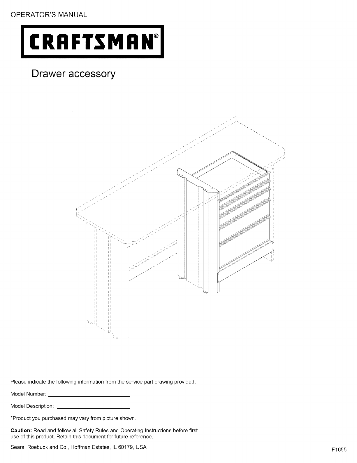
Drawer accessory
I
i I
I
I
I
i I
I
I
Please indicate the following information from the service part drawing provided.
Model Number:
Model Description:
*Product you purchased may vary from picture shown.
Caution: Read and follow all Safety Rules and Operating Instructions before first
use of this product. Retain this document for future reference.
Sears, Roebuck and Co., Hoffman Estates, IL 60179, USA
F1655
f
SAFETY WARNINGS AND CAUTIONS:
• Use appropriate safety equipment when using power and hand tools. Failure to do so may cause personal injury or product
damage.
• Use adequate manpower when assembling and moving this unit. Failure to do so may cause personal injury or product
damage.
• DO NOT stand on this product. You may fall which may cause personal injury.
• DO NOT mount this product on a truck bed or any other moving object. This may cause personal injury or product damage.
• Appropriately secure this product before moving it with a forklift.
• DO NOT alter this product in any manner. For example, do not weld external Iockbars or attach electrical equipment. This
may cause product damage or personal injury.
• Keep the product on level surfaces. The product may become unstable and tip if stored or moved on an un-level surface,
which may cause personal injury or product damage.
• BE CAREFUL when opening more than one drawer. The product may become unstable and tip, which may cause personal
injury or product damage.
• DO NOT step in the drawers. You may fall which may cause personal injury.
• Maximum weight for each drawer should be no more than (35) pounds.
k,.
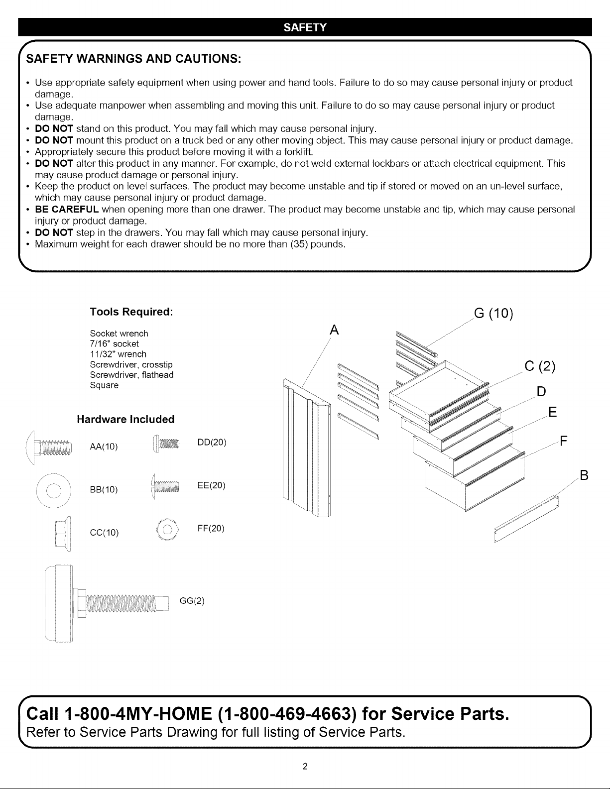
Tools Required:
Socket wrench
7/16" socket
11/32" wrench
Screwdriver, crosstip
Screwdriver, flathead
Square
Hardware Included
AA(10)
,,m
BB(10)
cc(10)
'i
.)
G (10)
A
/
/J
/
DD(20)
EE(20)
FF(20)
GG(2)
ii
Call 1-800-4MY-HOME (1-800-469-4663) for Service Parts.
efer to Service Parts Drawing for full listing of Service Parts.
f
r
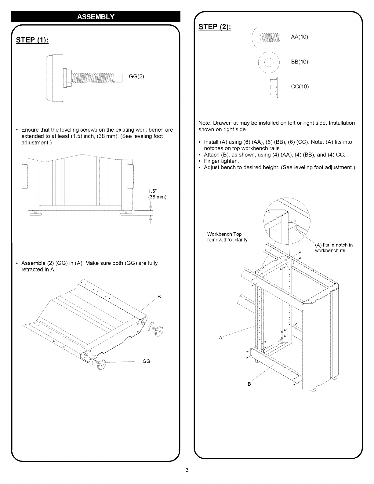
STEP (1):
GG(2)
I
Ensure that the leveling screws on the existing work bench are
extended to at least (1.5) inch, (38 mm). (See leveling foot
adjustment.)
1.5"
(38 mm)
STEP (2):
AA(10)
"\ i
BB(10)
/
CC(10)
Note: Drawer kit may be installed on left or right side. Installation
shown on right side.
• Install (A) using (6) (AA), (6) (BB), (6) (CC). Note: (A) fits into
notches on top workbench rails.
• Attach (B), as shown, using (4) (AA), (4) (BB), and (4) CC.
• Finger tighten.
• Adjust bench to desired height. (See leveling foot adjustment.)
• Assemble (2) (GG) in (A). Make sure both (GG) are fully
retracted in A.
Workbench Top
removed for clarity
(A) fits in notch in
workbench rail
B
_11111
.)
r
f
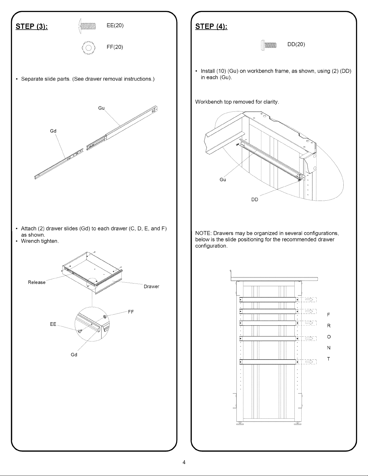
STEP (3):
• Separate slide parts. (See drawer removal instructions.)
EE(20)
FF(20)
Gu
Gd
STEP (4):
DD(20)
• Install (10) (Gu) on workbench frame, as shown, using (2) (DD)
in each (Gu).
Workbench top removed for clarity.
• Attach (2) drawer slides (Gd) to each drawer (C, D, E, and F)
as shown.
• Wrench tighten.
Release
.........FF
Drawer
EE i_ .....
/
/
/
Gd
NOTE: Drawers may be organized in several configurations,
below is the slide positioning for the recommended drawer
configuration.
...... ii
F
R
0
N
T
,.)
 Loading...