

Page 1
owner's
manual
MODEL NO.
636.796912
CAUTION:
Read Rules for
Safe Operation
and Instructions
Carefully
êêl9501201
8619S01201 r/88
CRAFTSMAN
37.7 cc GAS POWER BLOWER
® Assembly ® Maintenance
® Operation «Repair Parts
Sears, Roebuck and Co., Chicago, III 60684 U.S.A.
PRINTED IN JAPAN
Page 2

TWO YEAR LIMITED WARRANTY ON CRAFTSMAN
POWER BLOWER 636.796912
For tvvo years from date of purchase, when this POWER BLOWER is maintained, lubricated, and tuned up according to
the operating and mainlenance instructions in the owner's manual, Sears will repair free of charge any defect in material or
workmanship.
This warranty excludes blower pipes, spark plug, and air cleaner: which are expendable pans and become worn during
normal USB.
If this POWER SLOWER is used for commercial or rental purposes, this warranty applies for only 30 days from the date
of purchasa.
WARRANTY SERVICE IS AVAILABLE BY CONTACTING THE NEAREST SEARS SERVICE CENTER/DEPARTMENT IN THE UNITED STATES, This warranty applies only while this product is in use in the United States,
This warranty gives you specific legal rights, and you may also have other rights which very from state to state.
SEARS, ROEBUCK AND CO.
DEPT. 698/731A
SEARS TOWER
CHICAGO, ILLINOIS 60684
,4|li
INTRODUCTION
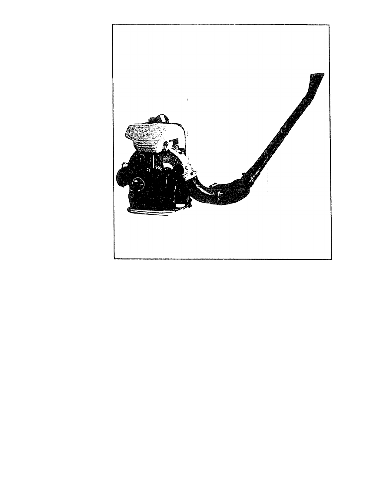
The Sears Power Blower, Mode! 636.796912 is a lightweight, high performance 2 cycle two stroke,
gasoline powered blower, which is designed for autumn leaves, driveway and sidewalk sweeping, gutter
cleaning, light snow and debris removal. The blower works faster and more efficiently than rakes or
brooms. Excellent balance, a vibration damping system and light weight ensure comfortable, safe
and fatigue-free operation.
This manual provides instructions for assembly, operation and maintenance for your unit. Be sure to
read this manual before operation.
IMPORTANT
RULES FOR SAFE OPERATION
1. Gasoline
(1) Handle gasoline with care. It is high inflammable.
(2) Use proper gasoline-oil fuel mixture. See P. 4.
(3) Refuel before starting work.
(4) Do not refuel a hot engine.
{5} Avoid spilling fuel or oil. Always wipe unit dry before using.
(6) Move at least 3 meters (10 feet) away from the fueling point before starting engine.
(7) Always store gasoline in approved container.
2. Operation
(1) Do not operate in unventilated area,
(2) Do not allow bystanders in work area.
{35 Always wear light clothing.
Page 3

{4) Aiways wear safety glasses and a face filter mask.
Wear ear protectors where possible.
{5} Do not touch muffler, spark plug and rotating parts,
(6) Do not run the machine without flexible corrugated pipe and spent pipe or the engine
may be damaged,
(7) Do not use the machine in such a way that the end of spout pipe may be covered,
Check
ns Aiways check periodically for efficient and safe operation.
(2) Before Storing, drain fuel tank and carburetor.
(3) Wash air cleaner element with neutral detergent and dry it well.
(4) Remove dust from blower.
(5) Tighten bolts further if they are loose.
(6) Replace damaged parts.
(7) Always use proper parts for replacement.
SECTION i.
SECTION II,
SECTION ill.
SECTION IV,
SECTION V.
SECTION VI.
SECTION Vtl.
SECTION Vlil.
SECTION IX.
SECTION X.
SECTION XI.
TABLE OF CONTENTS
TECHNICAL SPECIFICATIONS ..........................
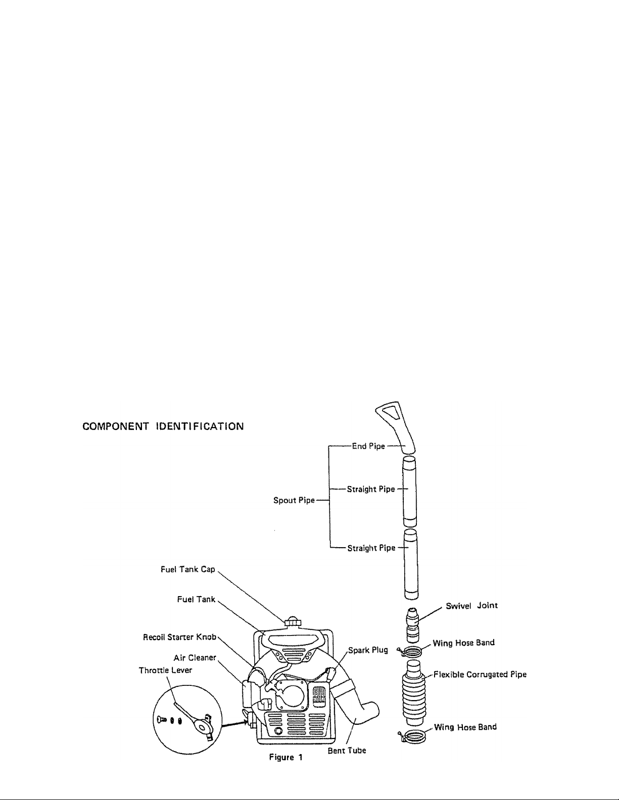
COMPONENT IDENTIFICATION
......................
ASSEMBLY INSTRUCTIONS.............................
PREPARATION FOR USE
STARTING THE ENGINE
STOPPING THE ENGINE
...........................
..
...................................
.......
..........................
OPERATING THE POWER BLOWER ....
CHECK AND MAINTENANCE
...........................
STORAGE AFTER USE......................................
TROUBLESHOOTING , .,
SPARE PARTS LIST ...
........
................. . . . .
....................
...............................
.
..................................................... 4
..
.................
.
. 4
................................................. . 5
.
..................................................... 5
.............
........................................ 5
...................................................... 6
...........................................................
.
..................................................
. 6
...................................................... 7
.
..................................................... a
......................................................10
Page
6
Page 4
TECHNICAL SPECIFICATIONS Mode! 636.796912
Dimensions :
Weight, dry ;
Fuel capacity ;
Engine Type :
Displacement :
Ignition system ;
Carburetor ;
Spark plug ;
Spark plug gap :
Starter ;
Max. air volume :
Max. air speed :
Muffler :
Fuel :
*Specifications are subject to change without notice.
LxWxH = 450x490x495mmf17.7 in. x 19.3 in.x 19.5 in.)
8 kg !17.6 lbs.)
2.4 litre iO.634 gal.)
Air cooled two stroke
37.7 cc {2.3 cu.in.)
Solid State ignition
Float type
S.T.D. 360942
0.6-0.7 mm (.024 - .028")
Automatic recoil
11 m^/min. (385 cu.ft./min.)
83 m/sec. (273 ft/sec.)
Spark arrester
Fuel-Oil Mix Between 20 and 25 to 1
For the first twenty hours, use the mixing ratio of between 15
and 20 to 1
Page 5
m. ASSEMBLY INSTRUCTIONS
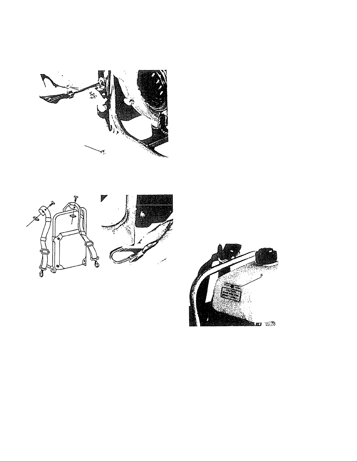
1. Attach throttle lever to the machine. (Fig, 2)
Note; Ensure that the lever can be operated normally.
Screw
Figure 2
2, Attach shoulder straps to the machine. (Fig, 3}
Note: Adjust the straps to fit your body.
WARNING; Experience indicates that alcohol blended fuels
icalled gasohol or using ethanol or methanol) can attract
moisture which leads to separation and formation of acids
during storage. Acidic gas can damage the fuel system of an
engine while in storage.
To avoid engine problems, the fuel system should be emptied
before storage for 30 days or longer Drain the gas tank, start
the engine and let it run until the fuel lines and carburetor
are empty. Use fresh fuel next season. See Storage Instructions
for additional information.
Never use engine or carburetor cleaner products in the fuel
tank or permanent damage may occur,
CAUTION:
• When preparing fuel mixture, mix only the amount
needed for the job you are to do Do not use fuel mixture
that has been stored longer than two (2) months. Fuel
mixture stored lortger than this will cause hard starting
and poor performance, if fuel mix has been stored
longer than this time it should be removed and filled
with a fresh mixture.
• Use only a good grade of regular gasoline,
0 Use only a reputable brand of 2-cycle, air cooled engine
oil. Sears Chain Saw Oil is especially suited to this
engine,
• For the first twenty hours, use the mixing ratio of be
tween 15 and 20 to 1
Figure 3
3. Assemble blower pipes, (Fig, 1)
Note: Assemble pipes securely or they may separate
. while operating.
IV. PREPARATION FOR USE
1, Ensure again that all parts are assembled normally and
that all nuts and bolts are properly tightened
2. Adjust shoulder straps to fit your body so that pads rest
comfortably on your shoulder or you will be tired
3 Fuel and oil mixing
(1) Mixing ratio of fuel and oil: 20— 25:1
Example; 20 : 1 = gasoline 1 gal, : oil 7 oz,
25 : 1 = gasoline 1 gal, : oil 6 oz
(2) Pour half the gasoline into the container, add oil and
shake to ensure thorough mixing. Now add the
remainder of gasoline and shake again
Fill the tank with fuel without spilling.
4.
i1) Do not fill fuel above fuel limit level. (Fig. 4)
(2) Wipe all spilled fuel with a dry cloth,
(3) Always attach the fuel strainer, (Fig, 11)
(4) Tighten fuel cap securely,
uei limit level
Figure 4
V. STARTING THE ENGINE (Fig. 5 & 6)
1. Open fuel cock, (Fig 5)
2, Close choke Sever, (Fig. 5)
Note; In winter, close fully, but in summer or when the
engine is warm, open partly or fully.
Page 6
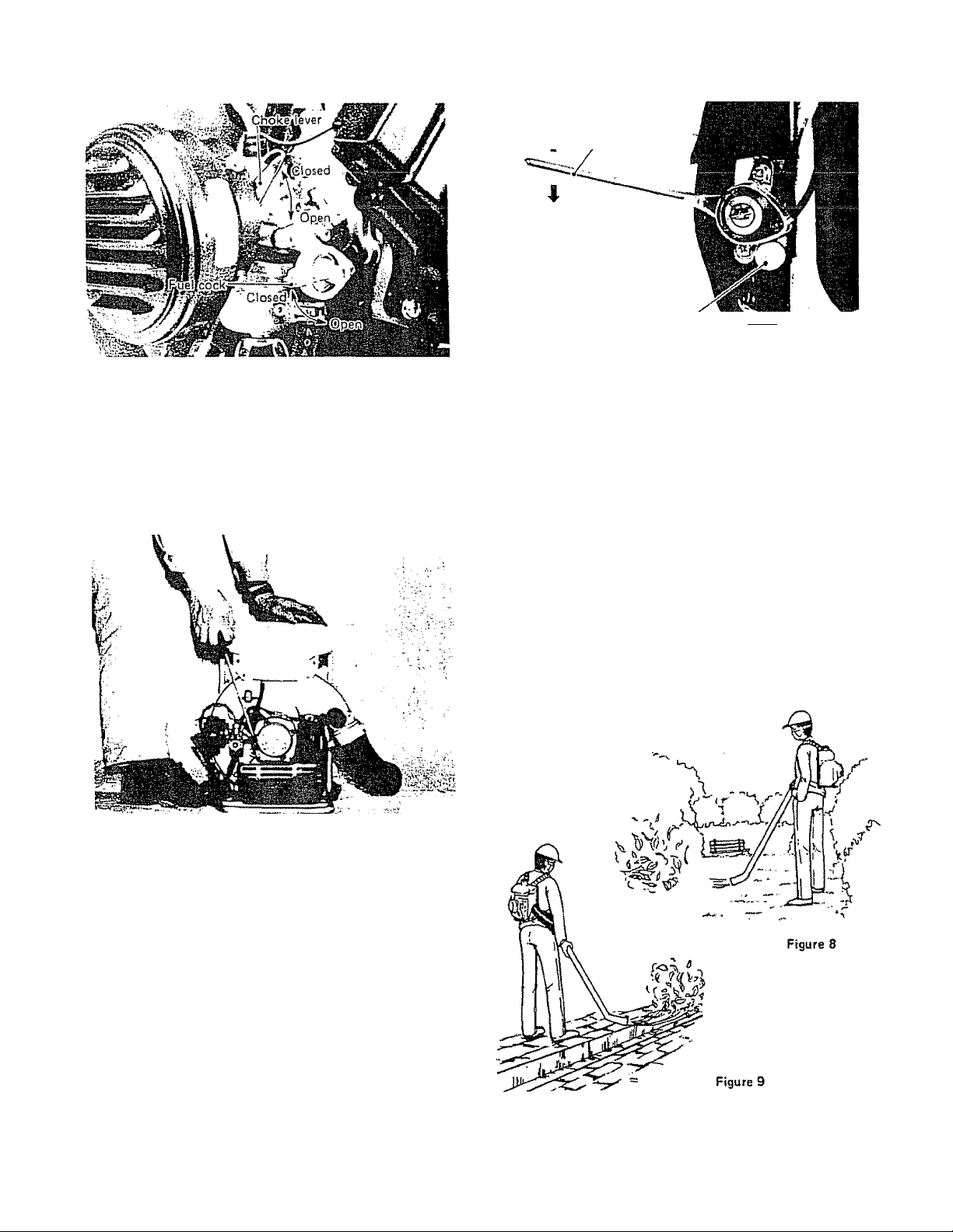
Figure S
3. Push up throttle lever, (Fig. 7)
4. Holding the machine by your left hand and putting your
left foot on the machine frame, give a strong and straight
pull to recoil starter by your right hand. (Fig. 6j
CAUTION
Do not pull off rope, but return it gently with care.
UP (Highspeed)
“I“ Throttle lever
DOWN (Low speed)
StQPTOtfoffllM^ ’
Figure 7
VII. OPERATING THE POWER BLOWER
1, Adjust shoulder straps correctly to make the machine fit
your body .
2, After the engine fires, put the machine on your back
without inclining.
3. The velocity of air stream can be controlled from a gentle
breeze to a high-speed blast by throttle lever,
4. Select the best speed for each application of the blower.
Example: low speed for blowing dry leaves from lawn
and high speed for moving gravel or dirt from
driveway, (Fig. 8 & 9)
Figure 6
5. After the engine fires, open choke lever gradually to re
duce engine speed
6, Warm up the engine at tow speed
Note; winter: about 5 min. summer: 2 — 3 min.
VI. STOPPING THE ENGINE
1, Push down throttle lever to reduce engine speed.
2, Stop the engine by pushing stop button. (Fig. 7)
3, Put the machine down on the ground and close fuel cock.
CAUTION
о Do not point the blower pipe in the direction of people
or animals.
• Always wear safety glasses and use-a dust mask,
e Do not operate in unventilated area.
Page 7

VIH. CHECK AND MAINTENANCE
1. Air cleaner (Fig. 10)
(1) Remove air cleaner cover and take out air filter.
(2) Accumuiated dust on the air filter will reduce engine
efficiency and increase fuel consumption,
{3} Wash air filter and dry it wetl,
CAUTION
Do not use gasoline and inflammable solvent to clean the
filter.
Air cleaner case
Air filter
Carburetor (Fig. 13)
4,
(1) Carburetor has been correctly adjusted at the factory
for optimum performance.
To adjust idling speed, turn the throttle stop screw
(2)
(turning it clockwise increases engine speed and
turning it counterclockwise reduces the speed).
Idling speed must be adjusted to me minimum
(3)
constant speed.
Figure 10
Fuel strainer (Fig, 11)
(1) Fuel tank is fitted with a fuel strainer located under
filler cap- Do not remove this strainer when filling
the tank.
(2) The strainer should be removed and cleaned at
regular intervals.
Fuel tank cap
'Fuel strainer
-Packing B
Figure 11
3, Spark plug (Fig. 12)
(1) Clean or replace the piug if fouled with oily black
deposits,
(2) Replace the plug if the center electrode is rounded
at the end or if the ground electrode is worn,
(3) Adjust the gap 0,6 — 07 mm ( 024 — ,028").
B, MUFFLER AND EXHAUST PORT (Fig. 14)
in the event that the engine should lose power and overheat,
the muffler should be removed and checked for excessive
deposits. Carbon build up in the exhaust port should be
removed with a piece of wood, removing that particles of
carbon deposits from the muffler flange area and wash the
complete unit in a suitable solvent.
Spark arrester
Screw
Figure 14
Page 8

IX. STORAGE AFTER USE
5. Store the unit in a dry atmosphere and keep out dust.
1, Correctly preparing your Sears Power Blower for extend
ed storage will be amply rewarded by an increased service
life and trouble-free performance,,
2 Drain fuel tank and carburetor thoroughly,
Drain carburetor through drain cock,
3, Remove spark plug, pour one teaspoon of engine oil into
cylinder and pull recoil starter gently to distribute the
oil. Replace spark plug securely.
4. Thoroughly clean the unit and coat unprotected surfaces
with oil to prevent rust.
K TROUBLE SHOOTING
Refer to the chart to locate the problem and take the appropriate action.
Table 1
Fuel is not
reaching Fuel line hose clogged „ Clean.
carburetor
Fuel is not
— reaching -------------—^
cylinder
6
c
О I
Z ^
Ignition coil
-in goodcondition
It is important to prevent gum deposits from forming in
essentia! fuel system parts such as the carburetor, fuel filter,
fuel hose^ or tank during storage. Also, experience indicates
that alcohol blended fuels {called gasohol or using ethanol or
methanoll can attract moisture which leads to separation and
formation of acids during storage. Acidic gas can damage the
fuel system of an engine while in storage.
To avoid engine problems, the fuel system should be emptied
before storage of 30 days or longer. Follow these instructions:
1
___ PisTon.& cytinder worn..,..
-----
Strainer dogged
i
-----
Carburetor out of order ,
, Wire connection defective .
High-tension cord
‘ connection defective
...........
...... Replace,
Clean.
Disassembie and check.
Heconnect
Repair as necessary.
.
Ш
’ ti
LI,
R
-No spark at plug -
X
ti
« c
X «
Û-0
«
Э
- c
о a
a
x: K
¡r 2
-If
. «
a
a
x:
H
Li
о
a
* w
Fuel does
not keep
funning
Accelera
tion and
low speed function
defective
Carburetor _
overflow
Engine does
' not crank *
. Insulator cracked
. Spark gap incorrect.
. Covered with carbon
, Fouled with fuel
Starting procedures
■ incorrect
Fuel valve clogged with
dust .............
Fuel passage in carburetor
clogged with dust
□
Fuel leaking from fixing
■ surfaces of carburetor
Carburetor does
■ not work normally
Crankcase and cylinder
‘ pressure leaks
Fuel inlet needle valve
- clogged with dust
Exhaust pipe sticky
■ with fuel
. Searing damaged ,
■ Piston and cvlirtder seized.
, Crankshaft worn
’ crankcase
......................
..................................
......................
....................
Crankshaft contacting
.
.................
_____
, Replace plug.
, Adjust.
, Clears or replace.
. Clean or replace.
. Start correctly
. Clean,
. Disassemble and replace
, Retighten.
, Replace,
.........
................................................
.. Stop leakage,
.
.. Clean.
This is because fuel mixture
is too rich,
■ Start the engine several times
with choke lever fully open.
_____
, Disassemble and replace
. Disassemble and replace,
. Disassemble and replace,
, Disassemble and replace,
Page 9

Table 2
3
U»
.£
•o a
n
c
'm
c
m
. Engine
overheatsd
. Firing function.
defective
, Carburetor _
defective
_ Other
troubles
Improper fuel, used
Spark plug defectiva
' ibumt!
............
..............
As cooling fins dog, air
' does not pass well '
Excessive deposits itt
■ combustion chamber
. Plug damaged or fouled..,,...... Replace or clean.
Combustion poor due to , . .
defective wiring ’
Needle setting
'incorrect
Carburetor overflow
. Air cleaner dogged
Compression insufficient
(piston ring stuck or
worn out)
Cylinder chrome plating
' peeled or worn out ......................
Exhaust port dogged with
' carbon
Throttle is not fully
’ open
Mvui Check wiring,
................
..
...........
...
..........
..............
.................................
Use fuel with correct mixing ratio,
' ' Never use gasoline of poor quality.
...... Replace.
.
..... Clean fins,
....... Disassemble and remove carbon.
Readjust,,
........ Refer to Table 1,
Clean as necessary.
Disassemble, check and replace
, if necessary.
. Replace cylinder,
. Clean as necessary.
.
, Readjust,
Page 10

SEARS POWER BLOWER PARTS LIST - MODEL 636.796912
Figure 15
Page 11

SEARS POWER BLOWER PARTS LIST • MODEL 636.796912
Figure 15
KEY
NO.
1
2
3
4
S
6
7 NF04S-11Ì4 1
8
9
to
11
12
13
16
17
18
19
20
21
22
23
24 00218 0500 Q
25
26
27
28
29
30
31
32
33
34
35
36
37
38
39
PART
NO.
NF04S-01S0A 1
NFQ4S-1101-RB
NF04S.1102-RB
NF04S-1104F 1
NF04S-1107A 2
FL40-1109B-PB 1
NF04S.11I5
FH04S-1104
Ft40-1110
0420 22938 0
FL40-201IA-RB
FL40-2012A 1
NF40.2101A 2
EC024Ì83 1
EC02Ì44
FL40-3101A
FL40<S102
FL40-5011
FL40-5012
EC02-720
00113 0618 0
00165 0612 0 3
00218 0600 0
00218 1000 0
00227 0400 0
00310 0500 0
00311 0600 0
00311 1000 0
00312 0500 0
00312 0600 0
00320 0400 0
00320 0500 0 2
00320 0600 0 10
00320 1000 0
00431 0514 0
G0431 0512 0
00435 0518 0
QTY.
1
1
1
4
. 9
1
1 Nut (M4l
4
DESCRIPTION
Muffier mounting plate ass'y
1
1 Volute ease {rear!
!
1
1
1
1
1
1
1
5
8
1
4
4
1
1
4
1
7
Volute case {fronti
Bent tube
Screw (MS X 671
Engine cover
Impeller spacer
Cover
Plug
Impeller
Plug ¡rubberl
Frame compì.
Shoulder pad compì.
Vibrailon^jroof rubber
Fuel tank cap ass'y (Incl. 161
Packing A
Fuel tattk
Fuel-line hose
Throttle lever
Throttle ^Ire
■Stoptiution
Boll ÌM5 X 18!
Bolt (M6 X 12!
Nut |M5)
Nut ÌM6!
Nui^iM10)_3
Washer (M51
Washer (M61
Washer (MIO!
Washer !M51
Washer {MB!
Spring washer {M4!
Spring washer (M51
Spring washer <M6i
Spring washer {MIDI
Screw (pan head! (MS x 14!
Screw (pan head! (M5 x 12!
Screw ass'y (M5 x 18!
KEY
NO.
40 00431 0610 0
41
42 00626 3085 0
43 EC03-6103
44 ,
45
46
47
48 .
49
SO
51
52
PART
NO.
00431 0616 0
FL40-3103
FL40-9106
0561 13998 2
0641 27999 0
ECOSA-6111
HS021I-2028-RB
NB30K-6103 2
PS03-5111
00436 0512 0
QTY.
2
4
1 0 ring
1
1
1
2
1
1
2
1
I
DESCRIPTION
Screw (pan head! (M6 x 10!
Screw (pan head! (M6 x 16!
Fuel-line hose proieeiion tube
Plate
Labe!
Clamp (Hose! __
Fuel strainer
Packing
Plate
VibratiQO-proof rubber
Plug (rubberl
Screw ass'y
Page 12

SEARS POWER BLOWER PARTS LIST-MODEL 636.796912
Figure 18
Page 13

SEARS POWER BLOWER PARTS LIST - MODEL 636.796912
Figure 16
KEY
NO.
20
21
22
23
24
25
26
27
28
29
30
31
32
33
34
35
36
37
38
39
PART
NO.
1
2
3
4
S
6
7
8
9
10
11
12
13
14
15
16
17
18
19
EC044J72
0440 12999 J
0440 15997 1
060015988 0 2
EC034)71
0119 05994 0
0105 06934 0 6
EC044)125
EC03-109A
EC044191A
eC04-104c
eCQ3-115
0119 05995 0
EC04TÌ222
EC04-206/2B
EC04-207A
6C04-210A
0565 11999 0
0610 12996 1
EC0441516A
EC04-0S13A
A50103212700
243051821009
451050800009
A54103200100
A55003210001
A600032000QO
A60102600000
A56002600291
141051251002
A60S03210000
A57120950000
QTY.
1
1
1
4
1
1
1
1
2
4
1
1
1
2
2
1
1
1
1
4
4 Washer (M5)
1
1
1
1
1
1
1 Return spring
1
A57202700QOD 1
EC0443378
EC04-3122
00433 0520 0
FL40-9105/2A
1
1
3
1
EC044)71BA 1
11100100100
DESCRIPTION
Crank case ass'v (Ind. 2 ihru 7)
Oil seal (fronif
Oil seal iresri
Ball bearing
Crank case packing
Ì
Boll isockei head} (MB x 30}
Stud (M6)
Cylinder compì, (incl. 7)
Cylinder packing
Reed ass'v
Carburetor bracket
Reed bracket packing
Bolt (socket head! (MS x 18)
Crank shaft ass'v
Piston
Piston pin
Piston ring
Clip
Needle bearing
Recoil starter compì. (Incl. 21 thro24i
Recoil starter ass'v iincl. 25 ihru33)
Starter case B
Serev» IMS X 18}
Reel
Ratchet
Spiral spring
Friction spring
Friction plate
Bind screw (M5 x 12)
Starter rope
Starter knob
Mufller compì.
Mu!((or gasket
Screw ass'v (M5 X 20)
Label (model)
Magneto compì. (Incl. 39, 401
t
Flywheel
KEY
NO.
40
41
42
43
44
45 -
46
47
48
49
50
51
52
53
54 EC044)379ATA
55
56
PART
NO.
QTY.
11400331000
KM614388C
0650 14995 0
0170 08996 0
0203 08999 0
00218 0500 0
00310 OBOO 0
00320 0600 0 6
00434 0420 0
00532 0310 0
0566 05998 0
00310 0S00 0 1
0CM31 0510 0
00S32 0320 0
0043104100
0022704000
DESCRIPTION
1 Ignition coil
1
1
1
1
Plug cap
Spark plug
Nut (left) (MB)
Spring washer (M8)
6 Nut (M6)
1 Washer (M8)
Spring washer (M6)
2
1
1
Screw ass'v (M4 x 20)
Woodrulf key
Clamp
Washer (M5)
1
1
1
Screw (pan head) (M5 x 101
WoodruH key
Spark arrester
1 Screw (pan head) (M4 x 10)
1
Nut (M4)
Page 14

SEARS POWER BLOWER PARTS LIST-MODEL 636.796912
Figure 17
Page 15

SEARS POWER BLOWER PARTS LIST - MODEL 636.796912
Figure 17
KEY PART
NO.
1
2
3
A
5
6
7
a
9
^10
n
12
13
14 VM15/173
15
16
17
18
19
20
21
22
23
24
25
26
27
28
29
30
31
32
33
34
35
36
EC04-0682A 1
CK/31
832-16001
J8-3N05
MD14/40
VM14c1/38tJ
VM1S/24A
VM16/200
VM12/43
MD13/44
M21/15
VM24/148
N102-221
VMl 5/353
VM1S/264
VMl 5/351
VM13/139
BS2-00031
EC03-S0010
VM13/68A
VM13/326
82=43630
B34/83
VM13/215
VMl 5/331
VM18/164A
CW2»0416
VMl 5/348
VM13/210
CW2-0414
EC044)335B
0736 36998 0
00436 0410 0
EC04-3304A
EC04-3305
NO.
QTY.
1
1
1
1
1
1
1
1 Cap
1
1
1
1
1 Needle ass'y
1
1
1
1
1
1
1
1
1
1
1 Nut
1
1
2
1
1
2
1
1
4
1
2
DESCRIPTION
Carburetor compì. Unci. 2 !hni 31}
Cock body ass'y
Piston waive {#T.0i
Jet needle
E nng
Spring seat
Spring
Top
Cable guide
Cable gdjuster lock nut
Cable adjuster
Mam let (#77.51
Float arm
Float pin
Gasket
Float
Float chamber body
Guide screw ass'y
O ring
Clip
Bolt
Washer
Spring
Throttle stop screw
Spring washer cross screw
Gasket
Filter
Spring washer cross screw
Air cleaner ass'y Unci, 33,35, 361
Label
Screw ass'y (M4 x 10}
Air cleaner cap
Element
Page 16

SEARS POWER BLOWER PARTS LIST - MODEL 636.796912
Figure 18
Page 17

SEARS POWER BLOWER PARTS LIST - MODEL 636.796912
Figure 18
KEY
NO.
!
2
3
4
5
6
7
8
9
10
11
12
13 0715 06999 0
14 0713 21999 0
15
PART
NO.
NF04S-0903/1
FL40-9001
NF31-097B
NF04S-9121
FL40-9120
FL40-9121
NF40-7120
FL40-9012
FL40-9014
0717 04999 0
6619501201
0700 00994 0
0710 08999 0
QTY.
1
1
1
1
1
1
1
1
1
DESCRIPTION
Wing hose band (big!
Shoulder band ass'v
Wing hose band
Corrugated pipe
2
1
1
1 Plus driver
1
1
Straight pipe
End pipe
Hoso ctarop
Swivel joint
Tool kit {tncl.10,12 throlSi
Wrench Isocket head)
Owner's manual |FL40-9107/4i
Tool bag
Box wrenchS21 M/M)
Double-end wrench (8 x 10 M/Ml
Page 18

OWNER^S
MANUAL
SEARS POWER BLOWER
The model number of your power blower is
located on the label on recoil starter of the
engine.
The serial number of your power blower is
located on the label on the fan housing.
MODEL NO.
636.796912
HOW TO ORDER
REPAIR PARTS
2.
When ordering repair parts, always give the
following information:
(1) IVJodel number:
{2) Name of item:
{3) Part number
(4) Part description
All parts listed may be ordered from any Sears
Service Center or most Sears stores.
(1) If the parts you need are not stocked
locally, your order wilt be electronically
transmitted to a Sears Repair Parts Distri
bution Center for handling.
636.796912
37.7 ccGAS POWER
BLOWER
6619501201 Sold by Sears, Roebuck and Co., Chicago, IL60684 U.S.A. Printed in Japan
 Loading...