

Craftsman 536772360 Owner’s Manual
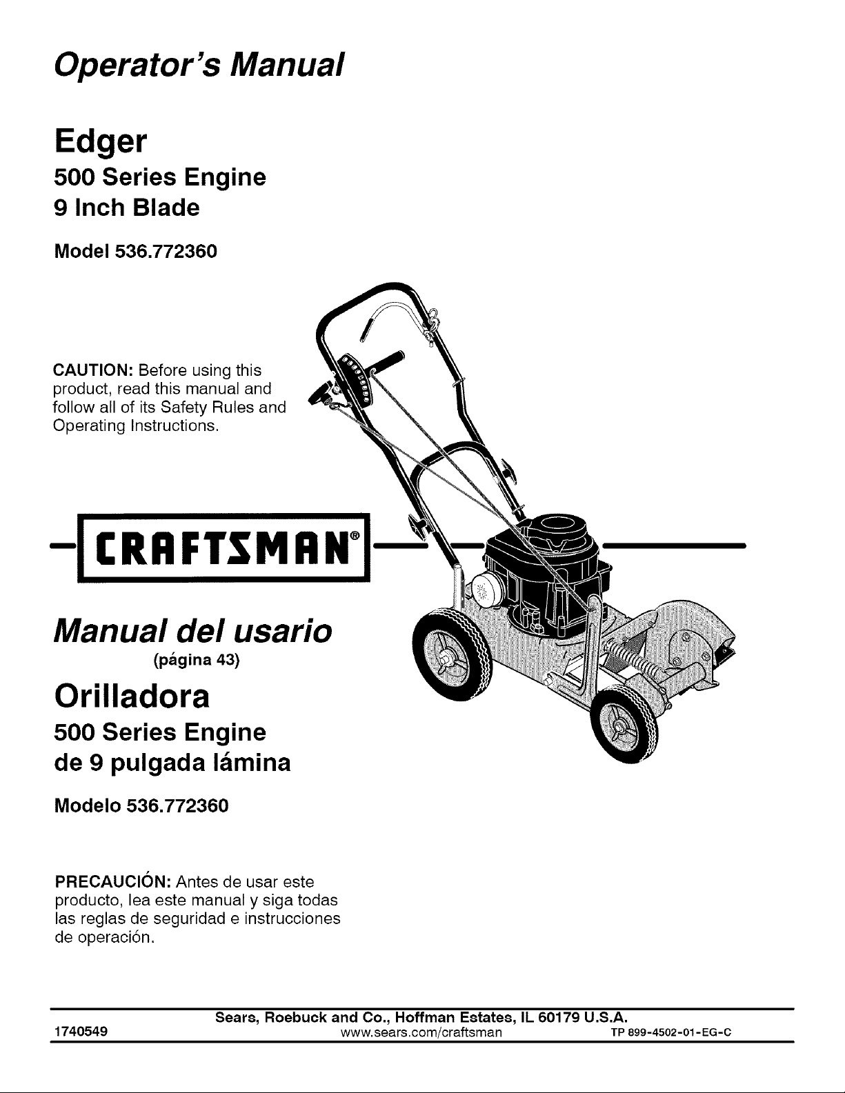
Operator's Manual
Edger
500 Series Engine
9 Inch Blade
Model 536.772360
CAUTION: Before using this
product, read this manual and
follow all of its Safety Rules and
Operating Instructions.
-IcR"FTS"""°l-
Manual del usario
(pagina 43)
Orilladora
500 Series Engine
de 9 pulgada lamina
Modelo 536.772360
PRECAUCION: Antes de usar este
producto, lea este manual y siga todas
las reglas de seguridad e instrucciones
de operaci6n.
Sears, Roebuck and Co., Hoffman Estates, IL 60179 U.S.A.
1740549 www, sears,com/craftsman TP899-4502-01- EG-C
Craftsman Edger Warranty ......... 2
Edging Tips ............................ 18
Operator Safety ................... 3
Symbols And Warnings ............ 3
Operator Safety Rules ................... 6
Assembly ......................... 8
Parts Packed Separately In Carton ........ 8
Removal From The Carton ............... 8
How To Raise The Handle ................ 9
Features .......................... 10
Operation ......................... 11
Before Starting The Engine ............... 11
HowTo Start The Engine ................. 13
How To Stop ........................... 14
How To Use The Depth Control Lever ...... 14
Maintenance ...................... 19
Maintenance Chart ..................... 19
Recommended Maintenance ............. 19
How To Remove The Belt ................ 20
How To Replace The Blade ............... 21
Engine Maintenance ..................... 22
Storage ................................ 25
Troubleshooting .................. 26
Product Specifications ............ 27
Power Ratings .......................... 27
Illustrated Parts List ............... 30
Edger ................................. 30
Engine ................................ 34
TWO YEAR FULL WARRANTY ON CRAFTSMAN EDGER
When assembled, operated and maintained according to all supplied instructions, if this
Craftsman Edger fails due to a defect in material or workmanship within two years from the
date of purchase, return it to any Sears store, Sears Parts & Repair Center, or other
Craftsman outlet in the United States for free repair (or replacement if repair proves
impossible). This warranty does not include Edger spark plugs, blades or belts, which are
expendable parts that can wear out from normal use in less than two years.
This warranty applies for only 90 days if this Edger is ever used for commercial or rental
purposes.
This warranty gives you specific rights, and you may also have other rights which vary from
state to state.
Sears, Roebuck and Co., Dept. 817WA, Hoffman Estates, tL 60179
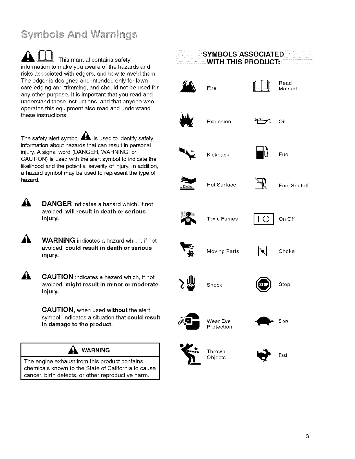
[[_ This manual contains safety
information to make you aware of the hazards and
risks associated with edgers, and how to avoid them.
The edger is designed and intended only for lawn
care edging and trimming, and should not be used for
any other purpose. It is important that you read and
understand these instructions, and that anyone who
operates this equipment also read and understand
these instructions.
WITH THIS PRODUCT:
Fire
Explosion _ Oil
[[_ Read
Manual
The safety alert symbol _ is used to identify safety
A
information about hazards that can result in personal
injury. A signal word (DANGER, WARNING, or
CAUTION) is used with the alert symbol to indicate the
likelihood and the potential severity of injury. In addition,
a hazard symbol may be used to represent the type of
hazard.
DANGER indicates a hazard which, if not
avoided, will result in death or serious
injury.
WARNING indicates a hazard which, if not
avoided, could result in death or serious
injury.
A
AI_ CAUTION indicates a hazard which, if not
avoided, might result in minor or moderate
injury.
_. Kickback ._ Fuel
,,_,l_II_l,_,,,Hot Surface ]_ Fuel Shutoff
Toxic Fumes Fi _ On Off
Movin0Parts I'1
Shock Stop
Choke
CAUTION, when used without the alert
symbol, indicates a situation that could result
in damage to the product.
_1_ WARNING
The engine exhaust from this product contains
chemicals known to the State of California to cause
cancer, birth defects, or other reproductive harm.
Wear Eye _ Slow
Protection
O_ Thrown
Objects
A
Fast
WARNING
WARNING
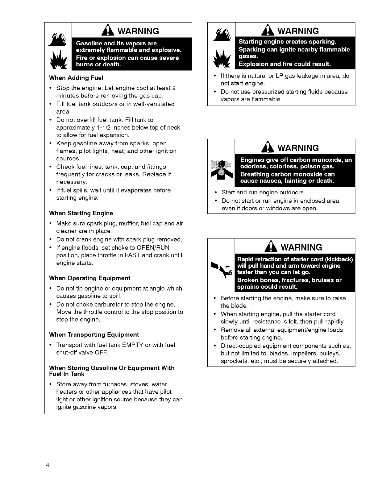
When Adding Fuel
• Stop the engine. Let engine cool at least 2
minutes before removing the gas cap.
• Fill fuel tank outdoors or in well-ventilated
area.
• Do not overfill fuel tank. Fill tank to
approximately 1-1/2 inches below top of neck
to allow for fuel expansion.
• Keep gasoline away from sparks, open
flames, pilot lights, heat, and other ignition
sources.
• Check fuel lines, tank, cap, and fittings
frequently for cracks or leaks. Replace if
necessary.
• If fuel spills, wait until it evaporates before
starting engine.
When Starting Engine
• Make sure spark plug, muffler, fuel cap and air
cleaner are in place.
• Do not crank engine with spark plug removed.
• If engine floods, set choke to OPEN/RUN
position, place throttle in FAST and crank until
engine starts.
• If there is natural or LP gas leakage in area, do
not start engine.
• Do not use pressurized starting fluids because
vapors are flammable.
WARNING
• Start and run engine outdoors.
• Do not start or run engine in enclosed area,
even if doors or windows are open.
WARNING
When Operating Equipment
• Do not tip engine or equipment at angle which
causes gasoline to spill.
• Do not choke carburetor to stop the engine.
Move the throttle control to the stop position to
stop the engine.
When Transporting Equipment
• Transport with fuel tank EMPTY or with fuel
shut-off valve OFF.
When Storing Gasoline Or Equipment With
Fuel In Tank
Store away from furnaces, stoves, water
heaters or other appliances that have pilot
light or other ignition source because they can
ignite gasoline vapors.
• Before starting the engine, make sure to raise
the blade.
• When starting engine, pull the starter cord
slowly until resistance is felt, then pull rapidly.
• Remove all external equipment/engine loads
before starting engine.
• Direct-coupled equipment components such as,
but not limited to, blades, impellers, pulleys,
sprockets, etc., must be securely attached.
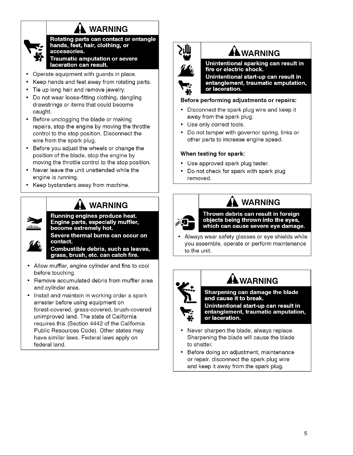
WARNING
• Operate equipment with guards in place.
• Keep hands and feet away from rotating parts.
• Tie up long hair and remove jewelry.
• Do not wear loose-fitting clothing, dangling
drawstrings or items that could become
caught.
• Before unclogging the blade or making
repairs, stop the engine by moving the throttle
control to the stop position. Disconnect the
wire from the spark plug.
• Before you adjust the wheels or change the
position of the blade, stop the engine by
moving the throttle control to the stop position.
• Never leave the unit unattended while the
engine is running.
• Keep bystanders away from machine.
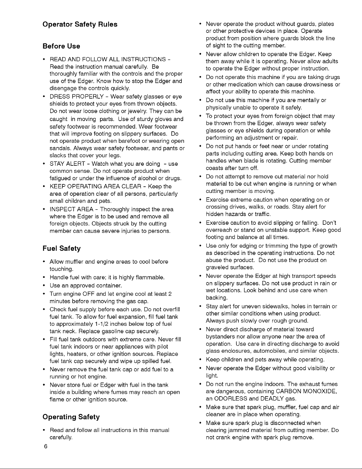
,WARNING
Before performing adjustments or repairs:
• Disconnect the spark plug wire and keep it
away from the spark plug.
• Use only correct tools.
• Do not tamper with governor spring, links or
other parts to increase engine speed.
When testing for spark:
• Use approved spark plug tester.
• Do not check for spark with spark plug
removed.
WARNING
) . = • = . _ =
It"i'T_'T'_ I_ [.I,.I..l!li.]h!
°Bl
_ I_ I--'-}-_o]dI _--,]i PlK_I (_!K_I-: l i l_,:-:- | _'_] I1 III ill
Allow muffler, engine cylinder and fins to cool
before touching.
Remove accumulated debris from muffler area
and cylinder area.
Install and maintain in working order a spark
arrester before using equipment on
forest-covered, grass-covered, brush-covered
unimproved land. The state of California
requires this (Section 4442 of the California
Public Resources Code). Other states may
have similar laws. Federal laws apply on
federal land.
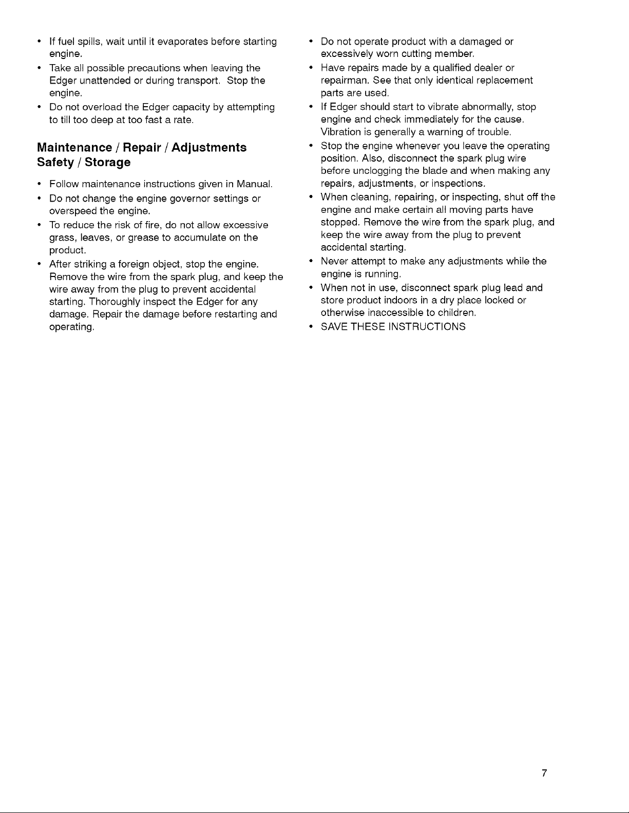
WARNING
• Always wear safety glasses or eye shields while
you assemble, operate or perform maintenance
to the unit.
, WARNING
• Never sharpen the blade, always replace.
Sharpening the blade will cause the blade
to shatter.
• Before doing an adjustment, maintenance
or repair, disconnect the spark plug wire
and keep it away from the spark plug.
Operator Safety Rules
Before Use
• READ AND FOLLOW ALL INSTRUCTIONS -
Read the instruction manual carefully. Be
thoroughly familiar with the controls and the proper
use of the Edger. Know how to stop the Edger and
disengage the controls quickly.
• DRESS PROPERLY - Wear safety glasses or eye
shields to protect your eyes from thrown objects.
Do not wear loose clothing or jewelry. They can be
caught in moving parts. Use of sturdy gloves and
safety footwear is recommended. Wear footwear
that will improve footing on slippery surfaces. Do
not operate product when barefoot or wearing open
sandals. Always wear safety footwear, and pants or
slacks that cover your legs.
• STAY ALERT - Watch what you are doing - use
common sense. Do not operate product when
fatigued or under the influence of alcohol or drugs.
• KEEP OPERATING AREA CLEAR - Keep the
area of operation clear of all persons, particularly
small children and pets.
• INSPECT AREA - Thoroughly inspect the area
where the Edger is to be used and remove all
foreign objects. Objects struck by the cutting
member can cause severe injuries to persons.
Fuel Safety
• Allow muffler and engine areas to cool before
touching.
• Handle fuel with care; it is highly flammable.
• Use an approved container.
• Turn engine OFF and let engine cool at least 2
minutes before removing the gas cap.
• Check fuel supply before each use. Do not overfill
fuel tank. To allow for fuel expansion, fill fuel tank
to approximately 1-1/2 inches below top of fuel
tank neck. Replace gasoline cap securely.
• Fill fuel tank outdoors with extreme care. Never fill
fuel tank indoors or near appliances with pilot
lights, heaters, or other ignition sources. Replace
fuel tank cap securely and wipe up spilled fuel.
• Never remove the fuel tank cap or add fuel to a
running or hot engine.
• Never store fuel or Edger with fuel in the tank
inside a building where fumes may reach an open
flame or other ignition source.
Operating Safety
• Read and follow all instructions in this manual
carefully.
6
• Never operate the product without guards, plates
or other protective devices in place. Operate
product from position where guards block the line
of sight to the cutting member.
• Never allow children to operate the Edger. Keep
them away while it is operating. Never allow adults
to operate the Edger without proper instruction.
• Do not operate this machine if you are taking drugs
or other medication which can cause drowsiness or
affect your ability to operate this machine.
• Do not use this machine if you are mentally or
physically unable to operate it safely.
• To protect your eyes from foreign object that may
be thrown from the Edger, always wear safety
glasses or eye shields during operation or while
performing an adjustment or repair.
• Do not put hands or feet near or under rotating
parts including cutting area. Keep both hands on
handles when blade is rotating. Cutting member
coasts after turn off.
• Do not attempt to remove cut material nor hold
material to be cut when engine is running or when
cutting member is moving.
• Exercise extreme caution when operating on or
crossing drives, walks, or roads. Stay alert for
hidden hazards or traffic.
• Exercise caution to avoid slipping or falling. Don't
overreach or stand on unstable support. Keep good
footing and balance at all times.
• Use only for edging or trimming the type of growth
as described in the operating instructions. Do not
abuse the product. Do not use the product on
graveled surfaces.
• Never operate the Edger at high transport speeds
on slippery surfaces. Do not use product in rain or
wet locations. Look behind and use care when
backing.
• Stay alert for uneven sidewalks, holes in terrain or
other similar conditions when using product.
Always push slowly over rough ground.
• Never direct discharge of material toward
bystanders nor allow anyone near the area of
operation. Use care in directing discharge to avoid
glass enclosures, automobiles, and similar objects.
• Keep children and pets away while operating.
• Never operate the Edger without good visibility or
light.
• Do not run the engine indoors. The exhaust fumes
are dangerous, containing CARBON MONOXIDE,
an ODORLESS and DEADLY gas.
• Make sure that spark plug, muffler, fuel cap and air
cleaner are in place when operating.
• Make sure spark plug is disconnected when
clearing jammed material from cutting member. Do
not crank engine with spark plug remove.
• Iffuelspills,waituntilitevaporatesbeforestarting
engine.
• Takeallpossibleprecautionswhenleavingthe
Edgerunattendedorduringtransport.Stopthe
engine.
• DonotoverloadtheEdgercapacitybyattempting
totilltoodeepattoofastarate.
Maintenance / Repair / Adjustments
Safety / Storage
• Follow maintenance instructions given in Manual.
• Do not change the engine governor settings or
overspeed the engine.
• To reduce the risk of fire, do not allow excessive
grass, leaves, or grease to accumulate on the
product.
• After striking a foreign object, stop the engine.
Remove the wire from the spark plug, and keep the
wire away from the plug to prevent accidental
starting. Thoroughly inspect the Edger for any
damage. Repair the damage before restarting and
operating.
• Do not operate product with a damaged or
excessively worn cutting member.
• Have repairs made by a qualified dealer or
repairman. See that only identical replacement
parts are used.
• If Edger should start to vibrate abnormally, stop
engine and check immediately for the cause.
Vibration is generally a warning of trouble.
• Stop the engine whenever you leave the operating
position. Also, disconnect the spark plug wire
before unclogging the blade and when making any
repairs, adjustments, or inspections.
• When cleaning, repairing, or inspecting, shut off the
engine and make certain all moving parts have
stopped. Remove the wire from the spark plug, and
keep the wire away from the plug to prevent
accidental starting.
• Never attempt to make any adjustments while the
engine is running.
• When not in use, disconnect spark plug lead and
store product indoors in a dry place locked or
otherwise inaccessible to children.
• SAVE THESE INSTRUCTIONS
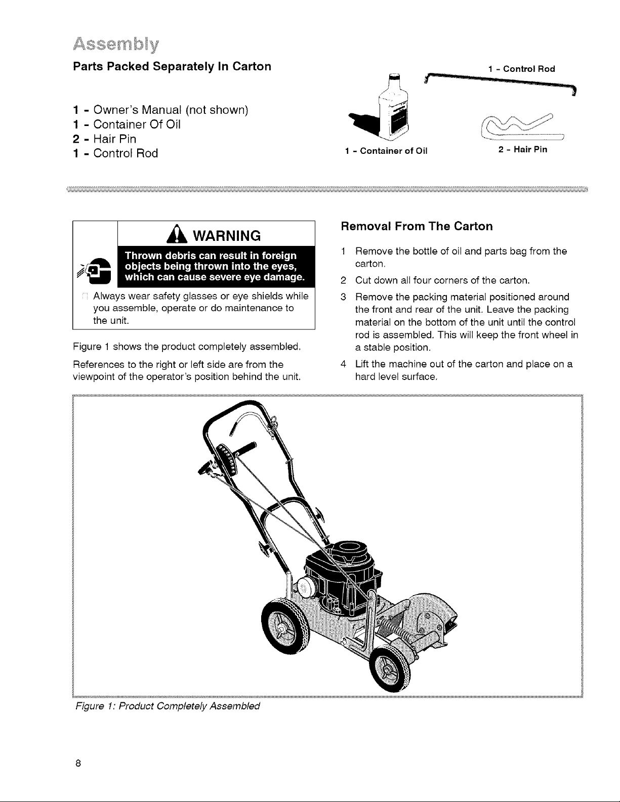
Parts Packed Separately In Carton
_--- /u I!
1 - Control Rod
L i
1 - Owner's Manual (not shown)
1 - Container Of Oil
2 - Hair Pin
1 - Control Rod
....:;:i,ii_il;;i;:i,ii_il;;i;:i,ii_il;;i;:i,ii_il;;i;:i,ii_il;;i;:i,ii_il;;i;:i,ii_il;;i;:i,ii_il;;i;:i,ii_il;;i;:i,ii_il;;i;:i,ii_il;;i;:i,ii_il;;i;:i,ii_il;;i;:i,ii_il;;i;:i,ii_il;;i;:i,ii_il;;i;:i,ii_il;;i;:i,ii_il;;i;:i,ii_il;;i;:i,ii_il;;i;:i,ii_il;;i;:i,ii_il;;i;:i,ii_il;;i;:i,ii_il;;i;:i,ii_il;;i;:i,ii_il;;i;:i,ii_il;;i;:i,ii_il;;i;:i,ii_il;;i;:i,ii_il;;i;:i,ii_il;;i;:i,ii_il;;i;:i,ii_il;;i;:i,ii_il;;i;:i,ii_il;;i;:i,ii_il;;i;:i,ii_il;;i;:i,ii_il;;i;:i,ii_il;;i;:i,ii_il;;i;:i,ii_il;;i;:i,ii_il;;i;:i,ii_il;;i;:i,ii_il;;i;:i,ii_il;;i;:i,ii_il;;i;:i,ii_il;;i;:i,ii_il;;i;:i,ii_il;;i;:i,ii_il;;i;:i,ii_il;;i;:i,ii_il;;i;:i,ii_il;;i;:i,ii_il;;i;:i,ii_il;;i;:i,ii_il;;i;:i,ii_il;;i;:i,ii_il;;i;:i,ii_il;;i;:i,ii_il;;i;:i,ii_il;;i;:i,ii_il;;i;:i,ii_il;;i;:i,ii_il;;i;:i,ii_il;;i;:i,ii_il;;i;:i,ii_il;;i;:i,ii_il;;i;:i,ii_il;;i;:i,ii_il;;i;:i,ii_il;;i;:i,ii_il;;i;:i,ii_il;;i;:i,ii_il;;i;:i,ii_il;;i;:i,ii_il;;i;:i,ii_il;;i;:i,ii_il;;i;:i,ii_il;;i;:i,ii_il;;i;:i,ii_il;;i;:i,ii_il;;i;:i,ii_il;;i;:i,ii_il;;i;:i,ii_il;;i;:i,ii_il;;i;:i,ii_il;;i;:i,ii_il;;i;:i,ii_il;;i;:i,ii_il;;i;:i,ii_il;;i;:i,ii_il;;i;:i,ii_il;;i;:i,ii_il;;i;:i,ii_il;;i;:i,ii_il;;i;:i,ii_il;;i;:i,ii_il;;i;:i,ii_il;;i;:i,ii_il;;i;:i,ii_il;;i;:i,ii_il;;i;:i,ii_il;;i;:i,ii_il;;i;:i,ii_il;;i;:i,ii_il;;i;:i,ii_il;;i;:i,ii_il;;i;:i,ii_il;;i;:i,i i_i_
1 - Container of Oil
2 - Hair Pin
Removal From The Carton
_1_ WARNING
1
Remove the bottle of oil and parts bag from the
carton.
2
Cut down all four corners of the carton.
Always wear safety glasses or eye shields while
you assemble, operate or do maintenance to
the unit,
Figure 1 shows the product completely assembled.
References to the right or left side are from the
viewpoint of the operator's position behind the unit.
3
Remove the packing material positioned around
the front and rear of the unit. Leave the packing
material on the bottom of the unit until the control
rod is assembled. This will keep the front wheel in
a stable position.
Lift the machine out of the carton and place on a
hard level surface,
Figure 1: Product Completely Assembled
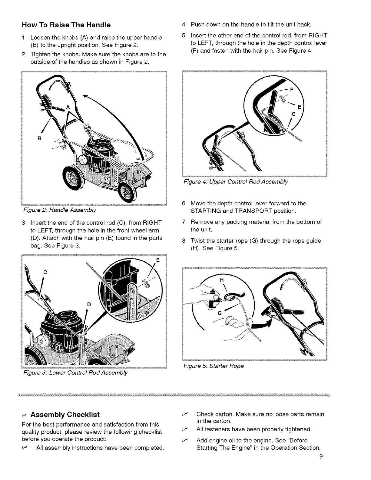
How To Raise The Handle
45Push down on the handle to tilt the unit back.
1 Loosen the knobs (A) and raise the upper handle
(B) to the upright position. See Figure 2.
2 Tighten the knobs. Make sure the knobs are to the
outside of the handles as shown in Figure 2.
Figure 2: Handle Assembly
Insert the end of the control rod (C), from RIGHT
to LEFT, through the hole in the front wheel arm
(D). Attach with the hair pin (E) found in the parts
bag. See Figure 3.
Insert the other end of the control rod, from RIGHT
to LEFT, through the hole in the depth control lever
(F) and fasten with the hair pin. See Figure 4.
Figure 4: Upper Control Rod Assembly
6
Move the depth control lever forward to the
STARTING and TRANSPORT position.
7
Remove any packing material from the bottom of
the unit.
8
Twist the starter rope (G) through the rope guide
(H). See Figure 5,
Figure 3: Lower Control Rod Assembly
_- Assembly Checklist _"
For the best performance and satisfaction from this
quality product, please review the following checklist _'
before you operate the product: _,
_' All assembly instructions have been completed.
Figure 5: Starter Rope
Check carton. Make sure no loose parts remain
in the carton.
All fasteners have been properly tightened.
Add engine oil to the engine. See "Before
Starting The Engine" in the Operation Section.
9
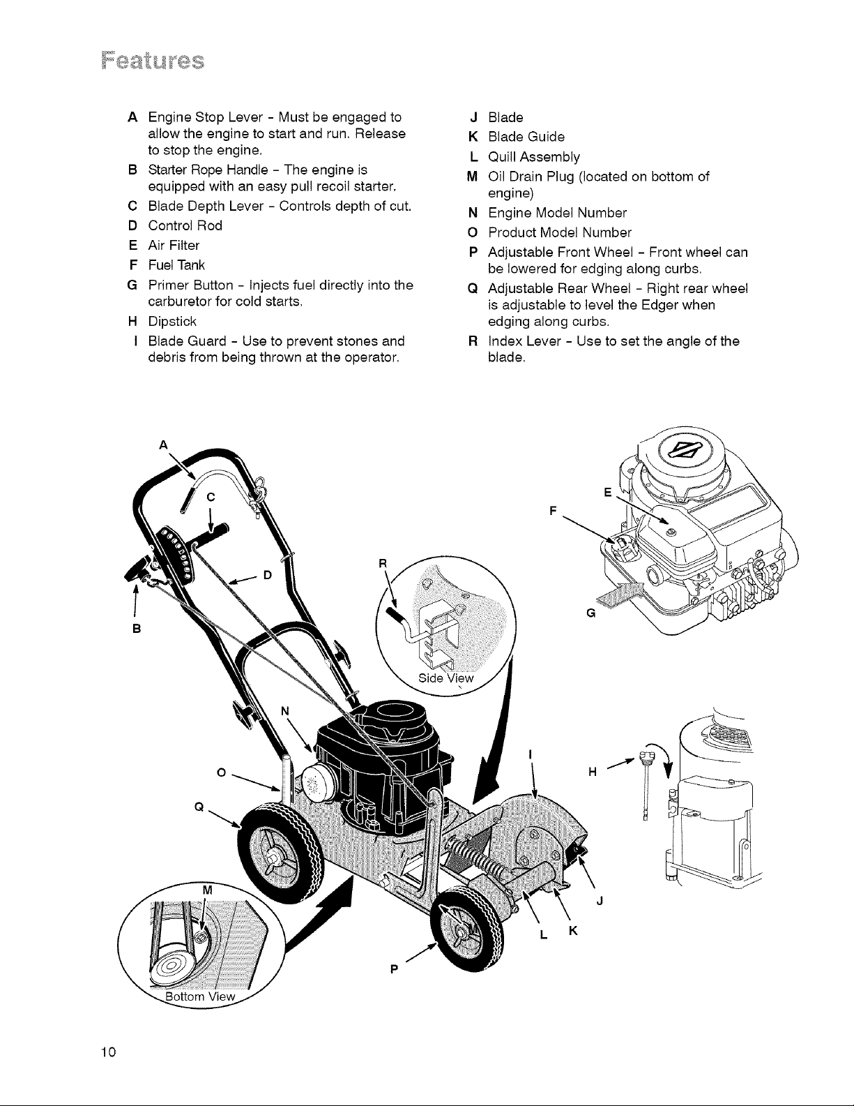
A EngineStopLever- Mustbeengagedto
allowtheenginetostartandrun,Release
tostoptheengine,
B StarterRopeHandle- Theengineis
equippedwithaneasypullrecoilstarter.
C BladeDepthLever- Controlsdepthofcut,
D ControlRod
E AirFilter
F FuelTank
G PrimerButton- Injectsfueldirectlyintothe
carburetorforcoldstarts,
H Dipstick
I BladeGuard- Usetopreventstonesand
debrisfrombeingthrownattheoperator,
A
\
J Blade
K BladeGuide
L QuillAssembly
IV1OilDrainPlug(locatedonbottomof
engine)
N EngineModelNumber
O ProductModelNumber
P AdjustableFrontWheel- Frontwheelcan
beloweredforedgingalongcurbs.
Q AdjustableRearWheel- Rightrearwheel
isadjustabletoleveltheEdgerwhen
edgingalongcurbs.
R IndexLever- Usetosettheangleofthe
blade,
R
Side View
10
Bottom View
Eye Protection
Read "Operator Safety Rules" section prior to using
this product.
Before Starting The Engine
CAUTION
This engine was shipped from the factory without
oil. If you start the engine without oil, the engine
will be damaged beyond repair and will not be
covered under warranty.
Oil Capacity
The engine holds approximately 20 ounces (0.6 liter)
of oil.
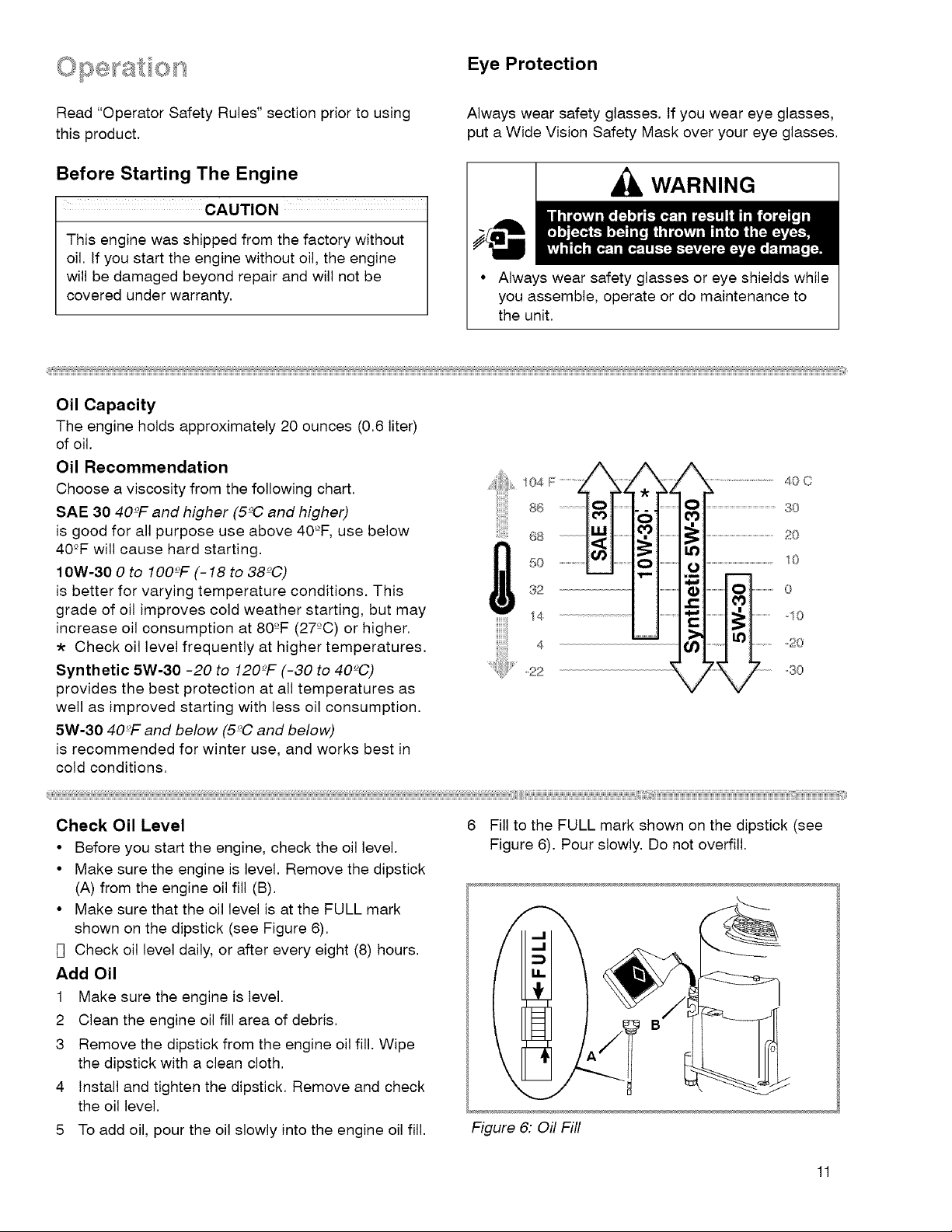
Oil Recommendation
Choose a viscosity from the following chart.
SAE 30 40°F and higher (5°0 and higher)
is good for all purpose use above 40°F, use below
40°F will cause hard starting.
10W-30 0 to IO0_F (- 18 to 38c'C)
is better for varying temperature conditions. This
grade of oil improves cold weather starting, but may
increase oil consumption at 80°F (27°C) or higher.
Check oil level frequently at higher temperatures.
Synthetic 5W-30 -20 to 120_'F (-30 to 40_C)
provides the best protection at all temperatures as
well as improved starting with less oil consumption.
5W-30 40_F and below (5°C and below)
is recommended for winter use, and works best in
cold conditions.
Always wear safety glasses. If you wear eye glasses,
put a Wide Vision Safety Mask over your eye glasses.
WARNING
• Always wear safety glasses or eye shields while
you assemble, operate or do maintenance to
the unit.
40 C
3O
20
I0
0
14
4
_,22
10
_20
-30
Check Oil Level
• Before you start the engine, check the oil level.
• Make sure the engine is level. Remove the dipstick
(A) from the engine oil fill (B).
• Make sure that the oil level is at the FULL mark
shown on the dipstick (see Figure 6).
F] Check oil level daily, or after every eight (8) hours.
Add Oil
1 Make sure the engine is level.
2 Clean the engine oil fill area of debris.
3 Remove the dipstick from the engine oil fill. Wipe
the dipstick with a clean cloth.
4 Install and tighten the dipstick. Remove and check
the oil level.
5 To add oil, pour the oil slowly into the engine oil fill.
6 Fill to the FULL mark shown on the dipstick (see
Figure 6). Pour slowly. Do not overfill.
Figure 6: Oil Fill
11
Gasoline Requirements
All gasoline is not the same. If a starting or
performance problem is encountered after new
gasoline has been used, try another service station or
change brands.
This engine is designed to operate on gasoline. The
emission control system for this engine is EM (Engine
Modifications).
Type of gasoline to use
Always use gasoline that meets these requirements:
• Clean, fresh, unleaded gasoline.
• A minimum of 87 octane/87 AKI (91 RON). At
altitudes over 5,000 feet, see "High-altitude use".
• Gasoline with up to 10% ethanol (gasohol) or up
to 15% MTBE (methyl tertiary butyl ether), is
acceptable.
• Use of any gasoline other than those approved
above will void the engine warranty. Some
areas require that fuel pumps be marked if the
gasoline contains alcohols or ethers. If you are not
sure if your gasoline contains alcohol or ethers that
are different than those approved above, then
check with the service station operator.
• Do not modify the engine fuel system or
carburetor to run on alternative fuels.
• Never mix oil with gasoline.
Gasoline Storage
Follow these guidelines when storing gasoline for
longer than 30 days:
• If fuel stabilizer is used, you do not need to drain
gasoline prior to storage.
• If no fuel stabilizer is used, then always remove
gasoline from engine during storage.
Fuel stabilizer
• If you do not want to remove the gasoline, add a
fuel stabilizer to any gasoline left in the fuel tank. A
fuel stabilizer will minimize gum deposits and acids.
If the fuel tank is almost empty, mix the fuel
stabilizer with fresh gasoline in a separate
container and add the mixture to the fuel tank.
Always follow the instructions on the stabilizer
container. Start the engine. Let the engine run for 3
minutes to allow the mixture to reach the
carburetor.
High-altitude use
At higher altitudes (over 5,000 feet), 85 octane / 85
AKI (89 RON) gasoline can be used. Operation at
high altitude may require a high-altitude carburetor jet
kit to improve performance and decrease fuel
consumption.
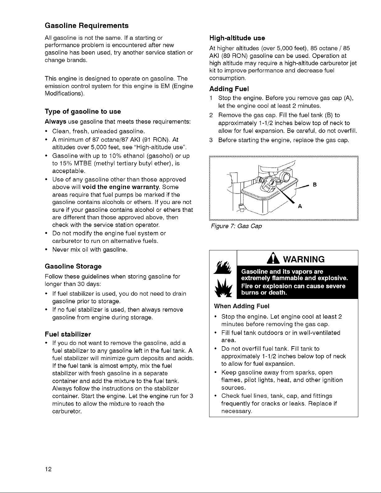
Adding Fuel
1 Stop the engine. Before you remove gas cap (A),
let the engine cool at least 2 minutes.
2 Remove the gas cap. Fill the fuel tank (B) to
approximately 1-1/2 inches below top of neck to
allow for fuel expansion. Be careful, do not overfill.
3 Before starting the engine, replace the gas cap.
Figure 7: Gas Cap
WARNING
When Adding Fuel
• Stop the engine. Let engine cool at least 2
minutes before removing the gas cap.
• Fill fuel tank outdoors or in well-ventilated
area.
• Do not overfill fuel tank. Fill tank to
approximately 1-1/2 inches below top of neck
to allow for fuel expansion.
• Keep gasoline away from sparks, open
flames, pilot lights, heat, and other ignition
sources.
• Check fuel lines, tank, cap, and fittings
frequently for cracks or leaks. Replace if
necessary.
12
How To Start The Engine
WARNING
• Start and run engine outdoors.
• Do not start or run engine in enclosed area,
even if doors or windows are open.
CAUTION
This engine was shipped from the factory without
oil. If you start the engine without oil, the engine
will be damaged beyond repair and will not be
covered under warranty.
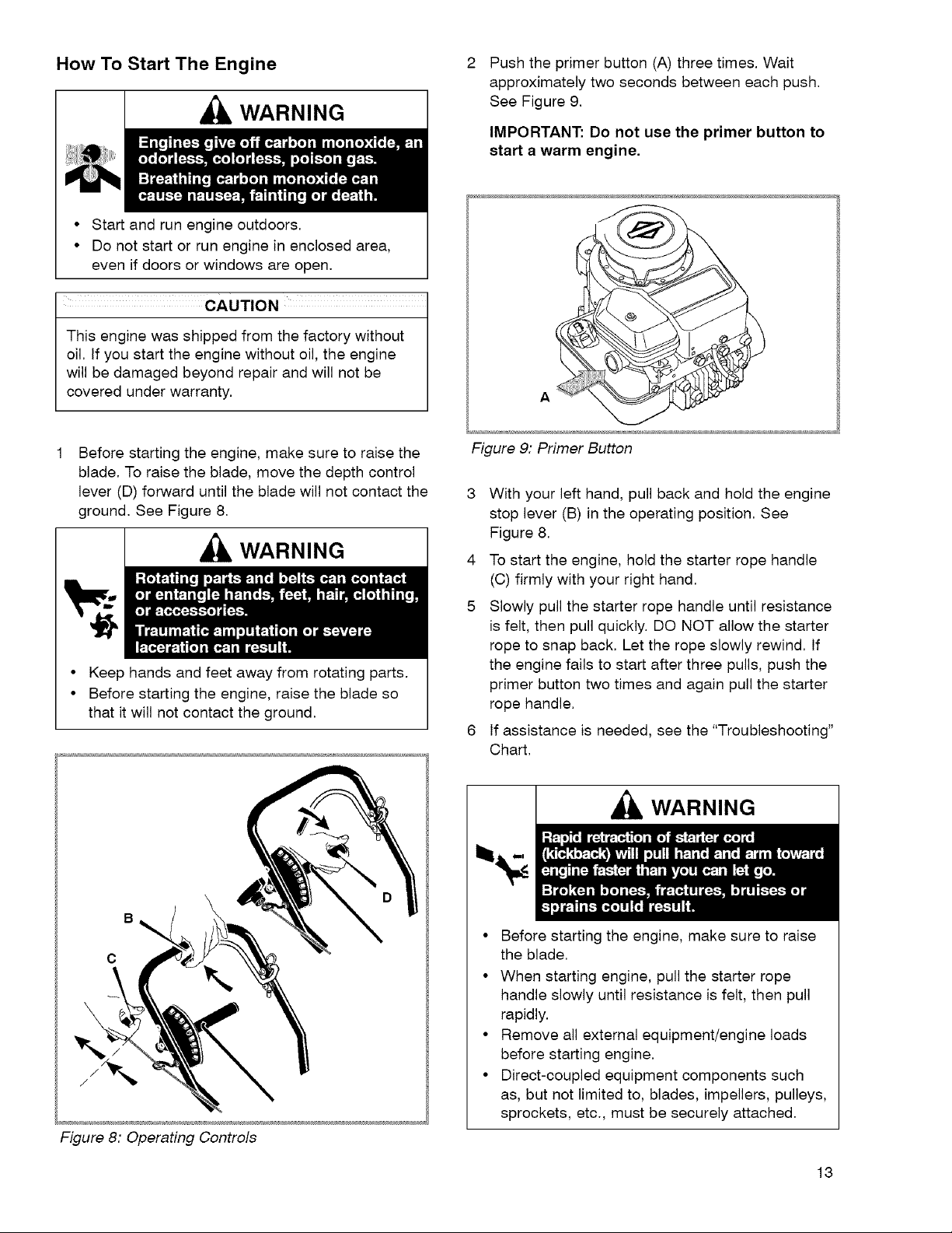
Push the primer button (A) three times. Wait
approximately two seconds between each push,
See Figure 9,
IMPORTANT: Do not use the primer button to
start a warm engine.
A
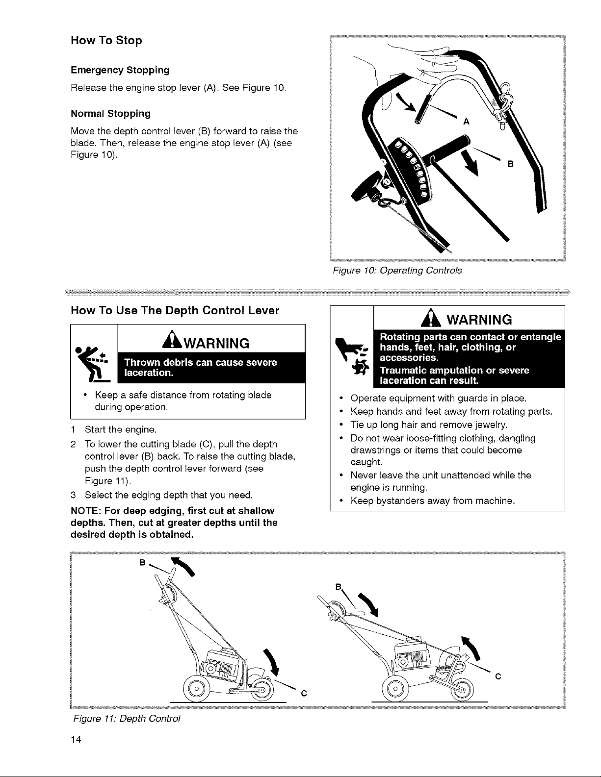
Before starting the engine, make sure to raise the
blade. To raise the blade, move the depth control
lever (D) forward until the blade will not contact the
ground. See Figure 8.
WARNING
• Keep hands and feet away from rotating parts.
• Before starting the engine, raise the blade so
that it will not contact the ground.
D
Figure 9: Primer Button
3 With your left hand, pull back and hold the engine
stop lever (B) in the operating position. See
Figure 8.
4 To start the engine, hold the starter rope handle
(C) firmly with your right hand.
5 Slowly pull the starter rope handle until resistance
is felt, then pull quickly. DO NOT allow the starter
rope to snap back. Let the rope slowly rewind. If
the engine fails to start after three pulls, push the
primer button two times and again pull the starter
rope handle.
6 If assistance is needed, see the "Troubleshooting"
Chart.
WARNING
o
Figure 8: Operating Controls
• Before starting the engine, make sure to raise
the blade.
• When starting engine, pull the starter rope
handle slowly until resistance is felt, then pull
rapidly.
• Remove all external equipment/engine loads
before starting engine.
• Direct-coupled equipment components such
as, but not limited to, blades, impellers, pulleys,
sprockets, etc., must be securely attached.
13
How To Stop
Emergency Stopping
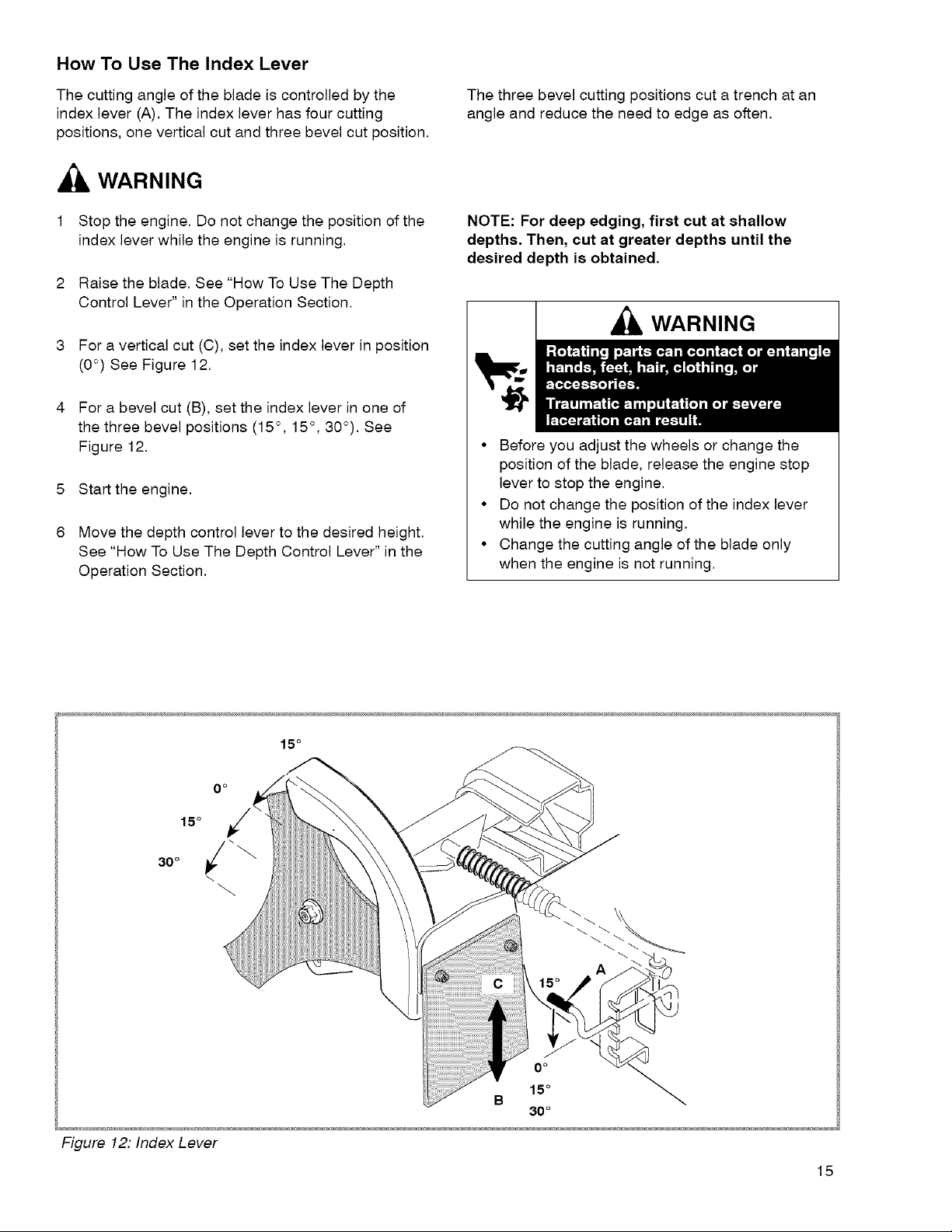
Release the engine stop lever (A). See Figure 10.
Normal Stopping
Move the depth control lever (B) forward to raise the
blade. Then, release the engine stop lever (A) (see
Figure 10).
Figure 10: Operating Controls
How To Use The Depth Control Lever
_,WARNING
• Keep a safe distance from rotating blade
during operation.
1 Start the engine.
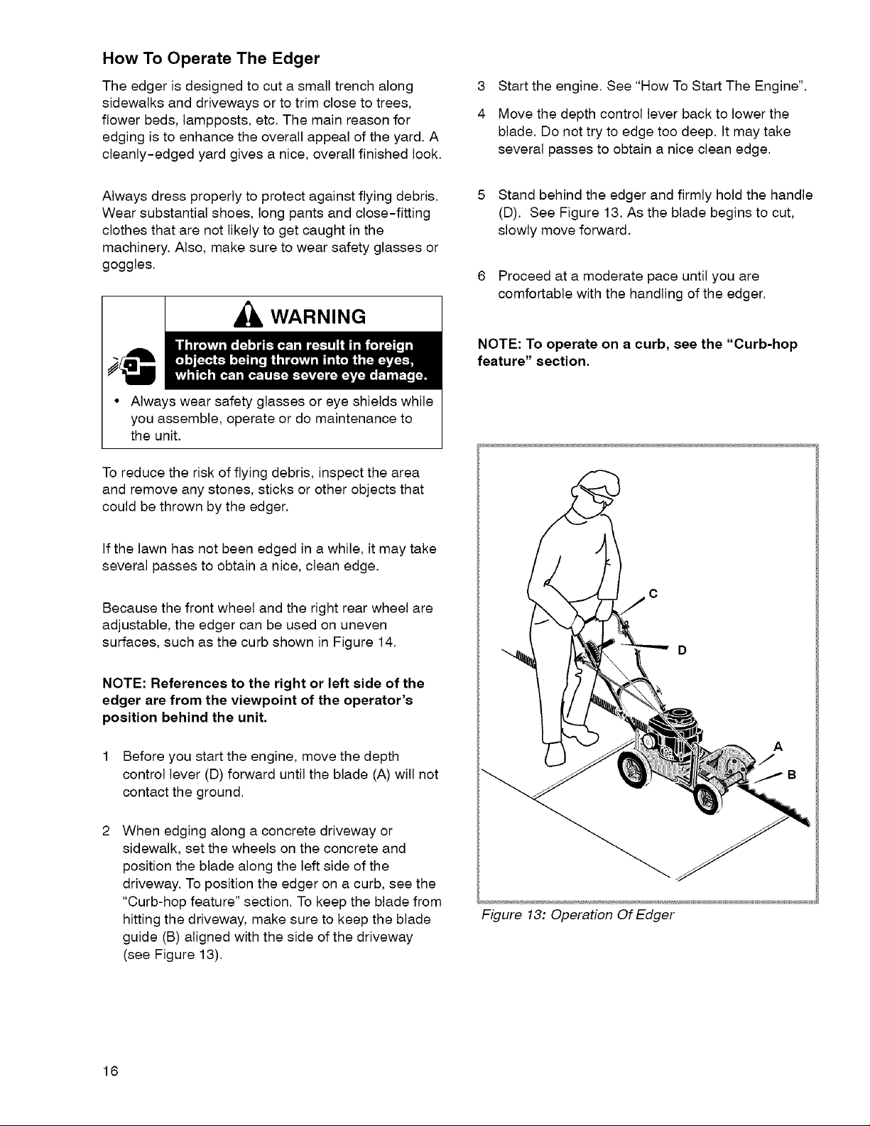
2 To lower the cutting blade (C), pull the depth
control lever (B) back. To raise the cutting blade,
push the depth control lever forward (see
Figure 11).
3 Select the edging depth that you need.
NOTE: For deep edging, first cut at shallow
depths. Then, cut at greater depths until the
desired depth is obtained.
B
WARNING
• Operate equipment with guards in place.
• Keep hands and feet away from rotating parts.
• Tie up long hair and remove jewelry.
• Do not wear loose-fitting clothing, dangling
drawstrings or items that could become
caught.
• Never leave the unit unattended while the
engine is running.
• Keep bystanders away from machine.
Figure 11:Depth Control
14
c
How To Use The Index Lever
The cutting angle of the blade is controlled by the
index lever (A). The index lever has four cutting
positions, one vertical cut and three bevel cut position.
WARNING
1 Stop the engine. Do not change the position of the
index lever while the engine is running.
2 Raise the blade. See "How To Use The Depth
Control Lever" in the Operation Section.
3 For a vertical cut (C), set the index lever in position
(0 °) See Figure 12.
4 For a bevel cut (B), set the index lever in one of
the three bevel positions (15 °, 15 °, 30°). See
Figure 12.
5 Start the engine.
6 Move the depth control lever to the desired height.
See "How To Use The Depth Control Lever" in the
Operation Section.
The three bevel cutting positions cut a trench at an
angle and reduce the need to edge as often.
NOTE: For deep edging, first cut at shallow
depths. Then, cut at greater depths until the
desired depth is obtained.
WARNING
• Before you adjust the wheels or change the
position of the blade, release the engine stop
lever to stop the engine.
• Do not change the position of the index lever
while the engine is running.
• Change the cutting angle of the blade only
when the engine is not running.
Figure 12: Index Lever
0 o
0 o
15 °
B
30 °
15
How To Operate The Edger
The edger is designed to cut a small trench along
sidewalks and driveways or to trim close to trees,
flower beds, lampposts, etc. The main reason for
edging is to enhance the overall appeal of the yard. A
cleanly-edged yard gives a nice, overall finished look.
3
Start the engine. See "How To Start The Engine".
4
Move the depth control lever back to lower the
blade. Do not try to edge too deep. It may take
several passes to obtain a nice clean edge.
Always dress properly to protect against flying debris.
Wear substantial shoes, long pants and close-fitting
clothes that are not likely to get caught in the
machinery. Also, make sure to wear safety glasses or
goggles.
WARNING
• Always wear safety glasses or eye shields while
you assemble, operate or do maintenance to
the unit.
To reduce the risk of flying debris, inspect the area
and remove any stones, sticks or other objects that
could be thrown by the edger.
If the lawn has not been edged in a while, it may take
several passes to obtain a nice, clean edge.
5 Stand behind the edger and firmly hold the handle
(D). See Figure 13. As the blade begins to cut,
slowly move forward.
6 Proceed at a moderate pace until you are
comfortable with the handling of the edger.
NOTE: To operate on a curb, see the "Curb-hop
feature" section.
Because the front wheel and the right rear wheel are
adjustable, the edger can be used on uneven
surfaces, such as the curb shown in Figure 14.
NOTE: References to the right or left side of the
edger are from the viewpoint of the operator's
position behind the unit.
1 Before you start the engine, move the depth
control lever (D) forward until the blade (A) will not
contact the ground.
When edging along a concrete driveway or
sidewalk, set the wheels on the concrete and
position the blade along the left side of the
driveway. To position the edger on a curb, see the
"Curb-hop feature" section. To keep the blade from
hitting the driveway, make sure to keep the blade
guide (B) aligned with the side of the driveway
(see Figure 13).
Figure 13: Operation Of Edger
16
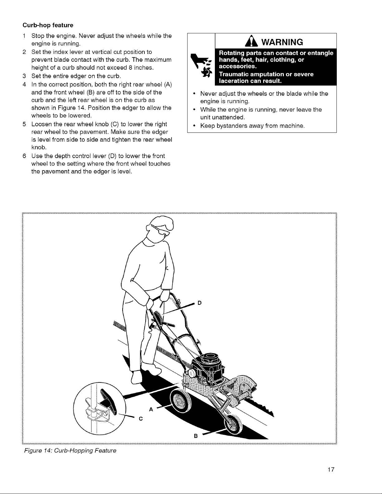
Curb-hopfeature
1 Stoptheengine.Neveradjustthewheelswhilethe
engineisrunning.
2 Settheindexleveratverticalcutpositionto
preventbladecontactwiththecurb.Themaximum
heightofacurbshouldnotexceed8 inches.
3 Settheentireedgeronthecurb.
4 Inthecorrectposition,boththerightrearwheel(A)
andthefrontwheel(B)areofftothesideofthe
curbandtheleftrearwheelisonthecurbas
showninFigure14.Positiontheedgertoallowthe
wheelstobelowered.
5 Loosentherearwheelknob(C)tolowertheright
rearwheeltothepavement.Makesuretheedger
islevelfromsidetosideandtightentherearwheel
knob.
6 Usethedepthcontrollever(D)tolowerthefront
wheeltothesettingwherethefrontwheeltouches
thepavementandtheedgerislevel.
WARNING
• Never adjust the wheels or the blade while the
engine is running.
• While the engine is running, never leave the
unit unattended.
• Keep bystanders away from machine.
Figure 14: Curb-Hopping Feature
A
C
B
17
Edging Tips
• Edging is best performed when conditions are dry.
If the soil is too wet, dirt becomes packed around
the blade causing premature belt wear and
decreased performance.
If dirt does become packed around the blade, stop
the engine and remove the wire from the spark
plug. Remove the packed dirt and debris from the
blade,
• For deep edging, first cut at shallow depths. Then,
cut at greater depths until the desired depth is
obtained.
• For uniform edging, make sure the blade guide
rides on the surface.
• Before you begin mowing, try first edging around
the lawn. Use the edger along hard edges such as
sidewalks and driveways.
WARNING
• Operate equipment with guards in place.
• Keep hands and feet away from rotating parts.
• Tie up long hair and remove jewelry.
• Do not wear loose-fitting clothing, dangling
drawstrings or items that could become
caught.
• Before unclogging the blade or making
repairs, stop the engine by releasing the
engine stop lever. Disconnect the wire from
the spark plug.
• Never leave the unit unattended while the
engine is running.
• Keep bystanders away from machine.
18
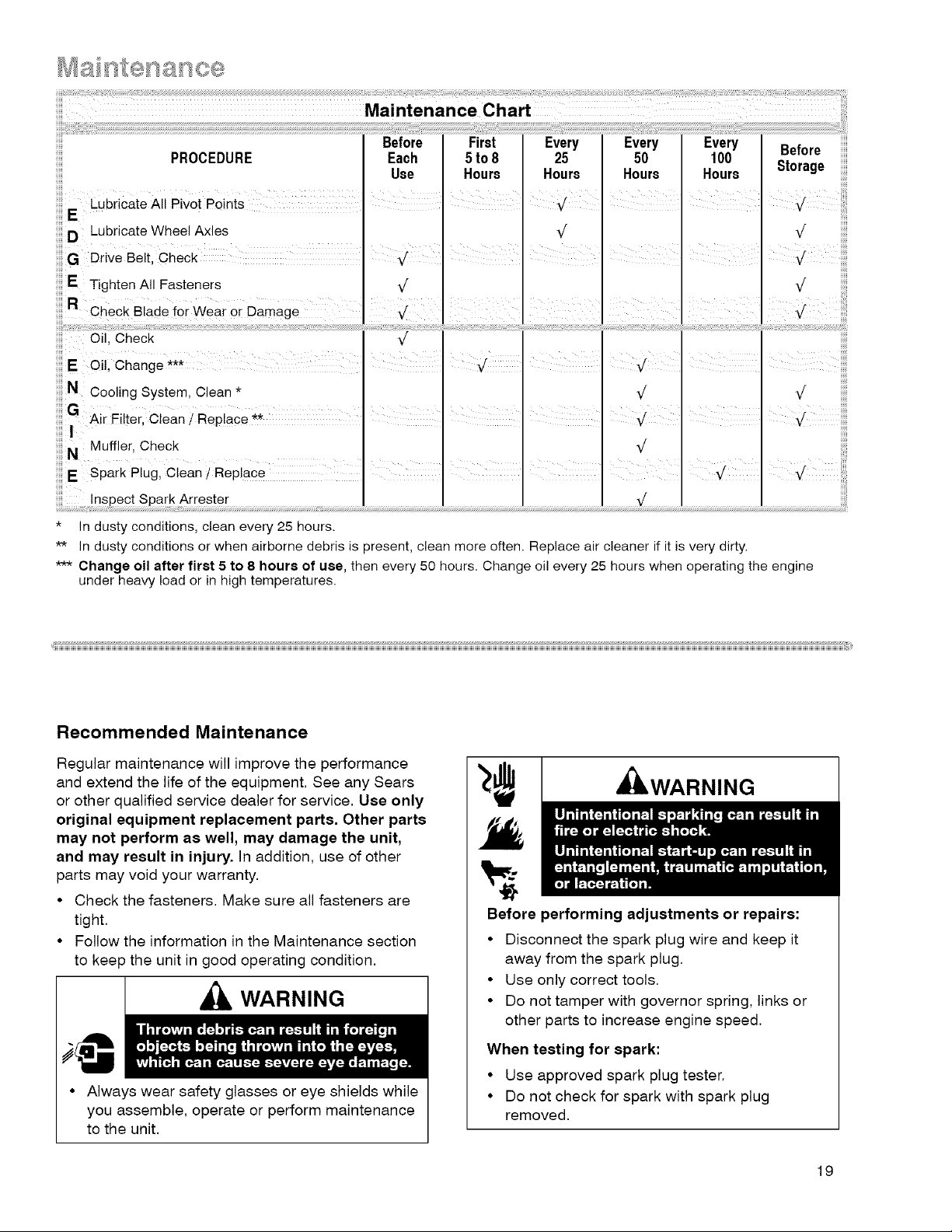
* In dusty conditions, clean every 25 hours.
** In dusty conditions or when airborne debris is present, clean more often. Replace air cleaner if it is very dirty.
*** Change oil after first 5 to 8 hours of use, then every 50 hours. Change oi! every 25 hours when operating the engine
under heavy load or in high temperatures.
Recommended Maintenance
Regular maintenance will improve the performance
and extend the life of the equipment. See any Sears
or other qualified service dealer for service. Use only
original equipment replacement parts, Other parts
may not perform as well, may damage the unit,
and may result in injury, In addition, use of other
parts may void your warranty.
• Check the fasteners. Make sure all fasteners are
tight.
• Follow the information in the Maintenance section
to keep the unit in good operating condition,
WARNING
Before performing adjustments or repairs:
• Disconnect the spark plug wire and keep it
away from the spark plug.
• Use only correct tools.
• Do not tamper with governor spring, links or
other parts to increase engine speed.
WARNING
• Always wear safety glasses or eye shields while
you assemble, operate or perform maintenance
to the unit.
When testing for spark:
• Use approved spark plug tester.
• Do not check for spark with spark plug
removed.
19
How To Remove The Belt
The belt is made of a special compound. If the belt
becomes worn or breaks, replace the belt with an
original equipment belt.
1 Disconnect the spark plug wire from the spark
plug.
2 Tilt the machine backwards on the handle. Secure
the top of the handle under a bench or against a
wall,
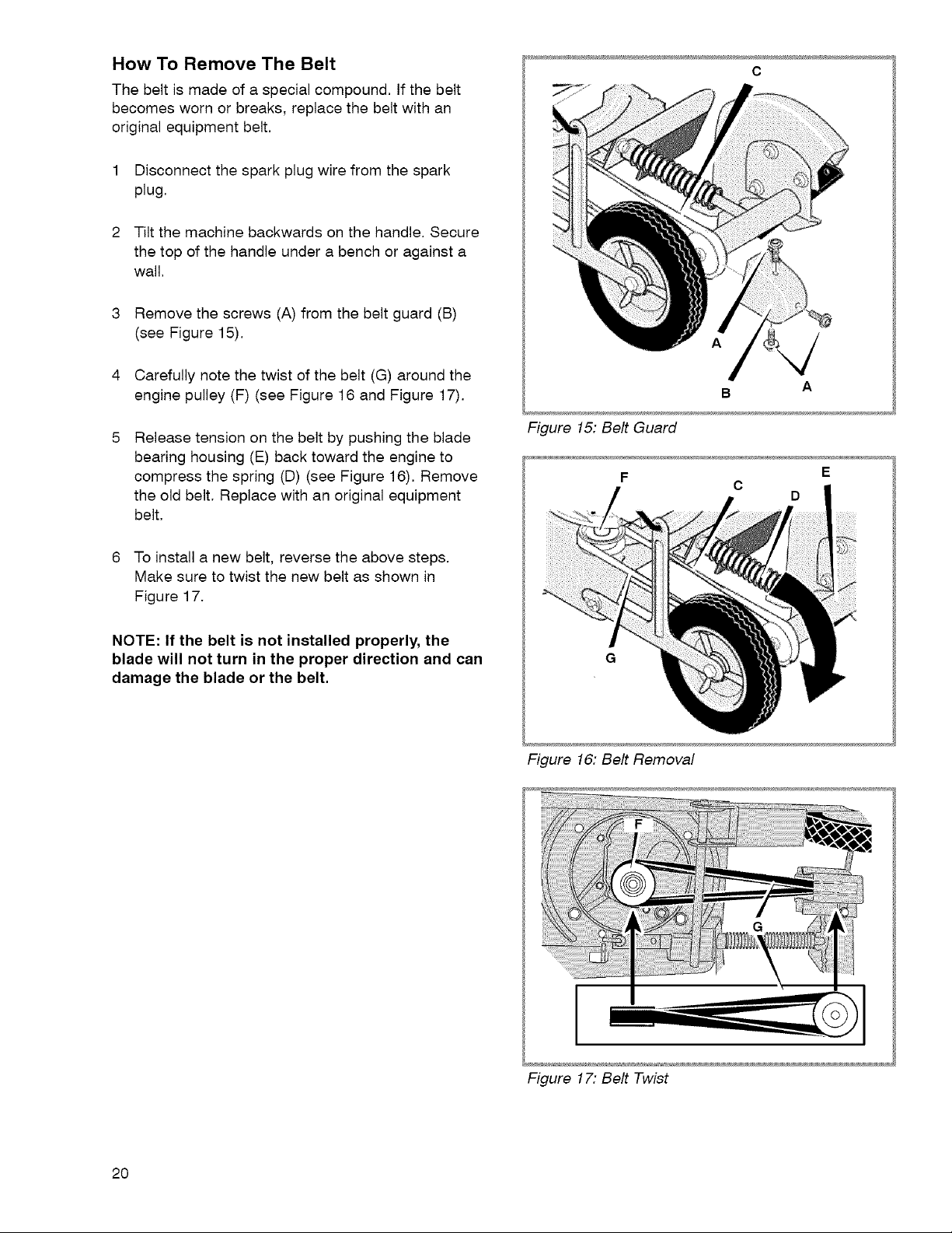
3 Remove the screws (A) from the belt guard (B)
(see Figure 15).
o
A
4 Carefully note the twist of the belt (G) around the
engine pulley (F) (see Figure 16 and Figure 17).
Release tension on the belt by pushing the blade
bearing housing (E) back toward the engine to
compress the spring (D) (see Figure 16). Remove
the old belt. Replace with an original equipment
belt.
6 To install a new belt, reverse the above steps.
Make sure to twist the new belt as shown in
Figure 17.
NOTE: If the belt is not installed properly, the
blade will not turn in the proper direction and can
damage the blade or the belt.
Figure 15: Belt Guard
F E
Figure 16: Belt Removal
B A
C
D
2O
Figure 17: Belt Twist
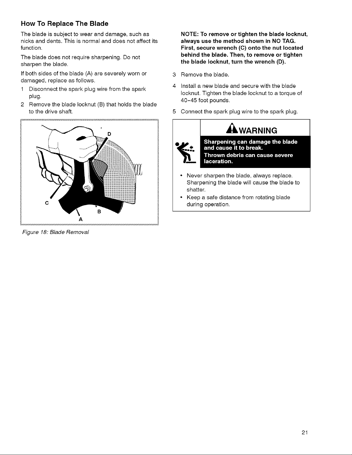
How To Replace The Blade
The blade is subject to wear and damage, such as
nicks and dents, This is normal and does not affect its
function.
The blade does not require sharpening, Do not
sharpen the blade.
If both sides of the blade (A) are severely worn or
damaged, replace as follows.
1 Disconnect the spark plug wire from the spark
plug.
2 Remove the blade Iocknut (B) that holds the blade
to the drive shaft.
c
B
A
NOTE: To remove or tighten the blade Iocknut,
always use the method shown in NO TAG.
First, secure wrench (C) onto the nut located
behind the blade. Then, to remove or tighten
the blade Iocknut, turn the wrench (D).
3
Remove the blade.
4
Install a new blade and secure with the blade
Iocknut. Tighten the blade Iocknut to a torque of
40-45 foot pounds.
Connect the spark plug wire to the spark plug.
IbWARNING
• Never sharpen the blade, always replace.
Sharpening the blade will cause the blade to
shatter,
• Keep a safe distance from rotating blade
during operation,
Figure 18: Blade Removal
21
Engine Maintenance
CAUTION
All the components used to build this engine must
remain in place for the proper operation of this
engine.
Emission Control
Maintenance, replacement or repair of the emission
control devices and systems may be performed by
any non-road engine repair establishment or
individual. However, to obtain no charge repairs under
the terms and provisions of the Sears warranty
statement, any service or emission control part repair
or replacement must be performed by a factory
authorized dealer. See the Emission Warranty.
Carburetor Adjustment
Never make unnecessary adjustments to the
carburetor. The carburetor was set at the factory to
operate efficiently under most applications. However,
if adjustments are required, see any Sears or other
qualified service dealer for service.
CAUTION
The manufacturer of the equipment on which this
engine is installed specifies top speed at which the
engine will be operated. DO NOT EXCEED this
speed.
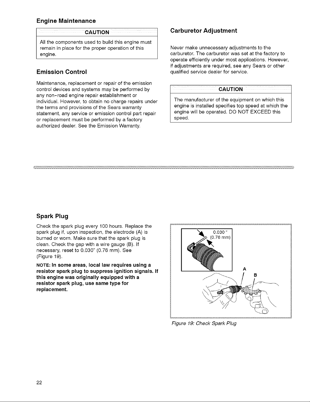
Spark Plug
Check the spark plug every 100 hours. Replace the
spark plug if, upon inspection, the electrode (A) is
burned or worn. Make sure that the spark plug is
clean. Check the gap with a wire gauge (B). If
necessary, reset to 0.030" (0.76 mm). See
(Figure 19).
NOTE: In some areas, local law requires using a
resistor spark plug to suppress ignition signals. If
this engine was originally equipped with a
resistor spark plug, use same type for
replacement.
A
B
Figure 19: Check Spark Plug
22
 Loading...