

Craftsman 536772341 Owner’s Manual
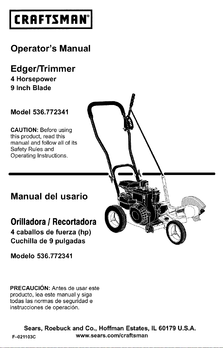
I(RRFTSMRN1
Operator's Manual
Edger/Trimmer
4 Horsepower
9 Inch Blade
Model 536.772341
CAUTION: Before using
this product, read this
manual and follow all of its
Safety Rules and
Operating Instructions.
Manual del usario
0rilladora/ Recortadora
4 caballos de fuerza (hp)
Cuchilla de 9 pulgadas
Modelo 536.772341
PRECAUCION: Antes de usar este
producto, lea este manual y siga
todas las normas de seguridad e
instruccionesde operaci6n.
Sears, Roebuck and Co., Hoffman Estates, IL 60179 U.S.A.
F_)21103C www.sears.com/craftsman
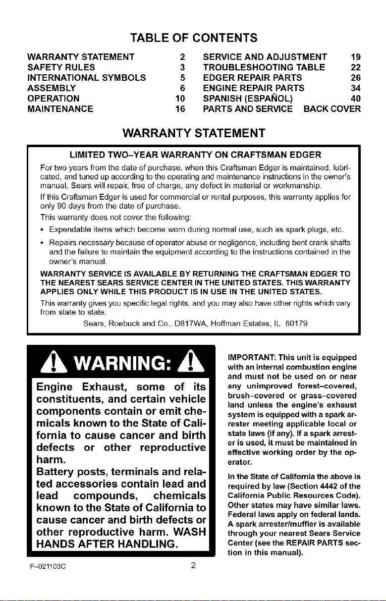
TABLE OF CONTENTS
WARRANTY STATEMENT
SAFETY RULES
INTERNATIONAL SYMBOLS
ASSEMBLY
OPERATION
MAINTENANCE
2 SERVICE AND ADJUSTMENT 19
3 TROUBLESHOOTING TABLE 22
5 EDGER REPAIR PARTS 26
6 ENGINE REPAIR PARTS 34
10 SPANISH (ESPAI_IOL) 40
16 PARTS AND SERVICE BACK COVER
WARRANTY STATEMENT
LIMITED TWO-YEAR WARRANTY ON CRAFTSMAN EDGER
For two years from the date of purchase, when this Craftsman Edger is maintained, lubri-
cated, and tuned up according to the operating and maintenance instructions in the owner's
manual, Sears will repair, free of charge, any defect in material or workmanship.
If this Craftsman Edger is used for commercial or rental purposes, this warranty applies for
only 90 days from the date of purchase.
This warranty does not cover the following:
• Expendable items which become worn during normal use, such as spark plugs, etc.
• Repairs necessary because of operator abuse or negiigence, including bent crank shafts
and the failure to maintain the equipment according to the instructions contained in the
owner's manual.
WARRANTY SERVICE IS AVAILABLE BY RETURNING THE CRAFTSMAN EDGER TO
THE NEAREST SEARS SERVICE CENTER IN THE UNITED STATES. THIS WARRANTY
APPLIES ONLY WHILE THIS PRODUCT IS IN USE IN THE UNITED STATES.
This warranty gives you specific Iegal rights, and you may also have other rights which vary
from state to state.
Sears, Roebuck and Co., D817WA, Hoffman Estates, IL 60179
Engine Exhaust, some of its
constituents, and certain vehicle
components contain or emit che-
micals known to the State of Cali-
fornia to cause cancer and birth
defects or other reproductive
harm.
Battery posts, terminals and rela-
ted accessories contain lead and
lead compounds, chemicals
known to the State of California to
cause cancer and birth defects or
other reproductive harm. WASH
HANDS AFTER HANDLING.
F_021103C
IMPORTANT: This unit is equipped
with an internal combustion engine
and must not be used on or near
any unimproved forest-covered,
brush-covered or grass-covered
land unless the engine's exhaust
system is equipped with a spark at-
rester meeting applicable local or
state laws (if any). If a spark arrest-
er is used, it must be maintained in
effective working order by the op-
erator.
In the State of California the above is
required by law (Section 4442 of the
California Public Resources Code),
Other states may have similar laws,
Federal laws apply on federal lands,
A spark attester/muffler is available
through your nearest Sears Service
Center (see the REPAIR PARTS sec-
tion in this manual),

SAFETY RULES
Safe Operation Practices for Edger.
WARNING: Look for this symbol to point out important safety precautions.
It means: "Attention! Become Alert! Your Safety Is Involved."
_IL ARNING: To prevent acciden-
ing repairs, always disconnect spark
plug wire and put wire where it cannot
contact the spark plug.
Before Use
• Read the owner's manual carefutty. Be
• Do not operate the Edger without weadng
• Keep the area of operation clear of all per-
• Thoroughly inspect the area where the
Fuel Safety
• Handle fuel with care; it is highly flam-
• Use an approved container.
• Check fuel supply before each use, allow-
• Fill fueI tank outdoors with extreme care.
• Never remove the fuel tank cap or add fuel
• Never store fuel or Edger with fuel in the
F_)211030
tal starting when setting-up,
transporting, adjusting or mak-
thoroughly familiar with the controls and
the proper use of the Edger. Know how to
stop the Edger and disengage the controls
quickly.
adequate outer garments. Wear footwear
that will improve footing on slippery sur-
faces.
sons, particularly small children and pets.
Edger is to be used and remove all foreign
objects.
mable.
ing space for expansion as the heat of the
engine and/or sun can cause fuel to ex-
pand.
Never fill fuel tank indoors. Replace fuel
tank cap securely and wipe up spilled fuel.
to a running or hot engine.
tank inside a building where fumes may
reach an open flame.
Operating Safety
• Never allow children or young teenagers to
operate the Edger. Keep them away while
it is operating. Never allow adults to oper-
ate the Edger without proper instruction.
• Do not operate this machine if you are tak-
ing drugs or other medication which can
cause drowsiness or affect your ability to
operate this machine.
• Do not use this machine if you are mentaliy
or physically unable to operate this ma-
chine safely.
• Always wear safety glasses or eye shields
during operation or whiIe performing an
adjustment or repair to protect your eyes
from foreign objects that may be thrown
from the Edger.
• Do not put hands or feet near or under ro-
tating parts.
• Exercise extreme caution when operating
on or crossing gravel drives, walks, or
roads. Stay alert for hidden hazards or
traffic.
• Exeroise caution to avoid slipping or falling.
• Never operate the Edger without proper
guards, plates, or other safety protective
devices in place.
• Never operate the Edger at high transport
speeds on slippery surfaces. Look behind
and use care when backing.
• Never allow bystanders near the Edger.
• Keep children and pets away while
operating.
• Never operate the Edger without good visi-
bility or light.
• Do not run the engine indoors. The ex-
haust fumes are dangerous, containing
CARBON MONOXIDE, an ODGRLESS
and DEADLY GAS.
• Take all possible precautions when leaving
the Edger unattended. Stop the engine.
• DO not ovedoad the Edger capacity by at-
tempting to till too deep at too fast a rate.
3
SAFETY RULES
Safe Storage
• Always refer to the owner's manual instruc-
tions for important details if the Edger is to
be stored for an extended period.
• Never store the Edger with fuel in the fuel
tank inside a building where ignition
sources are present such as water and
space heaters, clothes dryers, and the like.
Allow the engine to cool before storing in
any enclosure.
• Keep the Edger in safe working condition.
Check all fasteners at frequent intervals for
proper tightness.
Repair / Adjustments Safety
• After striking a foreign object, stop the en-
gine. Remove the wire from the spark plug,
and keep the wire away from the plug to
prevent accidental starting. Thoroughly in-
spect the Edger for any damage, and re-
pair the damage before restarting and
operating it.
If Edger should start to vibrate abnormally,
stop engine and check immediately for the
cause. Vibration is generally a warning of
trouble.
Stop the engine whenever you leave the
operating position. Also, disconnect the
spark plug wire before unclogging the
blade and when making any repairs, ad-
justments, or inspections.
When cleaning, repairing, or inspecting,
shut off the engine and make certain all
moving parts have stopped.
Never attempt to make any adjustments
while the engine is running.
F=021103C 4

SAFETY RULES
INTERNATIONAL SYMBOLS
IMPORTANT: Many of the following symbols are located on your unit or on literature sup-
plied with the product. Before you operate the unit, learn and understand the purpose for
each symbol.
Control And Operating Symbols
Slow Fast Fuel Oil
Primer Button
Safety WarningSymbols
A
WARNING WARNING
Thrown Objects. Rotating Parts. Stop Engine. WARNING
Keep Bystanders Away. Disconnect Spark Wire Before
IMPORTANT WARNING STOP
Read Owner's Manual Wear Eye Protection
Before Operating
This Machine.
F_021103C 5
Making Adjustments.
ASSEMBLY
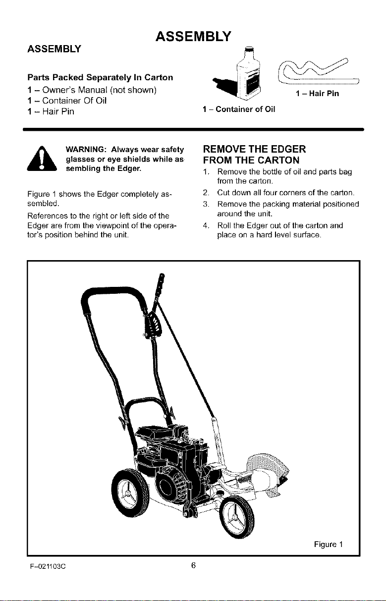
ASSEMBLY
Parts Packed Separately In Carton
1- Owner's Manual (not shown)
1- Container Of Oil
1- Hair Pin
glasses or eye shields while as,
WARNING: Always wear safety
sembling the Edger.
Figure 1 shows the Edgercompletely as-
sembled.
References to the right or left side of the
Edger are from the viewpoint of the opera-
tot's position behind the unit.
1 -HairPin
1 - Container of Oil
REMOVE THE EDGER
FROM THE CARTON
1. Remove the bottle of oil and parts bag
from the carton.
2. Cut down all four corners of the carton.
3. Remove the packing material positioned
around the unit.
4. Roll the Edger out of the carton and
place on a hard level surface.
F_021103C 6
Figure 1
ASSEMBLY
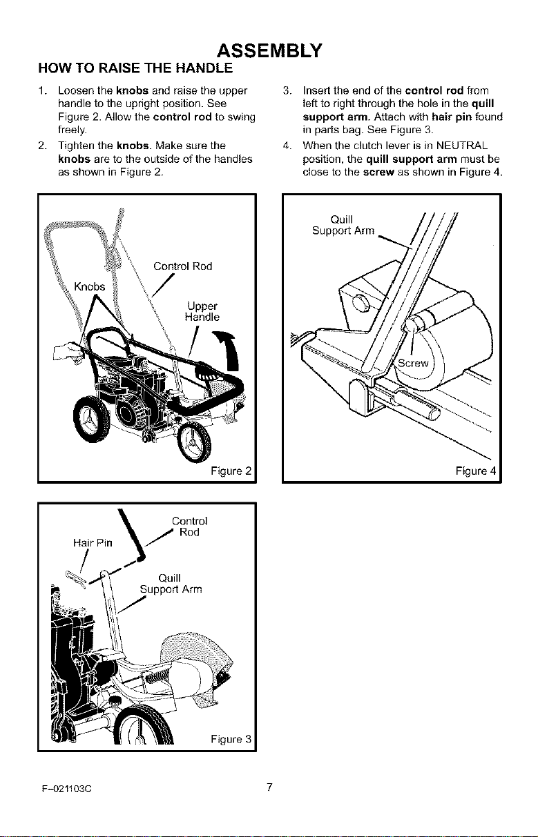
HOW TO RAISE THE HANDLE
1. Loosen the knobs and raise the upper
handle to the upright position. See
Figure 2. Allow the control rod to swing
freely.
2. Tighten the knobs. Make sure the
knobs are to the outside of the handles
as shown in Figure 2.
Control Rod
Upper
Handle
3. Insert the end of the control rod from
left to right through the hole in the quill
support arm. Attach with hair pin found
in parts bag. See Figure 3.
4. When the clutch lever is in NEUTRAL
position, the quill support arm must be
close to the screw as shown in Figure 4.
Quill
Support Arm
Figure 2
Hair Pin
F_021103C 7
Rod
Quill
upport Arm
Figure 3
Figure 4
ASSEMBLY
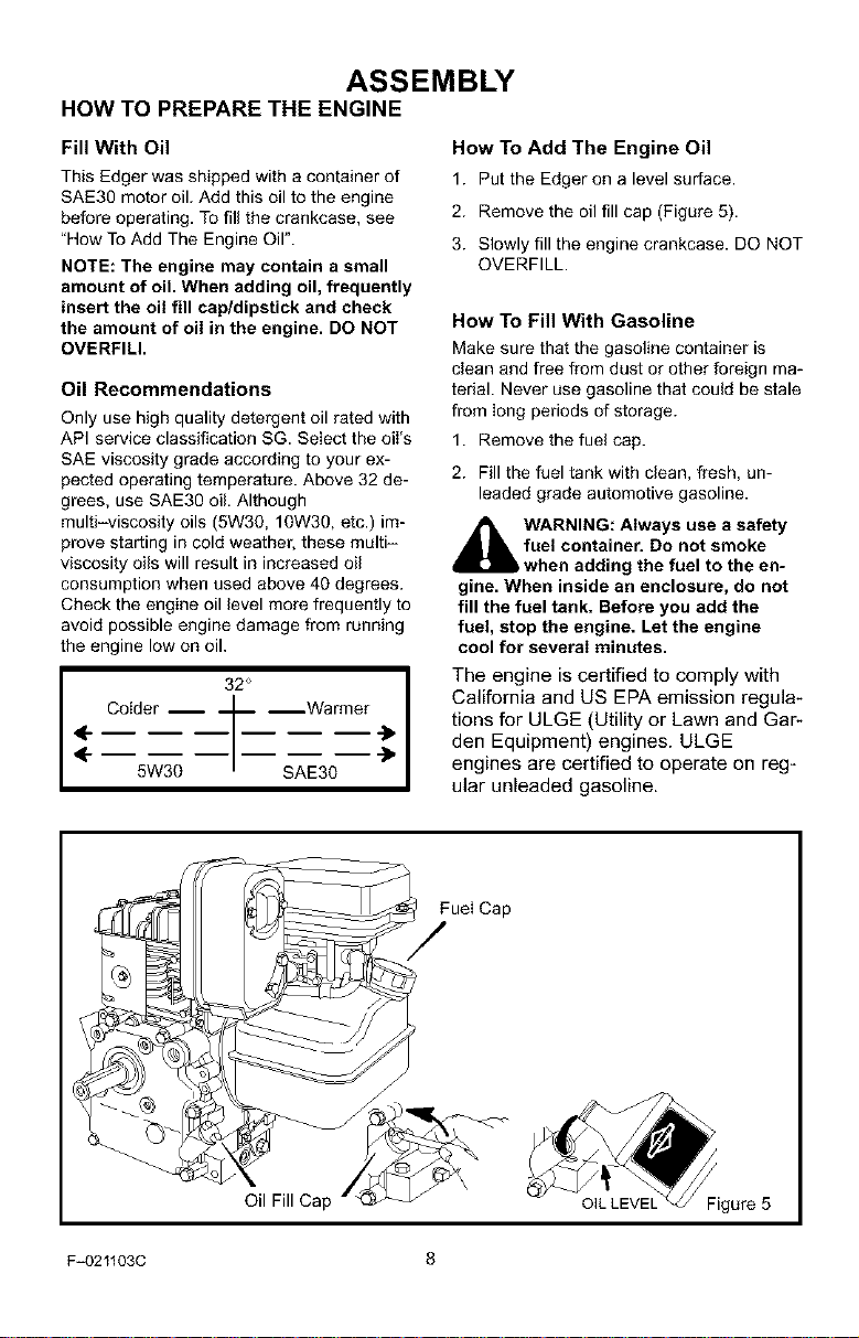
HOW TO PREPARE THE ENGINE
Fill With Oil
This Edger was shipped with a container of
SAE30 motor oil. Add this oil to the engine
before operating. To fill the crankcase, see
"How To Add The Engine Oil".
NOTE: The engine may contain a small
amount of oil. When adding oil, frequently
insert the oil fill cap/dipstick and check
the amount of oil in the engine. DO NOT
OVERFILl.
Oil Recommendations
Only use high quality detergent oil rated with
API service classification SG. Select the oil's
SAE viscosity grade according to your ex-
pected operating temperature. Above 32 de-
grees, use SAE30 oil. Although
multi-viscosity oils (5W30, lOW30, etc.) im-
prove starting in cold weather, these multi-
viscosity oils will result in increased oil
consumption when used above 40 degrees.
Check the engine oil level more frequently to
avoid possible engine damage from running
the engine low on oil.
32 °
4
Colder _ --Warmer
5W30 SAE30
_1 The engine is certified to comply with
How To Add The Engine Oil
1. Put the Edger on a level surface.
2. Remove the oil fill cap (Figure 5).
3. Slowly fill the engine crankcase. DO NOT
OVERFILL.
How To Fill With Gasoline
Make sure that the gasoline container is
clean and free from dust or other foreign ma-
terial. Never use gasoline that could be stale
from long periods of storage.
1. Remove the fuel cap.
2. Fill the fuel tank with clean, fresh, un-
leaded grade automotive gasoline.
_hlL ARNING: Always use a safety
fuel container. Do not smoke
when adding the fuel to the en=
gine. When inside an enclosure, do not
fill the fuel tank. Before you add the
fuel, stop the engine. Let the engine
cool for several minutes.
California and US EPA emission regula-
tions for ULGE (Utility or Lawn and Gar-
den Equipment) engines. ULGE
engines are certified to operate on reg-
ular unleaded gasoline.
Oil Fill Cap
F_021103C 8
Fuel Cap
ASSEMBLY
_" CHECKLIST
For the best performance and satisfaction
from this quality product, please review the
following checklist before you operate the
Edger:
#-" All assembly instructions have been
completed.
Check carton. Make sure no loose
parts remain in the carton.
All fasteners have been propedy tight-
ened.
As you learn how to use the Edger, pay extra
attention to the following important items:
#-'_" Engine oil is at proper level.
#-'_" Fuel tank is filled with a fresh, clean,
regular Unleaded gasoline.
#-'_" Become familiar and understand the
function of all controls. Before you
start the engine, operate all controls.
F_021103C 9
OPERATION
KNOW YOUR EDGER
READ THE OWNER'S MANUAL AND ALL SAFETY RULES BEFORE YOU OPERATE the
Edger. To familiarize yourself with the location of the controls, compare the illustrations with
your Edger. Save this manual for future reference.
ENGINE
Clutch Lever
Control Rod
Blade Guard
Starter
Handle "
Adjustable Rear Wheel
Curb Height Lever Front Wheel
Throttle Control (if equipped)- Con-
trols the engine speed.
Clutch Lever - Use to start and stop the
blade and control the depth of cut.
Adjustable Rear Wheel - Right rear
wheel is adjustable to level the Edger when
edging along a curb (curb-hopping).
Adjustable Front Wheel - Front wheel
is adjustable from side-to-side for balance.
The front wheel can also be adjusted down
for curb-hopping.
I_ Throttle
VIEW OF BLADE AREA
Index Lever
Blade
Recoil Starter Handle - The engine is
equipped with an easy pull recoil starter'.
Blade Guard - Use to prevent stones or
other material from being thrown at the oper-
ator.
Index Lever- Use the index lever to
change the angle of the blade. For edging,
set the blade in a vertical position. For trim-
ming, set the blade in a horizontal position.
Curb Height Lever- Use to set the
front wheel height on uneven surfaces.
Figure 6
EYE PROTECTION
Always wear safety glasses. If you wear eye
glasses, put a Wide Vision Safety Mask over
your eye glasses.
F_021103C
the Edger can result in foreign
WARNING: Debris thrown from
eyes, which can cause severe eye dam-
age. Always wear safety glasses or eye
shields when operating the Edger.
10
objects being thrown into the
OPERATION
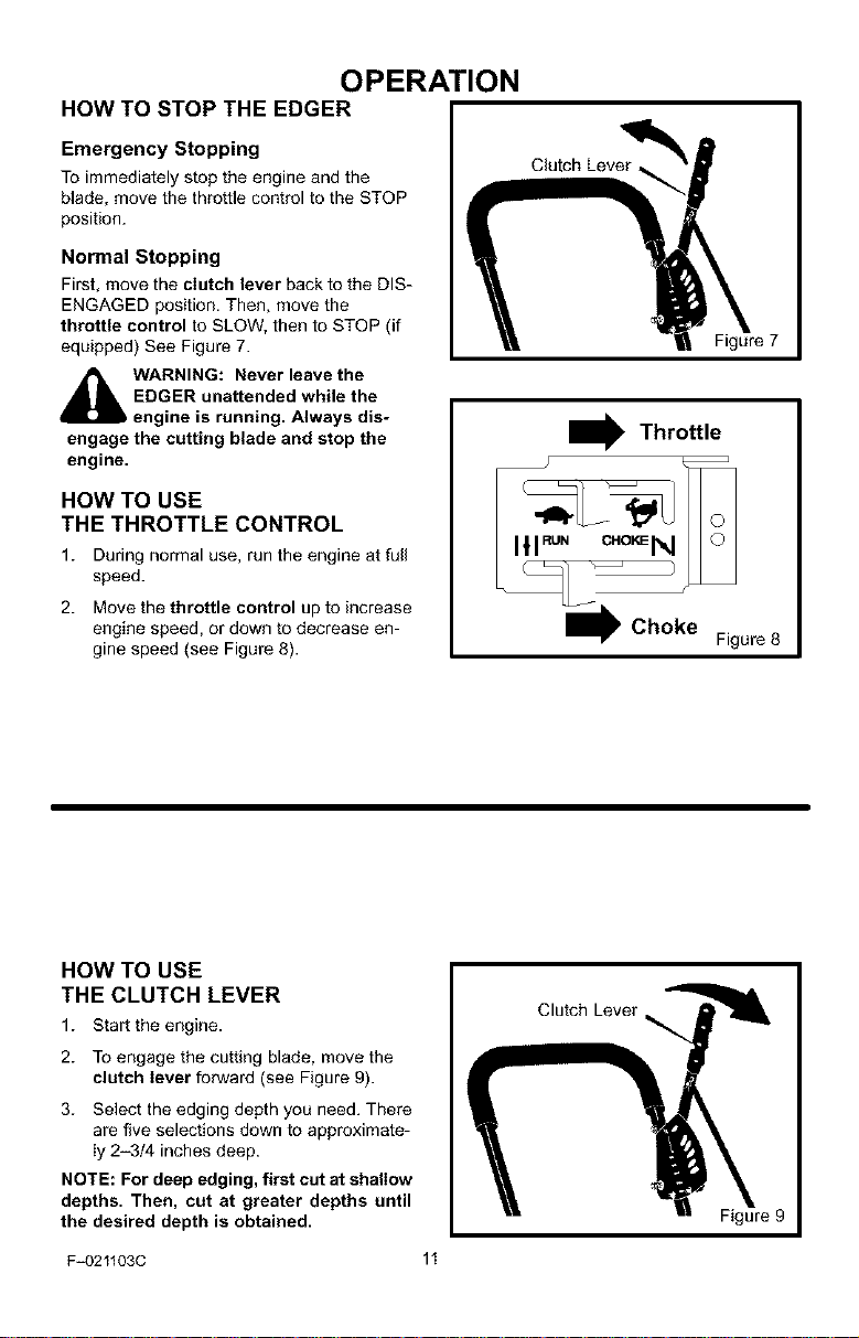
HOW TO STOP THE EDGER
Emergency Stopping
To immediately stop the engine and the
blade, move the throttle control to the STOP
position.
Normal Stopping
First, move the clutch lever back to the DIS-
ENGAGED position. Then, move the
throttle control to SLOW, then to STOP (if
equipped) See Figure 7.
Figure 7
_ ARNING: Never leave the
EDGER unattended while the
engine is running. Always dis-
engage the cutting blade and stop the
engine.
HOW TO USE
THE THROTTLE CONTROL
1. During normal use, run the engine at full
speed.
2. Move the throttle control up to increase
engine speed, or down to decrease en-
gine speed (see Figure 8).
HOW TO USE
THE CLUTCH LEVER
1. Star the engine.
2. To engage the cutting blade, move the
clutch lever forward (see Figure 9).
3. Select the edging depth you need. There
are five selections down to approximate-
ly 2-3/4 inches deep.
NOTE: For deep edging, first cut at shallow
depths. Then, cut at greater depths until
the desired depth is obtained.
F_021103C 11
I Throttle
Figure 8
Clutch Lever
Figure 9
OPERATION
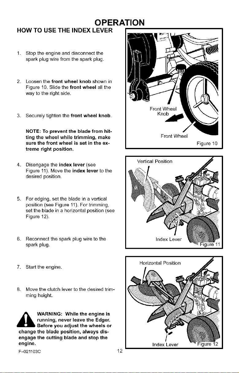
HOW TO USE THE INDEX LEVER
1. Stop the engine and disconnect the
spark plug wire from the spark plug.
2. Loosen the front wheel knob shown in
Figure 10. Slide the front wheel all the
way to the right side.
3. Securely tighten the front wheel knob.
Front Wheel
Knob
NOTE: To prevent the blade from hit-
ting the wheel while trimming, make
sure the front wheel is set in the ex-
treme right position.
4. Disengage the index lever (see
Figure 11). Move the index lever to the
desired position.
5. For edging, set the blade in a vertical
position (see Figure 11). For trimming,
set the blade in a horizontal position (see
Figure 12).
6. Reconnect the spark plug wire to the
spark plug.
7. Start the engine.
8. Move the clutch lever to the desired trim-
ming height.
Front Wheel
Figure 10
Vertical Position
Index Lever
Horizontal Position
_k WARNING: While the engine is
running, never leave the Edger.
Before you adjust the wheels or
change the blade position, always dis-
engage the cutting blade and stop the
engine.
F_021103C
Index Lever
12
Figure 12
OPERATION
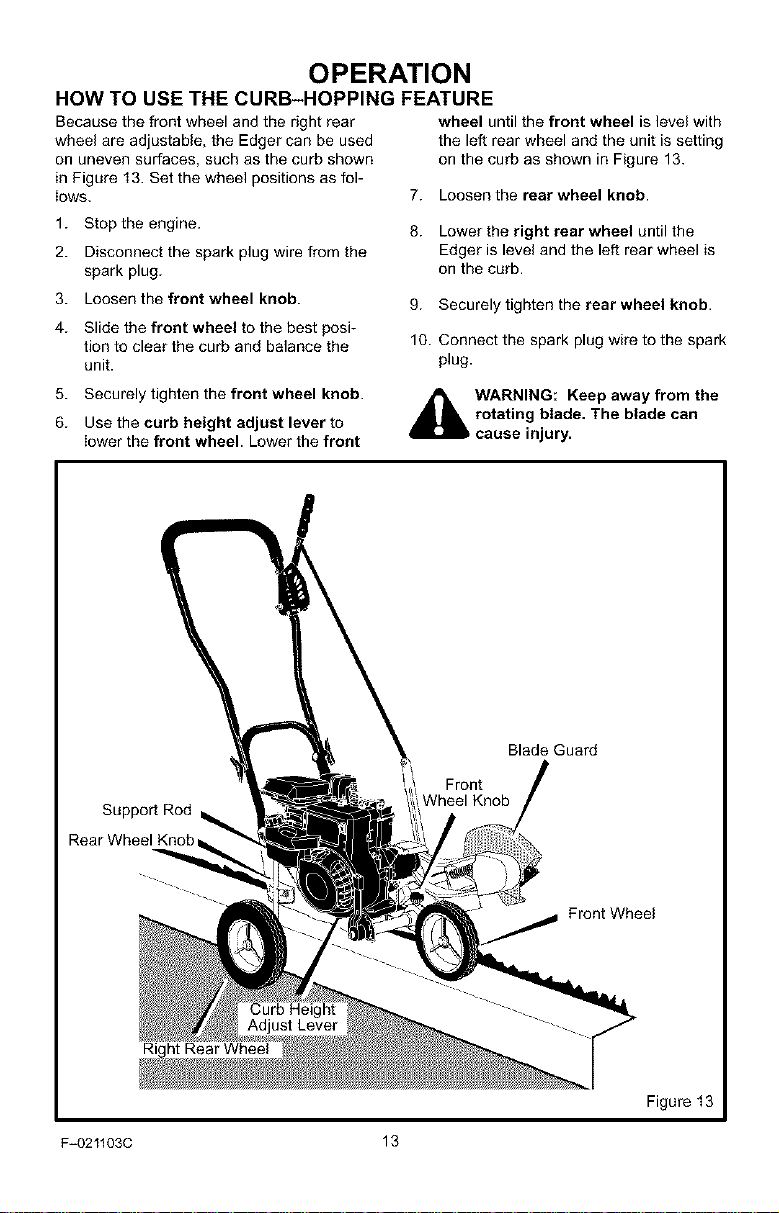
HOW TO USE THE CURB-HOPPING FEATURE
Because the front wheel and the right rear
wheel are adjustable, the Edger can be used
on uneven surfaces, such as the curb shown
in Figure 13. Set the wheel positions as fol-
iows.
1. Stop the engine.
2. Disconnect the spark plug wire from the
spark plug.
3. Loosen the front wheel knob.
4. Slide the front wheel to the best posi-
tion to clear the curb and balance the
unit.
5. Securely tighten the front wheel knob.
6. Use the curb height adjust lever to
lower the front wheel. Lower the front
wheel until the front wheel is level with
the left rear wheel and the unit is setting
on the curb as shown in Figure 13.
7. Loosen the rear wheel knob.
8. Lower the right rear wheel until the
Edger is level and the left rear wheel is
on the curb.
9. Securely tighten the rear wheel knob.
10. Connect the spark plug wire to the spark
plug.
_k ARNING: Keep away from the
rotating blade. The blade can
cause injury.
Rear Wheel Knob
ht Rear Wheel
F_021103C 13
Blade Guard
Front
Wheel Knob
Front Wheel
Figure 13
OPERATION
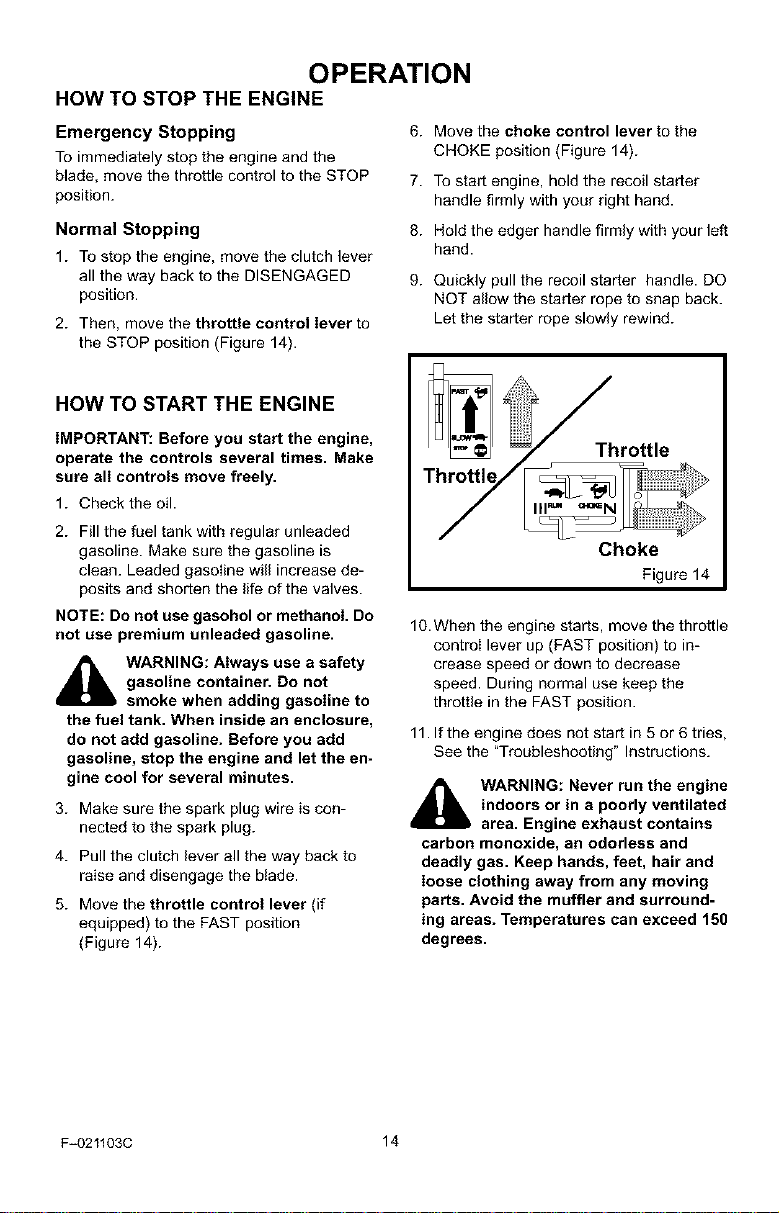
HOW TO STOP THE ENGINE
Emergency Stopping
To immediately stop the engine and the
blade, move the throttle control to the STOP
position.
Normal Stopping
1. To stop the engine, move the clutch lever
all the way back to the DISENGAGED
position.
2. Then, move the throttle control lever to
the STOP position (Figure 14).
HOW TO START THE ENGINE
IMPORTANT: Before you start the engine,
operate the controls several times. Make
sure all controls move freely.
1. Check the oil.
2. Fill the fuel tank with regular unleaded
gasoline. Make sure the gasoline is
clean. Leaded gasoIine will increase de-
posits and shorten the life of the valves.
NOTE: Do not use gasohol or methanol. Do
not use premium unleaded gasoline.
_lb ARNING: Always use a safety
3. Make sure the spark plug wire is con-
4. Pull the clutch lever all the way back to
5. Move the throttle control lever (if
gasoline container. Do not
smoke when adding gasoline to
the fuel tank. When inside an enclosure,
do not add gasoline. Before you add
gasoline, stop the engine and let the en-
gine cool for several minutes.
nected to the spark plug.
raise and disengage the btade.
equipped) to the FAST position
(Figure 14).
6. Move the choke control lever to the
CHOKE position (Figure 14).
7. To start engine, hold the recoil starter
handle firmly with your right hand.
8. Hold the edger handle firmly with your left
hand.
9. Quickly pull the recoil starter handle. DO
NOT allow the starter rope to snap back.
Let the starter rope slowly rewind.
_Throttle
Choke
Figure14
10.When the engine starts, move the throttle
controI lever up (FAST position) to in-
crease speed or down to decrease
speed. During normal use keep the
throttle in the FAST position.
11. If the engine does not start in 5 or 6 tries,
See the "Troubleshooting" Instructions.
_ ARNING: Never run the engine
indoors or in a poorly ventilated
area. Engine exhaust contains
carbon monoxide, an odorless and
deadly gas. Keep hands, feet, hair and
loose clothing away from any moving
parts. Avoid the muffler and surround-
ing areas. Temperatures can exceed 150
degrees.
F=021103C 14
OPERATION
EDGING TIPS
• Edging is best performed when conditions
are dry. If the soil is to wet, dirt becomes
packed around the blade causing prema-
ture belt wear and decreased perfor-
mance.
• If dirt does become packed around the
blade, stop the engine and remove the
wire from the spark plug. Remove the
packed dirt and debris from the blade.
• For deep edging, first cut at shallow
depths. Then, cut at greater depths until
the desired depth is obtained.
• For uniform edging, make sure the blade
guide rides on the surface.
• Edging can be customized by varying the
number of passes and by the distance the
blade is from the surface.
manual. Know location and
WARNING: Read the Owner's
functions of all controls. Keep
all safety devices and shields in place.
Never allow children or uninstructed
adults to operate Edger. Shut off engine
before unclogging blade or making re-
pairs. Keep bystanders away from ma=
chine. Keep away from the blade and all
rotating parts, which cause injury.
F_021103C 15
MAINTENANCE
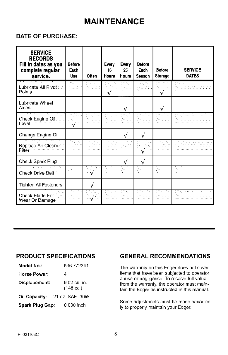
DATE OF PURCHASE:
SERVICE
RECORDS
Fill in dates as you Before Every Every Before
complete regular Each 10 25 Each Before SERVICE
service. Use Often Hours Hours Season Storage DATES
Lubricate All Pivot
Points
Lubricate Wheel
Axles
Check Engine Oil
Level _/
Change Engine Oil
Replace Air Cleaner
Filter
Check Spark Plug _/ _/
Tighten AII Fasteners
i
I
I I I I
I I I
, , , , ,
ill i i
i i i
Check Blade For I I _ I
Wear Or Damage *7 ....
PRODUCT SPECIFICATIONS
Model No.: 530.772341
Horse Power: 4
Displacement: 9.02 cu. in.
(148 cc.)
Oil Capacity: 21 oz. SAE-3OW
Spark Plug Gap: 0.030 inch
F_021103C 16
GENERAL RECOMMENDATIONS
The warranty on this Edger does not cover
items that have been subjected to operator
abuse or negligence. To receive full value
from the warranty, the operator must main-
tain the Edger as instructed in this manual.
Some adjustments must be made periodical-
ly to properly maintain your Edger.
MAINTENANCE
LUBRICATION
After each 25 hours, apply a small amount of
engine oil to all moving parts, particularly the
wheels.
How To Change The Engine Oil
Change the oil in the engine crankcase after
each 25 hours of use.
NOTE: The oil will drain more freely when
the engine is warm.
1. Disconnect the spark plug wire from the
spark plug.
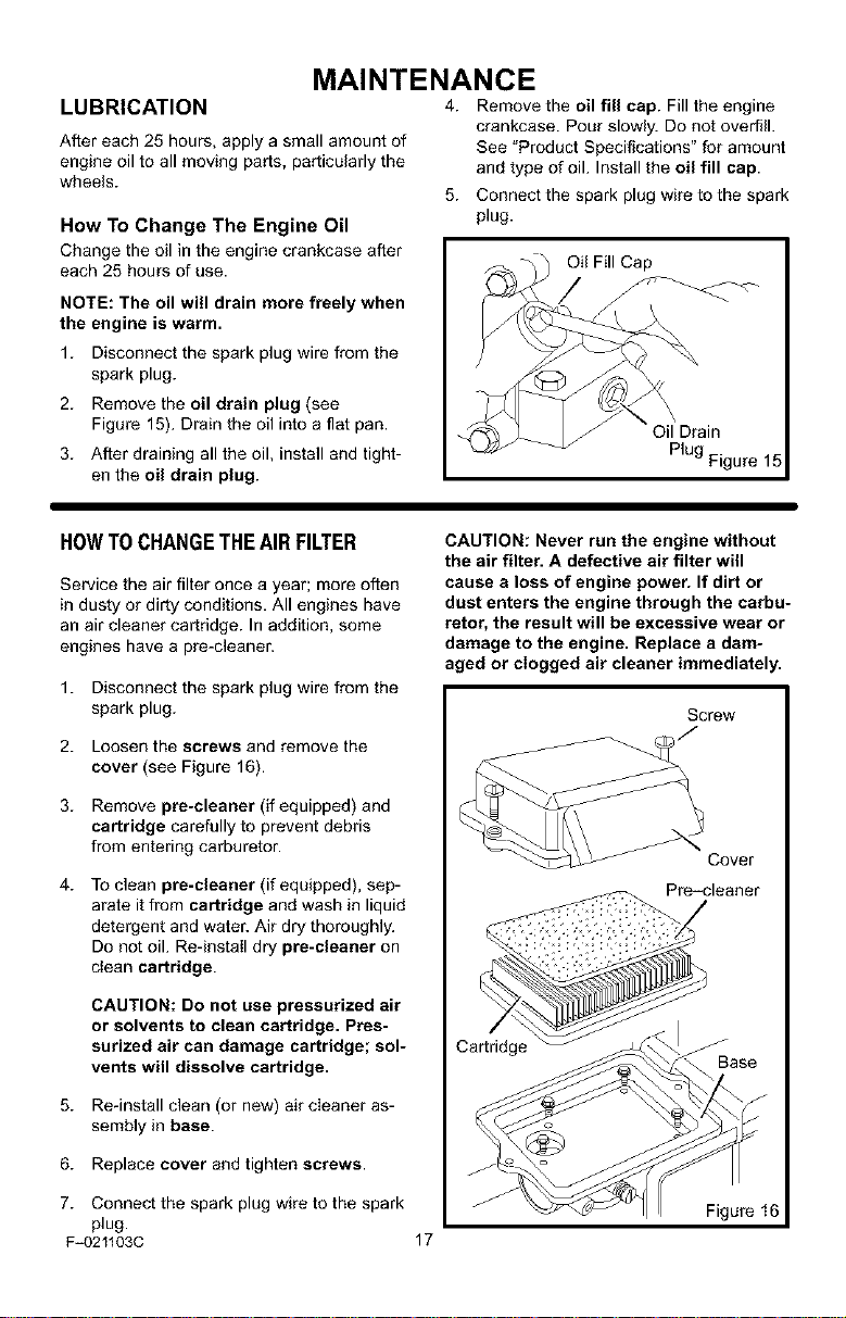
2. Remove the oil drain plug (see
Figure 15). Drain the oil into a flat pan.
3. After draining all the oil, install and tight-
en the oil drain plug.
4. Remove the oil fill cap. Fill the engine
crankcase. Pour slowly. Do not overfill.
See "Product Specifications" for amount
and type of oil. Install the oil fill cap.
5. Connect the spark plug wire to the spark
plug.
Oil Fill Cap
Plug Figure 15
HOWTOCHANGETHEAIR FILTER
Service the air filter once a year; more often
in dusty or dirty conditions. All engines have
an air cleaner cartridge. In addition, some
engines have a pre-cleaner.
1. Disconnect the spark plug wire from the
spark plug.
2. Loosen the screws and remove the
cover (see Figure 16).
3. Remove pre-cleaner (if equipped) and
cartridge carefully to prevent debris
from entering carburetor.
4. To clean pre-cleaner (if equipped), sep-
arate it from cartridge and wash in liquid
detergent and water. Air dry thoroughly.
Do not oil. Re-install dry pre-cleaner on
dean cartridge.
CAUTION: Do not use pressurized air
or solvents to clean cartridge. Pres-
surized air can damage cartridge; sol-
vents will dissolve cartridge.
5. Re-install clean (or new) air cleaner as-
sembly in base.
6. Replace cover and tighten screws.
CAUTION: Never run the engine without
the air filter. A defective air filter will
cause a loss of engine power. If dirt or
dust enters the engine through the carbu-
retor, the result will be excessive wear or
damage to the engine. Replace a dam-
aged or clogged air cleaner immediately.
Screw
Cover
Pre-cleaner
Cartridge
7. Connect the spark plug wire to the spark Figure 16
plug.
F_021103C 17
MAINTENANCE
SPARK PLUG
Check the spark plug every 25 hours. Re-
place the spark plug if the electrodes are
pitted, burned, or if the porcelain is cracked.
1. Make sure the spark plug is clean.
Clean the spark plug by carefully scrap-
ing the electrodes (do not sand blast or
use a wire brush).
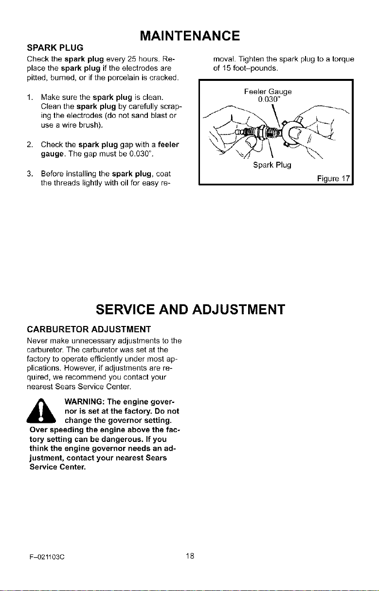
2. Check the spark plug gap with a feeler
gauge. The gap must be 0.030".
3. Before installing the spark plug, coat
the threads lightly with oil for easy re-
SERVICE AND ADJUSTMENT
moval. Tighten the spark plug to a torque
of 15 foot-pounds.
Feeler Gauge
0.030"
Spark Plug
Figure I
CARBURETOR ADJUSTMENT
Never make unnecessary adjustments to the
carburetor. The carburetor was set at the
factory to operate efficiently under most ap-
plications. However, if adjustments are re-
quired, we recommend you contact your
nearest Sears Service Center.
_lb WARNING: The engine gover-
Over speeding the engine above the fac-
tory setting can be dangerous. If you
think the engine governor needs an ad-
justment, contact your nearest Sears
Service Center.
F-021103C 18
nor is set at the factory. Do not
change the governor setting.
SERVICE AND ADJUSTMENT
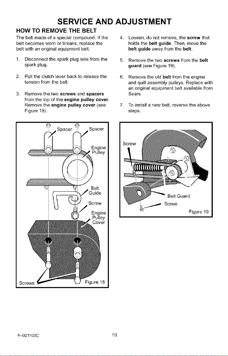
HOW TO REMOVE THE BELT
The belt made of a special compound, if the 4. Loosen, do not remove, the screw that
belt becomes worn or breaks, replace the holds the belt guide. Then, move the
belt with an original equipment belt. belt guide away from the belt.
1. Disconnect the spark plug wire from the
spark plug.
5. Remove the two screws from the belt
guard (see Figure 19).
2. Pull the clutch lever back to release the
tension from the belt.
3. Remove the two screws and spacers
from the top of the engine pulley cover.
Remove the engine pulley cover (see
Figure 18).
@
6.
Remove the old belt from the engine
and quill assembly pulleys. Replace with
an original equipment belt available from
Sears.
7. To install a new belt, reverse the above
steps.
Belt Guard
_ Screw
Figure 19
Screws Figure 18
F-021103C 19
SERVICE AND ADJUSTMENT
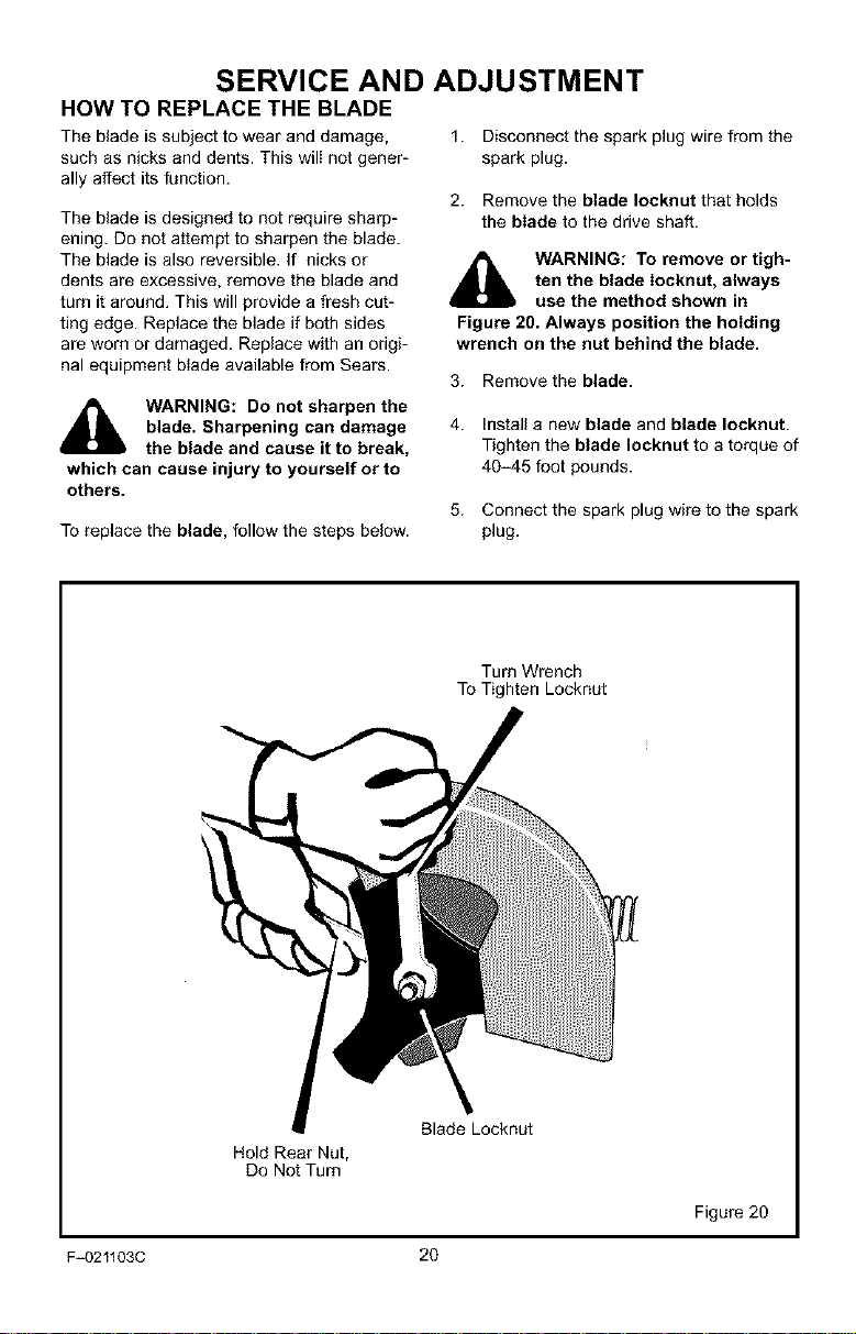
HOW TO REPLACE THE BLADE
The blade is subject to wear and damage,
such as nicks and dents. This will not gener-
ally affect its function.
The blade is designed to not require sharp-
ening. Do not attempt to sharpen the blade.
The blade is also reversible. If nicks or
dents are excessive, remove the blade and
turn it around. This will provide a fresh cut-
ting edge. Replace the blade if both sides
are worn or damaged. Replace with an origi-
nal equipment btade available from Sears.
1. Disconnect the spark plug wire from the
spark plug.
2. Remove the blade Iocknut that holds
the blade to the drive shaft.
,_ WARNING: To remove or tigh-
Figure 20. Always position the holding
wrench on the nut behind the blade.
3. Remove the blade.
ten the blade Iocknut, always
use the method shown in
blade. Sharpening can damage
WARNING: Do not sharpen the
the blade and cause it to break,
which can cause injury to yourself or to
others.
To replace the blade, follow the steps below.
4. Install a new blade and blade Iocknut.
Tighten the blade Iocknut to a torque of
40-45 foot pounds.
5. Connect the spark plug wire to the spark
plug.
Turn Wrench
To Tighten Locknut
Hold Rear Nut,
Do Not Turn
F-021103C 20
Blade Locknut
Figure 20
 Loading...