

Craftsman 48624717 Owner’s Manual

Operator's IVlanuai
CRnFTSMRH°
PROFESSIONAL CHIP-N-VAC
Model No. 486.24717
DO NOT RETURN TO STORE
For Missing Parts or Assembly
Questions Call 1-866-576-8388
CAUTION:
Before using this product, read
this manual and follow all Safety
Rules and Operating Instructions.
,, Safety
,, Assembly
,, Operation
,, Maintenance
,, Parts
Sears, Roebuck and Co., Hoffman Estates, IL 60179 U.S.A.
www.sears.com/craftsman
PRINTED IN U.S.A. FORM NO. 26633 (08/13/08)

WARRANTY ................................................................ 2
SAFETY RULES .......................................................... 3
FULL SIZE HARDWARE CHART ................................ 6
CARTON CONTENTS ................................................. 7
ASSEMBLY .................................................................. 8
OPERATION .............................................................. 16
MAINTENANCE ........................................................ 18
SERVICE AND ADJUSTMENTS ............................... 19
STORAGE ................................................................. 19
TROUBLESHOOTING ............................................... 20
REPAIR PARTS ILLUSTRATIONS ................. 23,24,26
REPAIR PARTS LISTS .................................... 23,25,26
SLOPE GUIDE .......................................................... 27
PARTS ORDERING/SERVICE .................... Rear Cover
CRAFTSMAN PROFESSIONAL LiMiTED WARRANTY
Two Years on Powered Tractor Attachment
When operated and maintained according to all supplied instructions, if this Powered Attachment fails due to a defect in
material or workmanship within two years from the date or purchase, call 1-800-4-MY-HOME® to arrange for free repair.
This warranty applies for only one year from the date of purchase if this Powered Attachment is ever used for commercial
or rental purposes.
During the first year of purchase, there will be no charge for warranty service in your home. For your convenience, in-
home warranty service will still be available after the first year of purchase, but a trip charge will apply. This charge will be
waived if you transport the tractor to an authorized Craftsman drop-off location. For the nearest authorized location, call
1-800-4-MY-HOME®.
This warranty covers ONLY defects in material and workmanship. Sears wii[ NOT pay for:
• Expendable items that become worn during normal use, including but not limited to blades, spark plugs, air cleaners,
belts, and oil filters.
Standard maintenance servicing, oil changes, or tune-ups.
Tire replacement or repair caused by punctures from outside objects, such as nails, thorns, stumps, or glass.
Tire or wheel replacement or repair resulting from normal wear, accident, or improper operation or maintenance.
Repairs necessary because of operator abuse, including but not limited to damage caused by improper transportation,
impacting objects that bend the frame or crankshaft, or over-speeding the engine.
Repairs necessary because of operator negligence, including but not limited to, electrical and mechanical damage
caused by improper storage, failure to use the proper grade and amount of engine oil, failure to keep the deck clear of
flammable debris, or failure to maintain the equipment according to the instructions contained in the operator's manual.
Engine (fuel system) cleaning or repairs caused by fuel determined to be contaminated or oxidized (stale). in general,
fuel should be used within 30 days of its purchase date.
Normal deterioration and wear of the exterior finishes, or product label replacement.
This warranty applies only while this product is within the United States.
This warranty gives you specific legal rights, and you may also have other rights which vary from state to state.
Sears, Roebuck and Co., Hoffman Estates, iL 60179
2 Call 1-866-576-8388 for missing parts or assembly help
DO NOT RETURN TO STORE
Any power equipment can cause injury if operated improperly or if the user does not understand how to operate the equipment. Exercise
caution at all times, when using power equipment.
• Read and follow all instructions inthis manual before attempting
to assemble or operate this equipment. Failure to comply
with these instructions may result in personal injury. Keep this
manual in a safe place for future reference and for ordering
replacement parts.
Read this operating and service instruction manual carefully.
Be thoroughly familiar with the controls and proper use of this
power vacuum.
Read the vehicle owners manual and vehicle safe operation
rules before using this equipment.
Never allow children under 16 to operate this Chipper Vac.
Children 16 years and older should only operate under close
parental supervision.
Do not allow anyone to operate this equipment without proper
instructions.
Do not allow passengers to ride on this equipment or on the
towing vehicle.
Keep the area of operation clear of all persons, particularly
small children. Also keep area clear of pets.
Check fuel before starting engine. Do not fill fuel tank indoors,
or when engine is running, or while engine is hot. Wipe off any
spilled fuel before starting engine.
Engine and muffler get hot. Do not touch! To avoid fire hazard,
keep clean of debris and other accumulations.
Never store Chipper Vac with fuel in tank. Allow engine to coot
before storing in any enclosure.
Do not change engine governor settings.
Do not operate engine if air cleaner or cover is removed,
except for adjustment. Removal of these parts could create a
fire hazard.
Before cleaning, repairing or inspecting, make certain all moving
parts come to a complete stop. Disconnect spark plug wire and
keep wire away from plug to prevent accidental starting. Keep
throttle control lever in stop position.
If the Chipper Vac should become blocked with debris at any
point, shut engine off and wait until the impeller comes to a
complete stop before attempting to remove the obstruction.
Disconnect spark plug wire to prevent accidental starting.
If the cutting mechanism strikes a foreign object, or if your
ChipperVac should start to vibrate abnormally, stop the engine
immediately, disconnect the spark plug wire and move the wire
away from the spark plug. Allow the machine to stop and take
the following steps.
a. Inspect for damage.
b. Repair or replace any damaged parts.
c. Check for loose parts and tighten to assure
continued safe operation.
Check all bolts for tightness at frequent intervals to help insure
safe operation.
Check vinyl hard top boot frequently for wear. Replace if worn
or damaged.
Never operate Chipper Vac unless deck adapter, hose, hose
adapter (nozzle), discharge chute (elbow), chipper chute and
top cover are properly attached in their place.
Do not remove top cover or attempt to empty contents of cart
while engine is running.
Never attempt to change hose adapter (nozzle) or to install
remote hose attachment when engine is running.
Keep all shields and guards (e.g. chipper chute, discharge
chute (elbow) and hose adapter (nozzle) in place and securely
attached.
Keep hands, feet, face, long hair and clothing out of inlet and
discharge area. There are ROTATING BLADES inside these
openings.
Always wear safety glasses or other suitable eye protection
when operating or maintaining this equipment.
Wear protective gloves when feeding material into the chipper
chute. Avoid loose fitting clothing.
Keep face and body clear of the chipper chute toavoid accidental
bounce back of any material.
When feeding material into this equipment, be extremely careful
that pieces of metal, rocks, bottles, cans or other foreign objects
are not included. Personal injury or damage to the machine
could result.
Do not stand behind cart in exhaust discharge area while
engine is running.
Do not operate this equipment while intoxicated or while taking
drugs or medication that impairs the senses and reactions.
When using this equipment, start with the vehicle transmission
in first (low) gear and then gradually increase speed only as
conditions permit.
Operate this equipment at reduced speed on rough terrain,
along creeks and ditches and on slopes to prevent tipping or
loss of control. Do not drive too close to a creek or ditch.
Vehicle braking and stability are affected by the addition of
this equipment. Do not fill the Chipper Vac to its full capacity
without checking the capability of the towing vehicle to safely
pull and stop with the Chipper Vac attached.
Before operating on any grade (hilt) refer to the safety rules
in the vehicle owner's manual concerning safe operation on
slopes. Also refer to the SLOPE GUIDE on page 27 of this
owner's manual. Do not operate on slopes in excess of 10
degrees. STAY OFF STEEP SLOPES.
Follow the maintenance instructions outlined in this manual.
Look for this symbol to point out important safety precautions. It means-- Attention!! Become alert!! Your safety
is involved.
DANGER: This Chipper Vac was built to be operated according to the rules for safe operation in this
manual. As with any type of power equipment, carelessness or error on the part of the operator can
result in serious injury. This unit is capable of amputating fingers and hands and throwing objects.
Failure to observe the following safety instructions could result in serious injury or death.
Call 1-866-576-8388 for missing parts or assembly help 3
DO NOT RETURN TO STORE

TO AVOID SERIOUS iNJURY
• Read Owner's Manual and all safety labels on machine before starting and using machine.
• Do Not remove top cover or attempt to empty contents of cart while engine is running.
• Do Not stand behind cart in exhaust discharge area while engine is running.
• Keep hands, feet, face, long hair and clothing out of chipper inlet, vac inlet, and discharge
area. There are ROTATING BLADES inside these openings.
• Wear approved safety glasses and gloves. Avoid loose fitting clothes.
• Keep the area of operation clear of all persons, particularly small children and pets.
• Keep all shields and guards (e.g. upper chipper chute extension, discharge chute, nozzle
assembly) in place and securely attached.
• Check discharge boot frequently for wear. Replace if worn or damaged.
• if unit becomes clogged or jammed, shut off engine right away. Do Not attempt to clear
clog or jam with engine running.
• Muffler and engine get hot and can cause burns. Do Not Touch. To avoid a fire hazard,
keep leaves, grass and other combustible debris off hot muffler and engine.
• Do Not attempt to remove or attach vac nozzle or optional Hose Kit with engine running.
• Do Not operate unit unless nozzle or optional Hose Kit is secured in place.
• Do Not fill gas tank while engine is running. Allow engine to cool at least 2 minutes
before refueling.
ROTATING CUTTING BLADES.
KEEP HANDS AND FEET OUT
OF OPENINGS WHILE MACHINE
iS RUNNING.
WA I
This unit is equipped with an internal combustion engine and should not be used on or near unimproved forest-covered, or
grass-covered land unless the engine's exhaust system is equipped with a spark arrester meeting applicable local or state
laws (if any). If a spark attester is used, it should be maintained in effective working order by the operator.
In the State of California the above is required by law (Section 4442 of the California Public Resources Code). Other
states may have similar laws. Federal laws apply on federal lands. A spark attester muffler is available at your nearest
engine authorized service center.
4 Call 1-866-576-8388 for missing parts or assembly help
DO NOT RETURN TO STORE
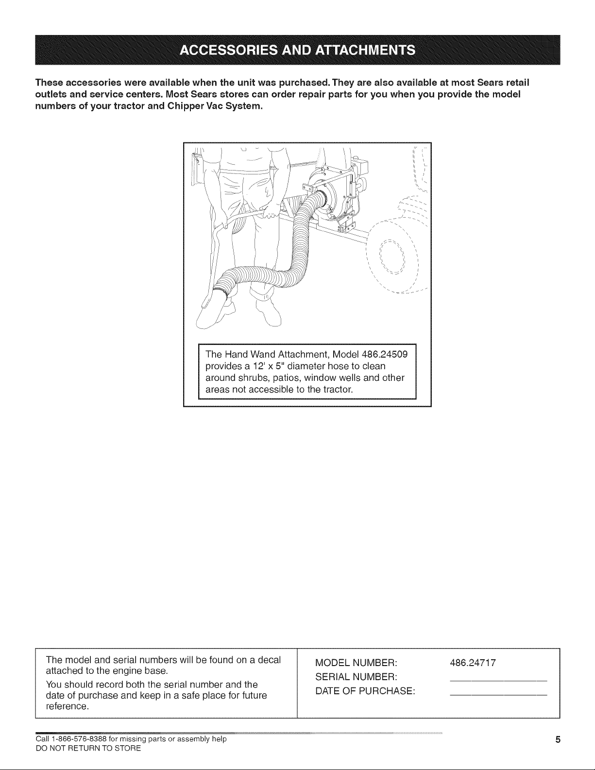
These accessories were available when the unit was purchased. They are also available at most Sears retail
outlets and service centers. Most Sears stores can order repair parts for you when you provide the model
numbers of your tractor and Chipper Vac System.
\
\
/
\
\
The Hand Wand Attachment, Model 486.24509
provides a 12' x 5" diameter hose to clean
around shrubs, patios, window wells and other
areas not accessible to the tractor.
The model and serial numbers will be found on a decal
attached to the engine base.
You should record both the serial number and the
date of purchase and keep in a safe place for future
MODEL NUMBER:
SERIAL NUMBER:
DATE OF PURCHASE:
486.24717
reference.
Cal11-866-576-8388formissingpartsorassemblyhelp 5
DO NOT RETURN TO STORE
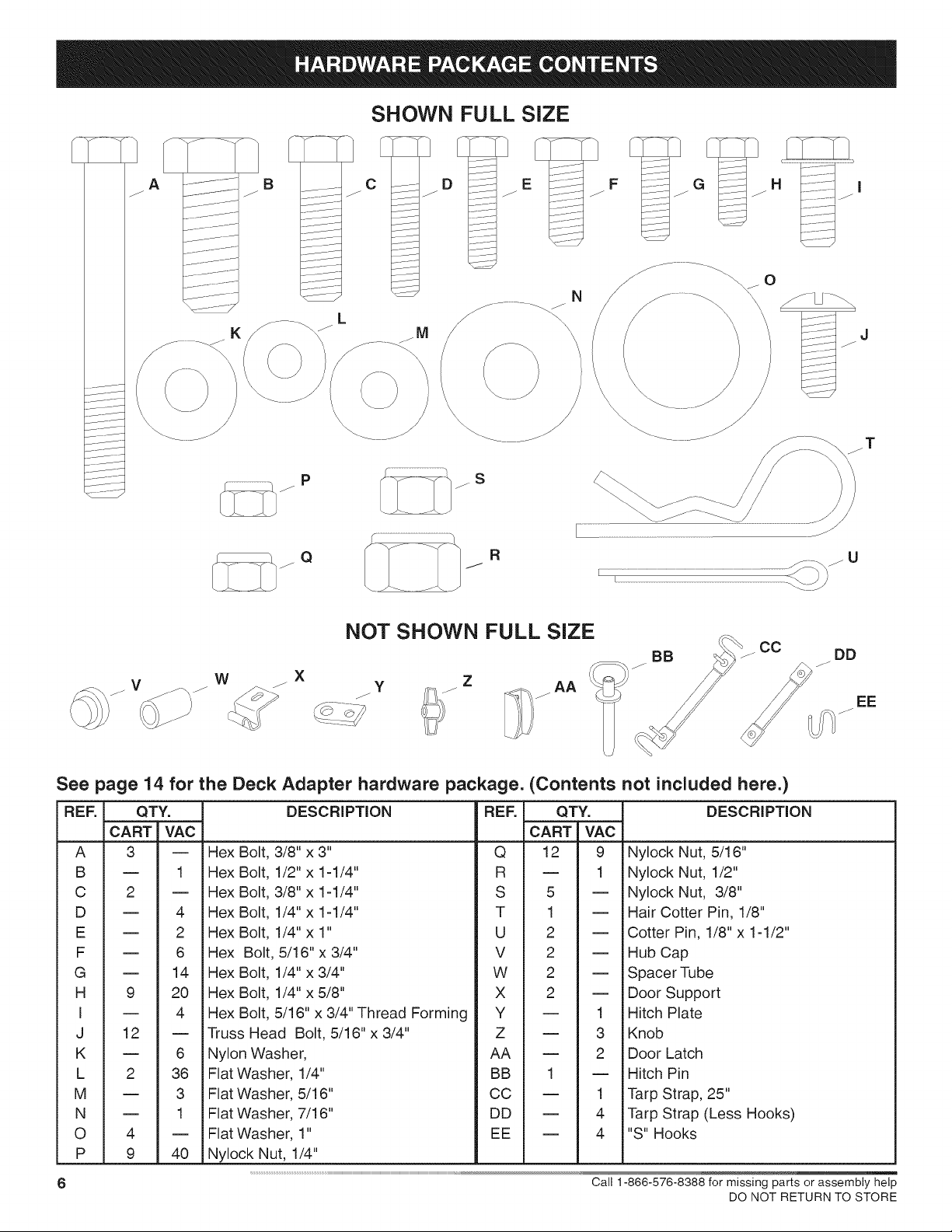
SHOWN FULL SIZE
A -J B
/ / /
j ........
K
W J X y Z AA
C D E I---:--:---_ F G H i
..... J
p S
Q R
NOT SHOWN FULL SIZE
/ /
_.._ -.............._
/
N
0
\
\
r..................................................................................................................................................................................................................._=.<_j U
CC
/
DD
/
EE
See page 14 for the Deck Adapter hardware package. (Contents not included here.)
REF. QTY.
CART VAC
A 3 --
B -- 1
C 2 --
D -- 4
E -- 2
F -- 6
G -- 14
H 9 20
I -- 4
J 12 --
K = 6
L 2 36
M = 3
N = 1
O 4 =
P 9 40
6 Call 1-866-576-8388 for missing parts or assembly help
iHex
iHex
iHex
iHex
iHex
Hex
iHex
iHex Bolt, 1/4" x 5/8"
iHex Bolt, 5/16" x 3/4" Thread Forming
Truss Head Bolt, 5/16"x 3/4"
iNylon Washer,
Flat Washer, 1/4"
Flat Washer, 5/16"
Flat Washer, 7/16"
Flat Washer, 1"
iNylock Nut, 1/4"
DESCRiPTiON
Bolt, 3/8" x 3"
Bolt, 1/2" x 1-1/4"
Bolt, 3/8" x 1-1/4"
Bolt, 1/4" x 1-1/4"
Bolt, 1/4"x 1"
Bolt, 5/16"x 3/4"
Bolt, 1/4" x 3/4"
REF. QTY. DESCRiPTiON
CART VAC
Q 12 9 Nylock Nut, 5/16"
R -- 1 Nylock Nut, 1/2"
S 5 -- Nylock Nut, 3/8"
T 1 -- Hair Cotter Pin, 1/8"
U 2 -- Cotter Pin, 1/8"x 1-1/2"
V 2 -- Hub Cap
W 2 -- Spacer Tube
X 2 -- Door Support
Y -- 1 Hitch Plate
Z -- 3 Knob
AA -- 2 Door Latch
BB 1 -- Hitch Pin
CC -- 1 Tarp Strap, 25"
DD -- 4 Tarp Strap (Less Hooks)
EE -- 4 "S" Hooks
DO NOT RETURN TO STORE
1
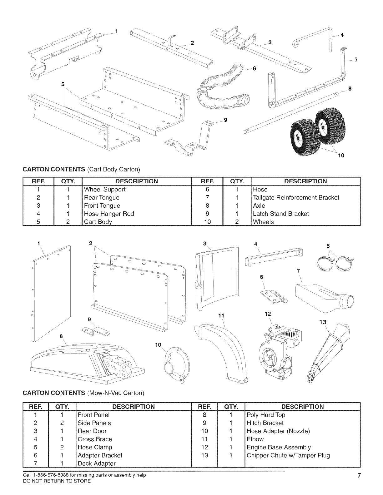
CARTON CONTENTS (Cart Body Carton)
REF.
1
2 1
3 1
4 1
5 2
QTY. DESCRIPTION
1 Wheel Support
Rear Tongue
Front Tongue
Hose Hanger Rod
Cart Body
_9
REF. QTY, DESCRIPTION
6 1 Hose
7
8
9
10
1
Tailgate Reinforcement Bracket
1
Axle
1
Latch Stand Bracket
2
Wheels
10
1
\
\
CARTON CONTENTS (Mow-N-Vac Carton)
RER QT_
1 1
2 2
3 1
4 1
5 2
6 1
7 1
Front Panel
Side Panels
Rear Door
Cross Brace
Hose Clamp
Adapter Bracket
Deck Adapter
DESCRIPTION
3
11
\
\
RER QT_
8 1
9 1
10 1
11 1
12 1
13 1
7
6
12
\
\,
13
DESCRIPTION
i Poly Hard Top
Hitch Bracket
Hose Adapter (Nozzle)
Elbow
i Engine Base Assembly
Chipper Chute w/Tamper Plug
5
m _ /_ s
\
Cal11-866-576-8388formissingpartsorassemblyhelp 7
DO NOT RETURN TO STORE
This unit is shipped WITHOUT GASOLINE or OIL. After
assembly, see separate engine manual for proper fuel
and engine oil recommendations.
TOOLS REQUIRED FOR ASSEMBLY
(1) Screwdriver
(!) Pliers
(2) 7/16" Wrenches
(2) 1/2" Wrench
(2) 9/16" Wrenches
(2) 3/4" Wrenches (only if figure 23 on page 12 is used)
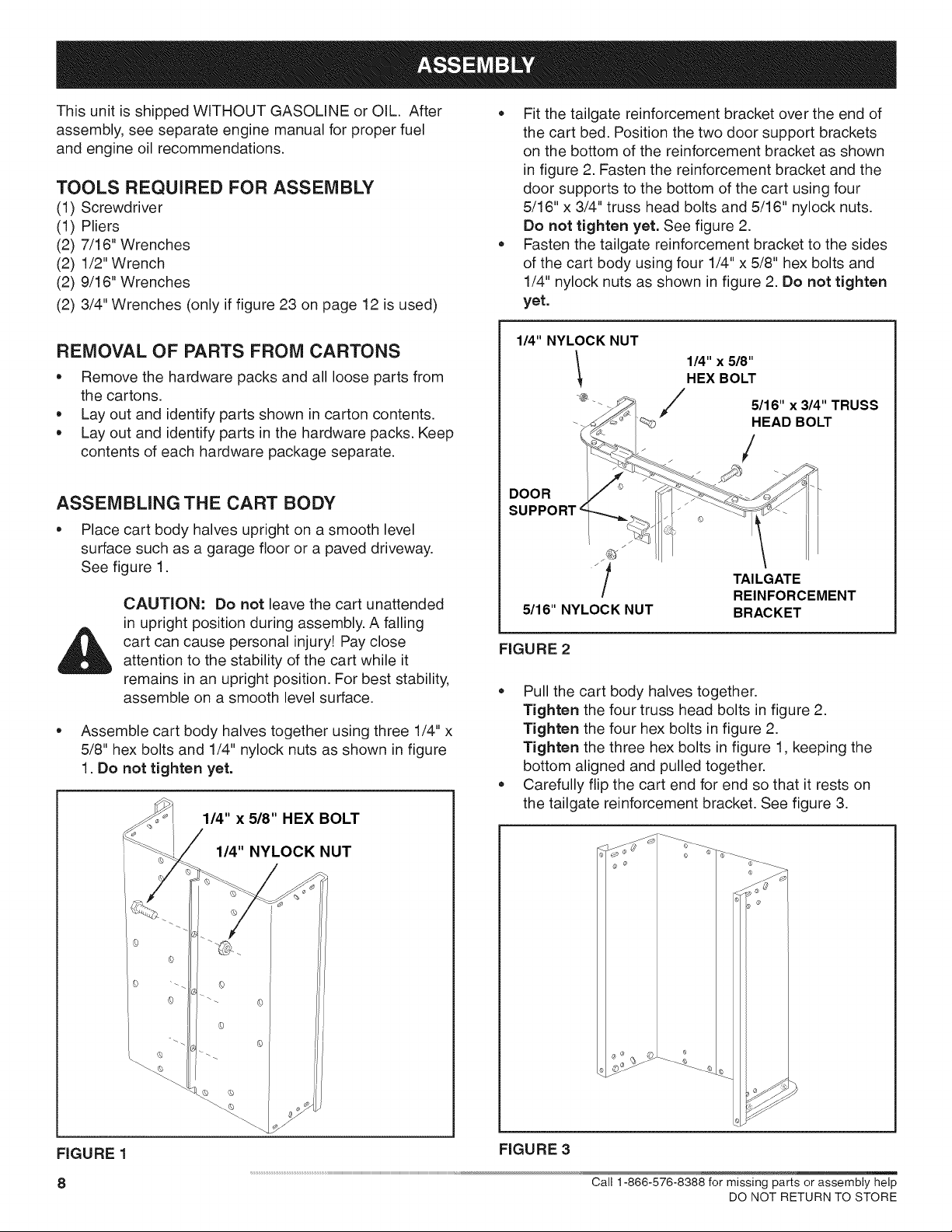
• Fit the tailgate reinforcement bracket over the end of
the cart bed. Position the two door support brackets
on the bottom of the reinforcement bracket as shown
in figure 2. Fasten the reinforcement bracket and the
door supports to the bottom of the cart using four
5/16" x 3/4" truss head bolts and 5/16" nylock nuts.
Do not tighten yet. See figure 2.
• Fasten the tailgate reinforcement bracket to the sides
of the cart body using four 1/4" x 5/8" hex bolts and
1/4" nylock nuts as shown in figure 2. Do not tighten
yet.
REMOVAL OF PARTS FROM CARTONS
Remove the hardware packs and all loose parts from
the cartons.
Lay out and identify parts shown in carton contents.
Lay out and identify parts in the hardware packs. Keep
contents of each hardware package separate.
ASSEMBLING THE CART BODY
Place cart body halves upright on a smooth level
surface such as a garage floor or a paved driveway.
See figure 1.
CAUTION: Do not leave the cart unattended
in upright position during assembly. A falling
cart can cause personal injury! Pay close
attention to the stability of the cart while it
remains in an upright position. For best stability,
assemble on a smooth level surface.
Assemble cart body halves together using three 1/4" x
5/8" hex bolts and 1/4" nylock nuts as shown in figure
1. Do not tighten yet.
1/4" x 5/8" HEX BOLT
1/4" NYLOCK NUT
1/4" x 5/8"
HEX BOLT
,#
/ 5116"x 314"TRUSS
p-
-_' HEAD BOLT
/
DOOR
SUPPORT
t TAILGATE
/
5116"NYLOCKNUT BRACKET
FIGURE 2
Pull the cart body halves together.
Tighten the four truss head bolts in figure 2.
Tighten the four hex bolts in figure 2.
Tighten the three hex bolts in figure 1, keeping the
bottom aligned and pulled together.
Carefully flip the cart end for end so that it rests on
the tailgate reinforcement bracket. See figure 3.
REINFORCEMENT
FIGURE 1
8
1/4" NYLOCK NUT
FIGURE 3
Call 1-866-576-8388 for missing parts or assembly help
DO NOT RETURN TO STORE
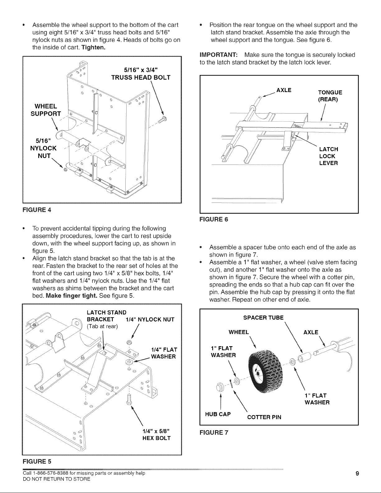
Assemble the wheel support to the bottom of the cart
using eight 5/16" x 3/4" truss head bolts and 5/16"
nylock nuts as shown in figure 4. Heads of bolts go on
the inside of cart. Tighten.
5/16" x 3/4"
TRUSS HEAD BOLT
* Position the rear tongue on the wheel support and the
latch stand bracket. Assemble the axle through the
wheel support and the tongue. See figure 6.
iMPORTANT: Make sure the tongue is securely locked
to the latch stand bracket by the latch lock lever.
WHEEL
SUPPORT
5/16"
NYLOCK _
NUT
FIGURE 4
To prevent accidental tipping during the following
assembly procedures, lower the cart to rest upside
down, with the wheel support facing up, as shown in
figure 5.
Align the latch stand bracket so that the tab is at the
rear. Fasten the bracket to the rear set of holes at the
front of the cart using two 1/4" x 5/8" hex bolts, 1/4"
flat washers and 1/4" nylock nuts. Use the 1/4" flat
washers as shims between the bracket and the cart
bed. Make finger tight. See figure 5.
AXLE
FIGURE 6
o
Assemble a spacer tube onto each end of the axle as
shown in figure 7.
o
Assemble a 1" flat washer, a wheel (valve stem facing
out), and another 1" flat washer onto the axle as
shown in figure 7. Secure the wheel with a cotter pin,
spreading the ends so that a hub cap can fit over the
pin. Assemble the hub cap by pressing it onto the flat
washer. Repeat on other end of axle.
TONGUE
LATCH STAND
BRACKET 1/4" NYLOCK NUT
(Tab at rear) /
\
FIGURE 5
Call 1-866-576-8388 for missing parts or assembly help
DO NOT RETURN TO STORE
1/4" FLAT
1/4" x 5/8"
HEX BOLT
1" FLAT \
WASHER
T
HUBCAP
FIGURE 7
SPACER TUBE
WHEEL
\
AXLE
\
1" FLAT
WASHER
COTTER PIN
9
 Loading...