

Craftsman 48624505 Owner’s Manual
OWNERS MANUAL
CRflFTSMRN°
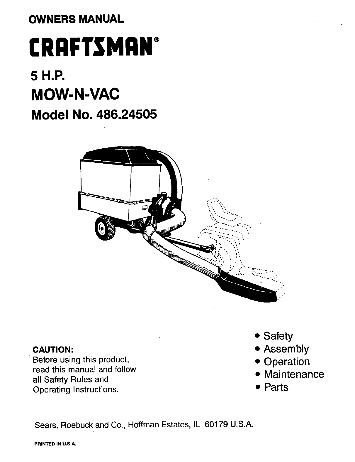
5 H.P.
MOW-N-VAC
Model No. 486.24505
CAUTION:
• Before using this product,
read this manual and follow
all Safety Rules and
Operating Instructions.
Sears, Roebuck and Co., Hoffman Estates, IL 60179 U.S.A.
PRINTED IN U.S.A.
• Safety
• Assembly
• Operation
• Maintenance
• Parts
ACCESSORIES ......................................................... 2
SAFETY RULES .................................................... 3,4
FULL SIZE HARDWARE CHART ......................... 5,6
CARTON CONTENTS .............................................. 6
ASSEMBLY ................ _.......... !,.....!.._. .............. _........ 7
OPERATION ........................................................ ;.. 18
MAINTENANCE ...................................................... 19
STORAGE ............................................................... 20
TROUBLESHOOTING ............................................ 20
PARTS ................................................................ 23-25
SLOPE GUIDE ........................................................ 27
PARTS ORDERING/SERVICE ................. Back Page
LIMITED ONEYEAR WARRANTY: ON
For one year from the date of purchase, when this Mow-N-Vac is maintained and lubricated according to the operating and
maintenance instructions in the owner's manual, Sears will repair any defect in material or workmanship free of charge.
If this Mow-N-Vac is used for commercial or rental purposes_ this warranty applies for only 90 days from the date of
purchase.
This warranty does not cover repairs necessary because of operator negligence or abuse, includingthe failure to maintain
the equipment according to instructions contained in the owner's manual.
WARRANTY SERVICE IS AVAILABLE BY CONTACTING THE NEAREST SEARS SERVICE CENTER/DEPARTMENT
IN THE UNITED STATES.
This warranty applies only while this product is in the United States.
This warranty gives you specific legal rights, and you may also have other rights which vary from state to state.
Sears, Roebuck and Co. D/817 WA. Hoffman Estates, Chicago, IL 60179
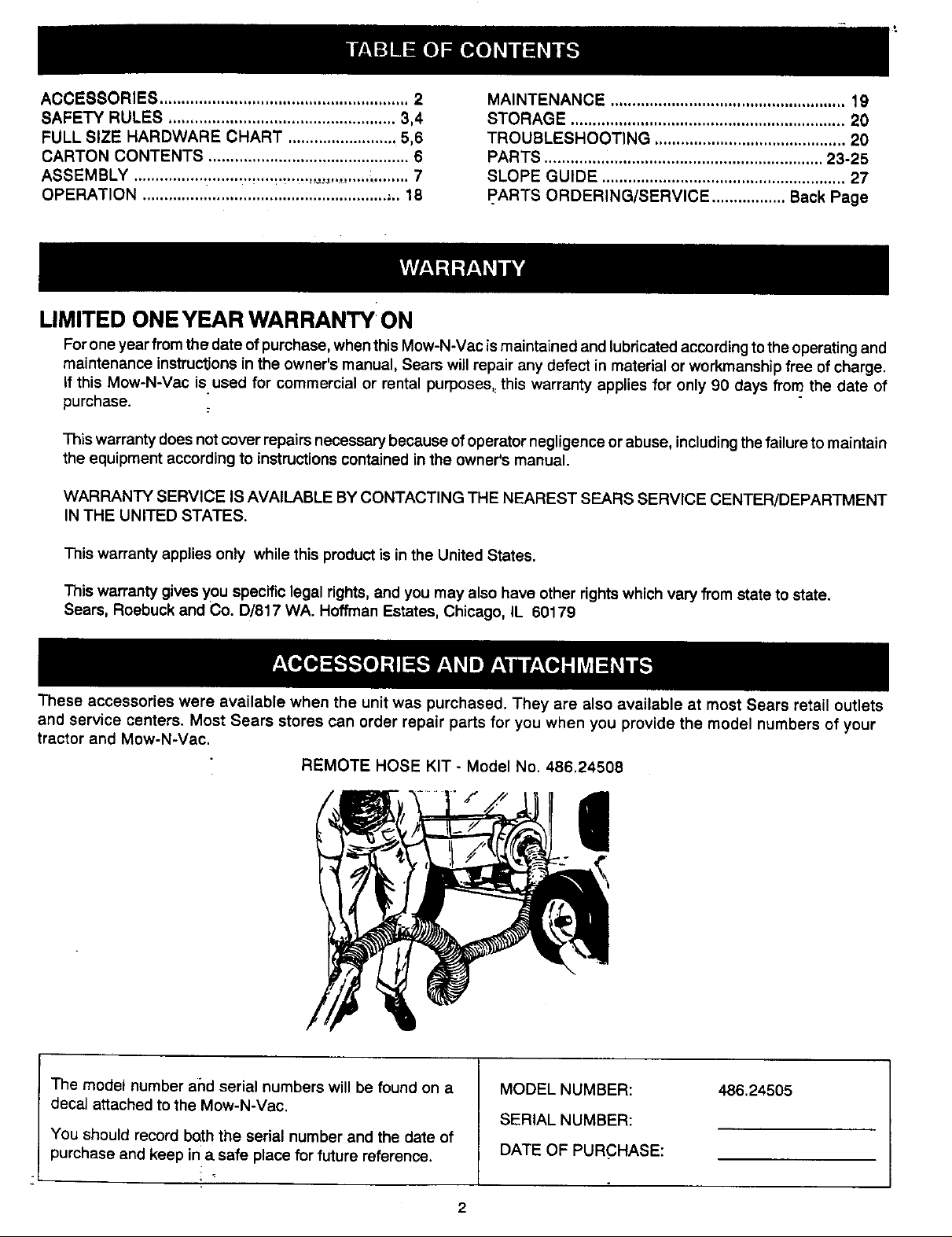
These accessories were available when the unit was purchased. They are also available at most Sears retail outlets
and service centers, Most Sears stores can order repair parts for you when you provide the model numbers of your
tractor and Mow-N-Vac.
REMOTE HOSE KIT - Model No. 486.24508
|
The model number and serial numbers will be found on a
decal attached to the Mow-N-Vac.
You should record bnth the serial number and the date of
purchase and keep in a safe place for future reference.
MODEL NUMBER:
SERIAL NUMBER:
DATE OF PURCHASE:
486.24505
Any power equ pment car_ cause injury if Operated improper y or f the user does not understand how to operate
the equipment. Exercise caution at all times, when using power equipment.
• Read and follow all instructions in this operating and
service instruction manual carefully. Be thoroughly
familiar with the controls and proper use of this power
vacuum. Failure to comply with the instructions in this
manual may result in personal injury.
• Read the vehicle owners manual and vehicle safe
operation rules before using this equipment.
• Never allow children under 16 to operate this Mow-N-
Vac. Children 16 years and older should only operate
under close parental supervision.
• Do not allow anyone to operate this equipment without
proper instructions.
• Do not allow passengers to ride on this equipment or on
the towing vehicle-.
• Keep the area of operation clear of all persons, particu-
larly small children. Also keep area clear of pets,
• Check fuel before starting engine. Do not fill fuel tank
indoors, or when engine is running, or while engine is
hot. Wipe off any spilled fuel before starting engine.
Engine and muffler get hot. Do not touch! To avoid fire
hazard, keep clean of debris and other accumulations,
Never store Mow-N-Vac with fuel in tank. Allow engine to
cool before storing in any enclosure,
Do not change engine governor settings.
Do not operate engine if air cleaner or cover is removed,
except for adjustment. Removal of these parts could
create a fire hazard.
Before cleaning, repairing or inspecting, make certain all
moving parts come to a complete stop. Disconnect spark
plug wire and keep wire away from plug to prevent
accidental starting. Keep throttle control lever in stop
position.
If the Mow-N-Vac should become blocked with debris at
any point, shut engine off and wait until the impeller
comes to a complete stop before attempting to remove
the obstruction. Disconnect spark plug wire to prevent
accidental starting.
If you strike a foreign object, or if your Mow-N-Vac
should start to vibrate abnormally, stop the engine
immediately, disconnect the spark plug wire and move
the wire away from the spark plug. Allow the machine to
stop and take the following steps.
a. Inspect for damage.
b. Repair or replace anydamaged parts.
c. Check for loose partsand tightento assure
continuedsafe operation.
• Check all bolts for tightness at frequent intervals to help
insure safe operation.
• Check vinyl hard top boot frequently for wear. Replace if
worn or damaged.
• Never operate Mow-N-Vac unless deck adapter, hose,
hose adapter (nozzle), elbow, boot and top cover are
properly attached in their place.
• Do not remove top cover or attempt to empty contents of
cart while engine is running.
• Keep hands, feet, face, long hair and clothing out of
Mow-N-Vac inlet and discharge areas. There are
ROTATING BLADES inside these openings.
• Never attempt to change hose adapter (nozzle) or to
: install remote hose attachment when engine is running.
• Keep shields and guards (e.g. hose adapter [nozzle] and
elbow) in place and securely attached.
• Always wear safety glasses or other suitable eye
protection when operating or maintaining this equipment.
• Do not stand behind cart in exhaust discharge area while
engine is running.
• Do not operate this equipment while intoxicated or while
taking drugs or medication that impairs the senses and
reactions.
• When using this equipment, start with the vehicle
transmission in first (low) gear and then gradually
increase speed only as conditions permit.
• Operate this equipment at reduced speed on rough
terrain, along creeks and ditches and on slopes to
prevent tipping or loss of control. Do not drive too close
to a creek or ditch.
Vehicle braking and stability are affected by the addition
of this equipment. Do not fill the Mow-N-Vac to its full
capacity without checking the capability of the towing
vehicle to safely pull and stop with the Mow-N-Vac
attached.
Before operating on any grade (hill) refer to the safety
rules in the vehicle owner's manual concerning safe
operation on slopes. Also refer to the SLOPE GUIDE_n
page 27 of this owner's manual. Do not operate on
slopes in excess of 10 degrees. STAY OFF STEEP
SLOPES.
• Follow the maintenance instructions as outlined in this
manual.
,_ Look for this symbol to point out important safety precautions, it mean--Attentlont!
Become alert!! Your safety is involved.
This Mow-N-Vae was built to be operated according to the rulea for safe operation In this
DANGER: operator can result In serious Injury. This unit is capable of amputating fingers and hands
manual. As with any type of power equipment, carelessness or error on the part of the
and throwing objects Fa ure to observe the following safety Instructions could result In
serious injury or death.
3
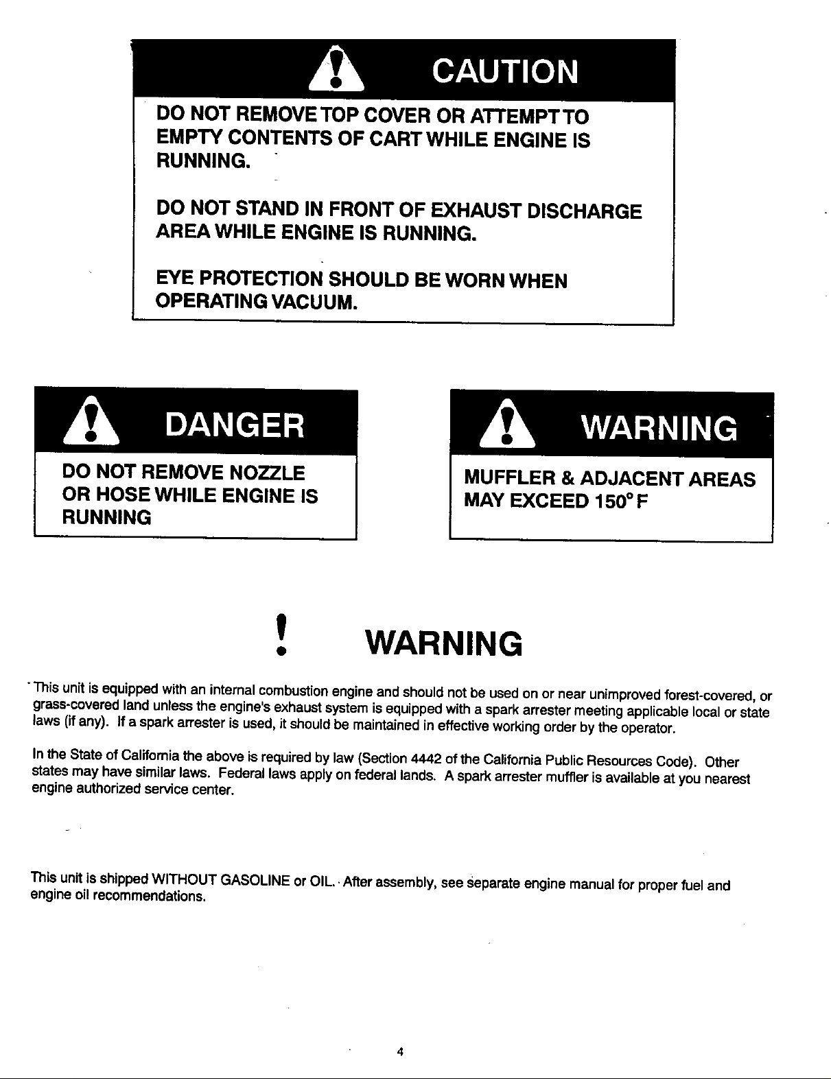
DO NOT REMOVE TOP COVER OR ATTEMPTTO
EMPTY CONTENTS OF CART WHILE ENGINE IS
RUNNING.
DO NOT STAND IN FRONT OF EXHAUST DISCHARGE
AREA WHILE ENGINE IS RUNNING,
EYE PROTECTION SHOULD BE WORN WHEN
OPERATING VACUUM.
DO NOT REMOVE NOZZLE
OR HOSE WHILE ENGINE IS
MUFFLER & ADJACENT AREAS
MAY EXCEED 150 ° F
RUNNING
!
WARNING
This unit is equipped with an internal combustion engine and should not be used on or near unimproved forest-covered, or
grass-covered land unless the engine's exhaust system isequipped with a spark arrester meeting applicable Local or state
laws (ifany). If a spark arrester is used, it should be maintained in effective working order by the operator.
In the State of Califomia the above is required by law (Section 4442 of the California Public Resources Code). Other
states may have similar laws. Federal laws apply on federal lands. A spark arrester muffler is available at you nearest
engine authorized service center.
This unit isshipped WITHOUT GASOLINE or OIL.. After assembly, see Separate engine manual for proper fuel and
engine oil recommendations.
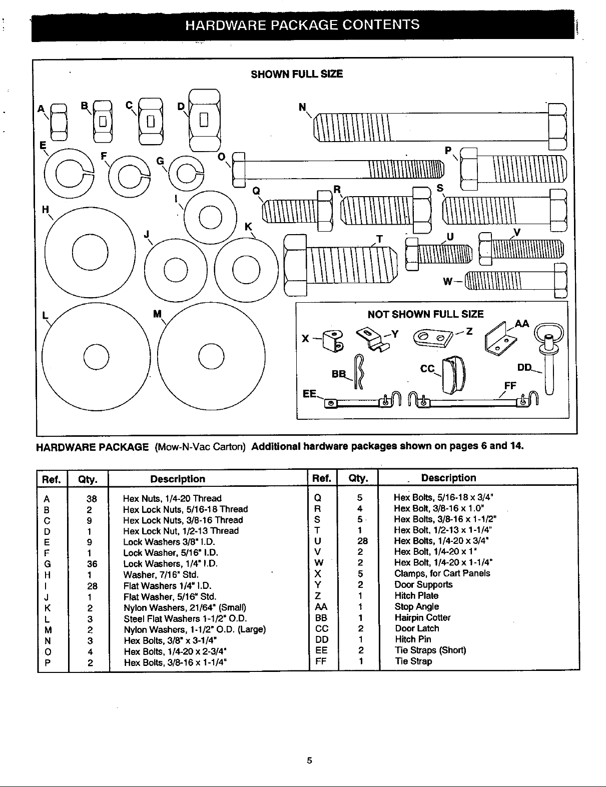
SHOWNFULLSIZE
HARDWARE PACKAGE (Mow-N-Vac Carton) Additional hardware packages shown on pages 6 and 14.
Ref. Qty. Description Ref. Qty.
A 38
B 2
C 9
D 1
E 9
F 1
G 36
H 1
I 28
J 1
K 2
L 3
M 2
N 3
0 4
P 2
Hex Nuts, 1/4.20 Thread Q 5
Hex Lock Nuts, 5/16-18 Thread R 4
Hex Lock Nuts, 3/8-16 Thread S 5
Hex Lock Nut, 1/2-13 Thread T 1
Lock Washers 3/8" I.D. U 28
Lock Washer, 5/16" I.D. V 2
Lock Washers, 1/4" I.D. W 2
Washer, 7/16" Std. X 5
Flat Washers 1/4" I.D. Y 2
Flat Washer, 5/16" Std. Z 1
Nylon Washers, 21/64" (Small) AA 1
Steel Flat Washers 1-1/2" O.D. BB 1
Nylon Washers, 1-1/2" O.D. (Large) CC 2
Hex Bolts, 3/8" x 3-1/4" DD 1
Hex Bolts, 1/4-20 x 2-3/4" EE 2
Hex Bolts, 3/8-16 x 1-1/4" FF 1
Description
Hex Bolts, 5/16-18 x 3/4"
Hex Bolt, 3/8-16 x 1.0"
Hex Bolts, 3/8-16 x 1-1/2"
Hex Bolt, 1/2-13 x 1-1/4"
Hex Bolts, 1/4-20 x 3/4"
Hex Bolt, 1/4-20 x 1"
Hex Bolt, 1/4-20 x 1-1/4"
Clamps, for Cart Panels
Door Supports
Hitch Plate
Stop Angle
Hairpin Cotter
Door Latch
Hitch Pin
Tie Straps (Short)
Tie Strap
5
•SHOWN FULI;;SI;[IE _
.IB ,_._. e Not Shown Full Size
G
I
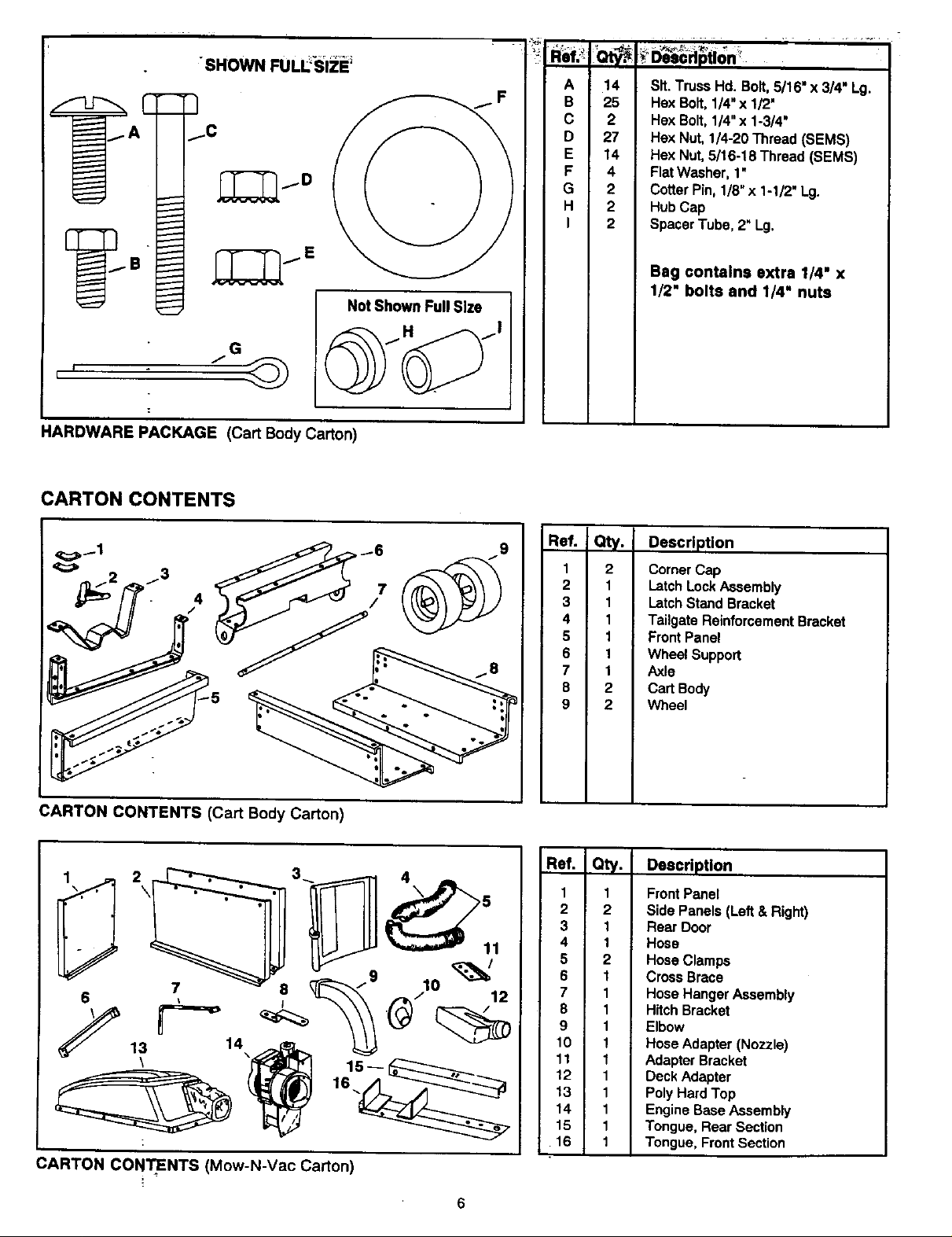
HARDWARE PACKAGE (Cart Body Carton)
CARTON CONTENTS
_t_, • ,_,f ,_
A
B
C
D
E
F
G
H
I
_ Description'
14
Sit. TrussHd. Bolt,5/16" x 3/4" Lg.
25
27
2
14
4
2
2
2
HexBolt,1/4"x 1/2"
Hox Bolt,1/4"x 1-3/4"
HexNut, 1/4-20Thread(SEMS)
HexNut,5/16-18 Thread(SEMS)
FlatWasher, 1"
CotterPin, 1/8"x 1-1/2' Lg.
HubCap
SpacerTube,2" Lg.
Bag contains extra 1/4" x
1/2" bolts and 1/4" nuts
H
CARTON CONTENTS (Cart Body Carton)
_/9 _0 _/1
_ 13 14\_ 15_ i_
(_ARTON CONTENTS (Mow-N-Vac Carton)
Ref. Qty. Description
1
2
2
3
4
5
6
7
8
9
Corner Cap
1
Latoh Lock Assembly
1
Latch Stand Bracket
1
Tailgate Reinforcement Bracket
1
Front Panel
1
Wheel Support
1
Axle
2
Cart Body
2
Wheel
Ref. Qty. Description
1
1 Front Panel
2
2 Side Panels (Left & Right)
3
1 Rear Door
4
1 Hose
5
2 Hose Clamps
6
1 Cross Brace
7
1 Hose Hanger Assembly
8
1 Hitch Bracket
9
1 Elbow
10
1 Hose Adapter (Nozzle)
11
1 Adapter Bracket
12
1 Deck Adapter
13
1 Poly Hard Top
14
1 Engine Base Assemb|y
15
16
1 Tongue, Rear Section
1 Tongue, Front Section
6
This unit is shipped WITHOUT GASOLINE or OIL. -After
assembly, see separate engine manual for proper fuel
and engine oil recommendations.
TOOLS REQUIRED FOR ASSEMBLY
(1) Screwdriver
(1) Pliers
(2) 7/16" Wrenches
(2) 1/2" Wrench
(2) 9/16" Wrenches
(2) 3/4" Wrenches (only if figure 24 on page 14 is used)
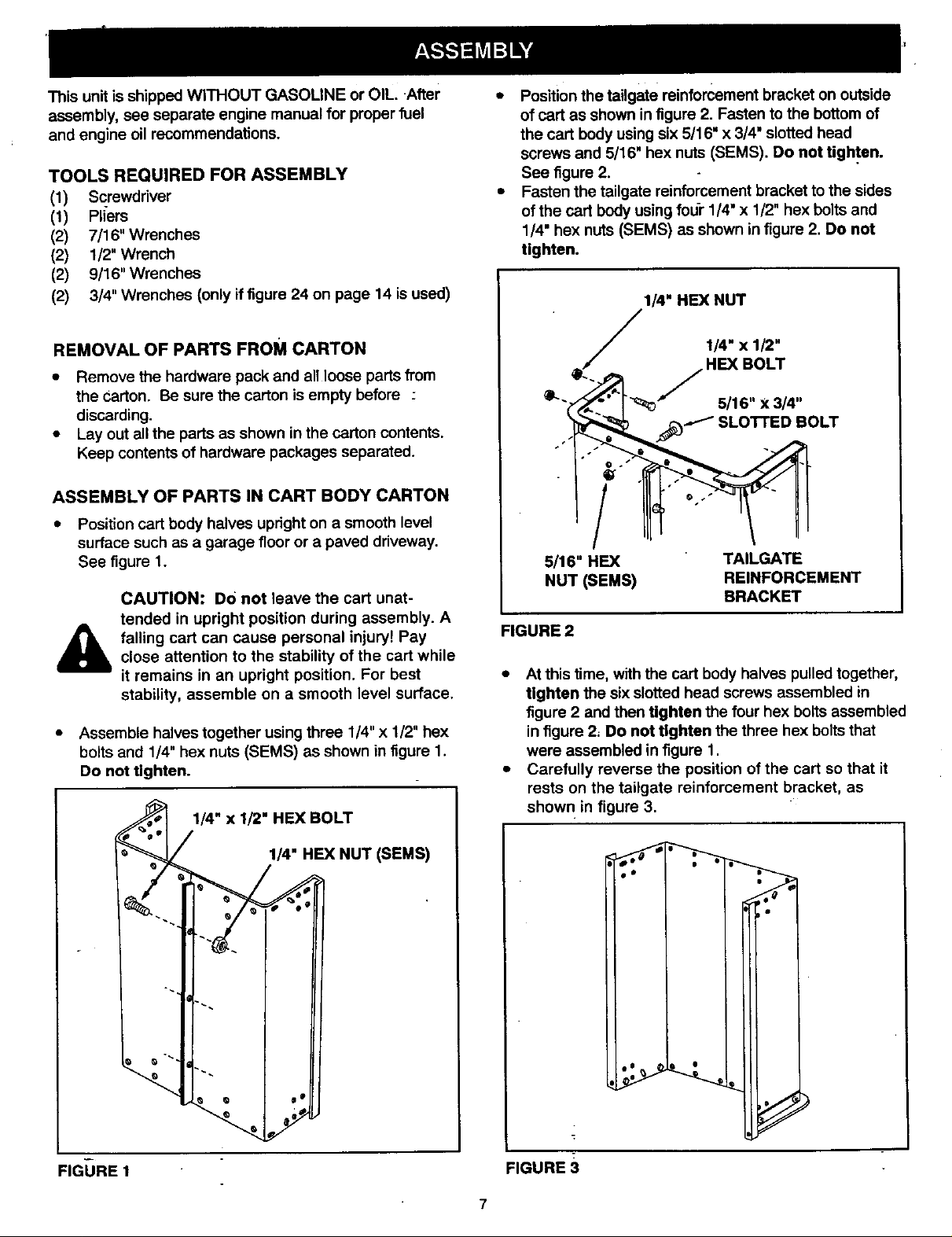
• Position the tailgate reinforcement bracket on outside
of cart as shown in figure 2. Fasten to the bottom of
the cart body using six 5/16" x 3/4" slotted head
screws and 5/16" hex nuts (SEMS). Do not tighten.
See figure 2.
• Fasten the tailgate reinforcement bracket to the sides
of the cart body using four 1/4" x 1/2" hex bolts and
1/4" hex nuts (SEMS) as shown in figure 2. Do not
tighten.
1/4" HEX NUT
REMOVAL OF PARTS FROM CARTON
• Remove the hardware pack and all loose parts from
the Carton. Be sure the carton is empty before :
discarding.
• Lay out all the parts as shown in the carton contents.
Keep contents of hardware packages separated.
ASSEMBLY OF PARTS IN CART BODY CARTON
• Position cart body halves upright on a smooth level
surface such as a garage floor or a paved driveway.
See figure 1.
CAUTION: Do not leave the cart unat-
tended in upright position during assembly. A
falling cart can cause personal injury! Pay
&
• Assemble halves together using three 1/4" x 1/2" hex
close attention to the stability of the cart while
it remains in an upright position. For best
stability, assemble on a smooth level surface.
bolts and 1/4" hex nuts (SEMS) as shown in figure 1.
Do not tighten.
1/4" x 1/2" HEX BOLT
_.J 114"x 1/2"
_'" _;:;__'"I-"_ 5/16 X 3/4"
._ SLOTTED BOLT
5/16" HEX TAILGATE
NUT (SEMS) REINFORCEMENT
BRACKET
FIGURE 2
• At this fime, with the cart body halves pulled together,
tighten the six slotted head screws assembled in
figure 2 and then tighten the four hex bolts assembled
in figure 2, Do not tighten the three hex bolts that
were assembled in figure 1.
• Carefully reverse the position of the cart so that it
rests on the tailgate reinforcement bracket, as
shown in figure 3.
FIGURE 1
1/4" HEX NUT (SEMS)
FIGURE 3
7
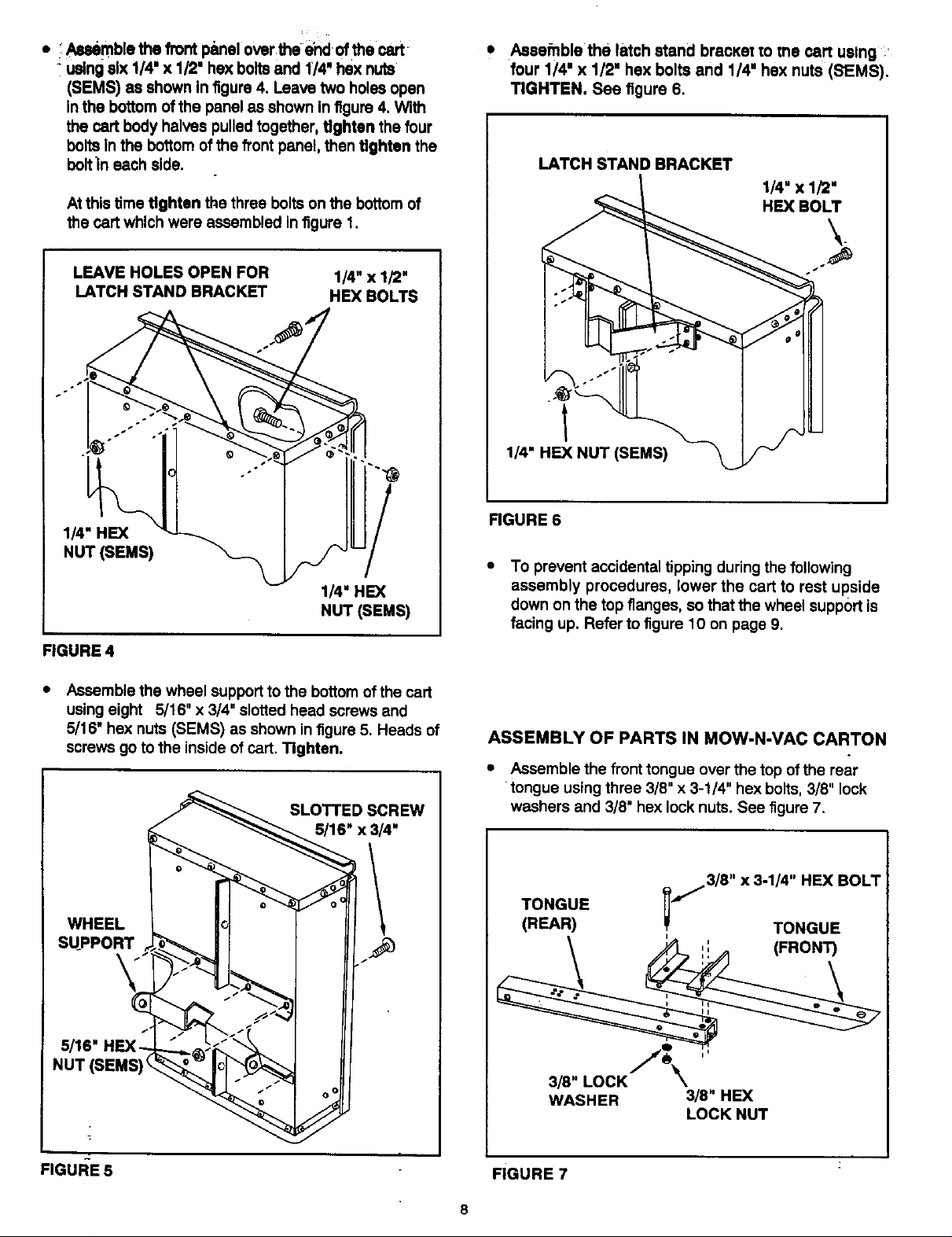
• Autimble the front p_melover the end of the cart
using six 1/4" x 1/2' hex bolts and 1/4" hex nuts
(SEMS) as shown in figure 4. Leave two holes open
in the bottom of the panel as shown in figure 4. With
the cart body halves pulled together, tighten the four
bolts In the bottom of the front panel, then tighten the
boltln each side.
At this time tighten the three bolts on the bottom of
the cart which were assembled infigure 1.
• Assefnble the latch stand braCKet to tne cart uslng
four I/4' x I/2" hex bolts and I/4" hex nuts (SEMS).
TIGHTEN. See figure 6.
LATCH STANDBRACKET
1/4" x 1/2'
HEX BOLT
LEAVE HOLES OPEN FOR
LATCH STAND BRACKET
114"HEX
NUT (SEMS)
1/4" x 1/2"
HEX BOLTS
/
I
/
1/4" HEX
NUT (SEMS)
FIGURE 4
Assemble the wheel support to the bottomof the cart
using eight 5/16" x 3/4" slotted head screws and
5/16" hex nuts (SEMS) as shown infigure 5. Heads of
screws go to the inside of cart. Tighten.
SLO'I-rED SCREW
5/16" x 3/4"
1/4" HEX NUT (SEMS)
FIGURE6
To prevent accidental tipping during the following
assembly procedures, lower the cart to rest upside
down on the top flanges, so that the wheel support is
facing up. Refer to figure 10 on page 9.
ASSEMBLY OF PARTS IN MOW-N-VAC CARTON
• Assemble the fronttongue over the top ofthe rear
•tongue using three 3/8" x 3-1/4" hex bolts, 3/8" lock
washers and 3/8" hex lock nuts. See figure 7.
WHEEL
SUPPORT
NUT(SEMS
FIGUI_E 5
_j.13/8" X 3-1/4" HEX BOLT
l
TONGUE
(REAR) _ TONGUE
\
3/8" LOCK _
WASHER 3/8" HEX
FIGURE 7
8
LOCK NUT
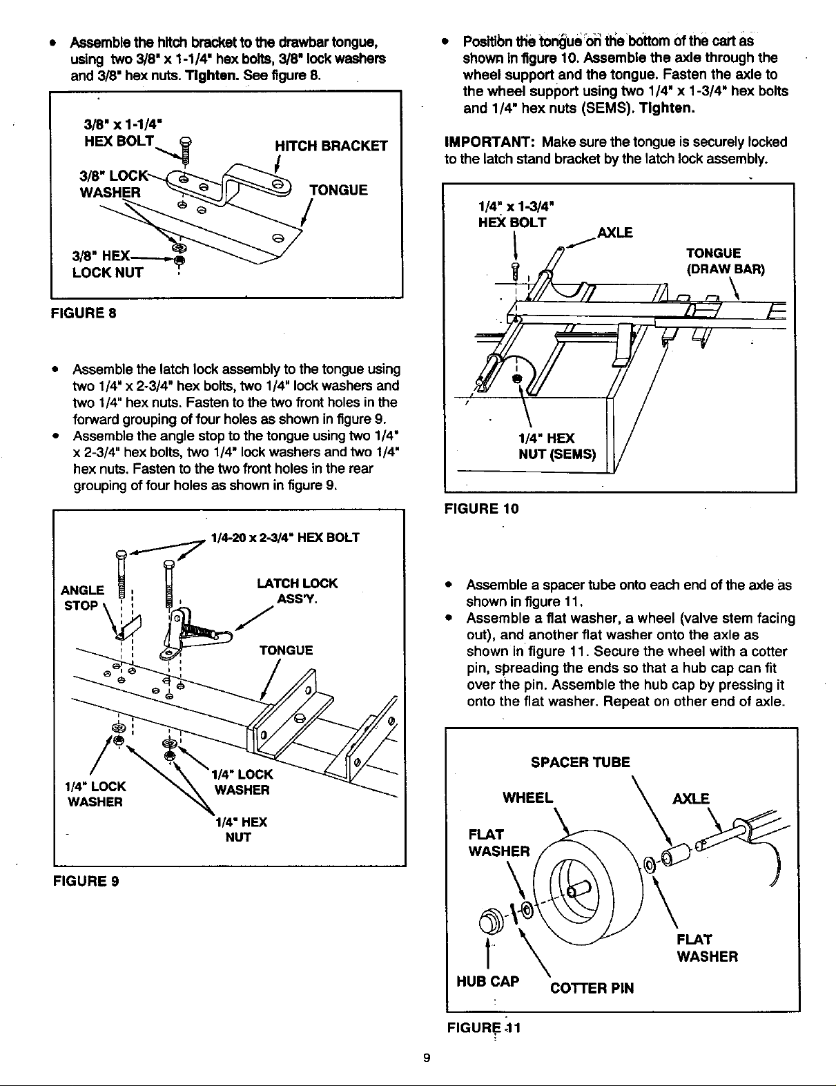
• Assemble the hitch bracket to the drawbar tongue,
using two 3/8" x 1-1/4" hex bolts, 3/8" lock washers
and 3/8" hax nuts. Tighten. See figure 8.
3/8" x 1-1/4"
HEX BOLT _ HITCH BRACKET
3/8" LOC K'_(__F--_
WASHER _ ]lJ_ TONGUE
3/8" HEX._,,._
LOCK NUT
FIGURE 8
• Assemble the latch lock assembly to the tongue using
two 1/4" x 2-3/4" hex bolts, two 1/4" lock washers and
two 1/4" hex nuts. Fasten to the two front holes in the
forward grouping of four holes as shown in figure 9.
• Assemble the angle stop to the tongue using two 1/4"
x 2-3/4" hex bolts, two 1/4" lock washers and two 1/4"
hex nuts. Fasten to the two front holes in the rear
grouping of four holes as shown in figure 9.
Positibn the tongue 0_ _e bottom of the cart as
shown in figure 10. Assemble the axle through the
wheel supportand the tongue. Fasten the axle to
the wheel support using two 1/4" x 1-3/4" hex bolts
and 1/4" hex nuts (SEMS). Tighten.
IMPORTANT: Make sure the tongue issecurely locked
to the latch stand bracket by the latch lockassembly.
1/4" x 1-3/4"
HEX BOLT
..,..I AXLE
/_ TONGUE
_ , _ (DRAW BAR)
/1
"( ) /
FIGURE 10
114-20 x 2-3/4" HEX BOLT
ANGLE LATCH LOCK
ASS'Y.
_,' TONGUE
1/4" LOCK
WASHER
1/4" HEX
NUT
FIGURE 9
Assemble a spacer tube onto each end of the axle as
shown in figure 11.
Assemble a fiat washer, a wheel (valve stem facing
out), and another flat washer onto the axle as
shown in figure 11. Secure the wheel with a cotter
pin, spreading the ends so that a hub cap can fit
over the pin. Assemble the hub cap by pressing it
onto the flat washer. Repeat on other end of axle.
SPACER TUBE
WHEEL
FLAT
AXLE
WASHER
FLAT
.
HUB CAP
co'rrER PIN
WASHER
FIGURE _11
 Loading...