

Page 1
®
Safety
Assembly
Operation
Maintenance
Parts
STOP
DO NOT RETURN TO STORE
For Missing Parts or Assembly
Questions Call 1-866-576-8388
Most fasteners are readily available
through any hardware store
Page 2
TABLE OF CONTENTS
MODEL NUMBER: 486.244283
SERIAL NUMBER: __________________
DATE OF PURCHASE: __________________
..................................
..................................................
..................
.............................................................
..............................................................
....................................................
SAFETY
Page 3
WARRANTY
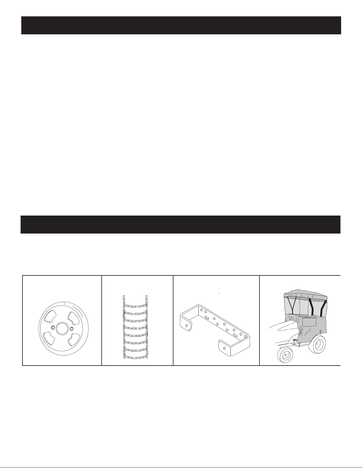
ACCESSORIES AND ATTACHMENTS
Page 4
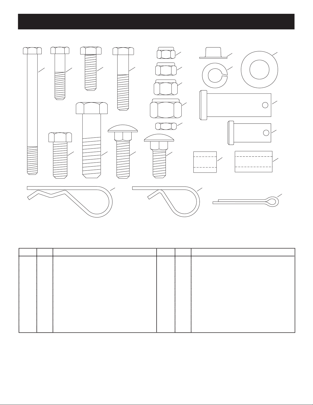
HARDWARE PACKAGE CONTENTS
A 1 Hex Bolt, 1/4" x 3-1/4" LG.
B 1 Hex Bolt 1/4" x 1-1/4"
C 4 Hex Bolt, 5/16" x 1"
D 1 Hex Bolt, 5/16" x 1-1/2"
E 2 Hex Bolt, 3/8" x 1"
F 1 Hex Bolt, 1/2" x 1-3/4"
G 4 Carriage Bolt 3/8" x 1-1/4"
H 18 Carriage Bolt, 3/8" x 1"
I 3 Nylock Nut, 1/4"
J 5 Nylock Nut, 5/16"
K 22 Nylock Nut, 3/8"
L 1 Nylock Nut, 1/2"
M 4 Hex Jam Nut, 5/16"
N 2 Palnut, 3/8"
O 2 Lock Washer, 3/8"
P 3 Washer 1/2"
Q 1 Clevis Pin, 5/8" x 1-3/4"
R 2 Clevis Pin, 1/2" x 1"
S 1 Spacer, 5/8" LG.
T 2 Spacer, 1" LG.
U 3 Hairpin Cotter, Large
V 4 Hairpin Cotter, Small
W 2 Cotter Pin 1/8" x 1-1/4"
K
M
J
I
A B
S
T
Q
D
P
U
V
W
N
C
R
E F G
H
L
O
Page 5
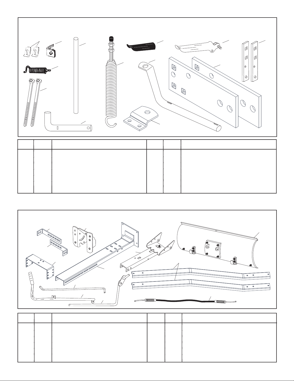
REF. QTY. DESCRIPTION
1 1 Long Hanger Bracket
2 1 Short Hanger Bracket
3 1 Rear Mounting Bracket
4 1 Pivot Support Bracket
5 1 Thrust Channel
6 1 Channel Assembly
REF. QTY. DESCRIPTION
AA 2 Cable End Fitting
BB 1 Cable Mount Bracket
CC 1 Angle Lock Spring
DD 2 Nylon Tie
EE 1 Spring Mount Rod
FF 1 Channel Pivot Pin
7 1 Blade Assembly
8 1 Blade Pivot Rod
9 1 Lift Handle Tube
10 1 Lift Handle Rod
11 2 Rear Support Channel
12 1 Cable
8
12
9
2
1
3
4
6
11
7
5
10
AA
BB
CC
DD
EE
FF
GG
MM
JJ
HH
II
LL
KK
GG 1 Blade Adjust Spring
HH 1 Plastic Grip
II 1 Grip Assembly
JJ 2 Angle Lock Bar
KK 1 Blade Pivot Shaft
LL 2 Frame Bracket
MM 1 Rear Locating Bracket
Page 6
Remove the loose parts and the hardware packages
Do not
begin assembling
Allow engine, muffl er and exhaust defl ector to cool
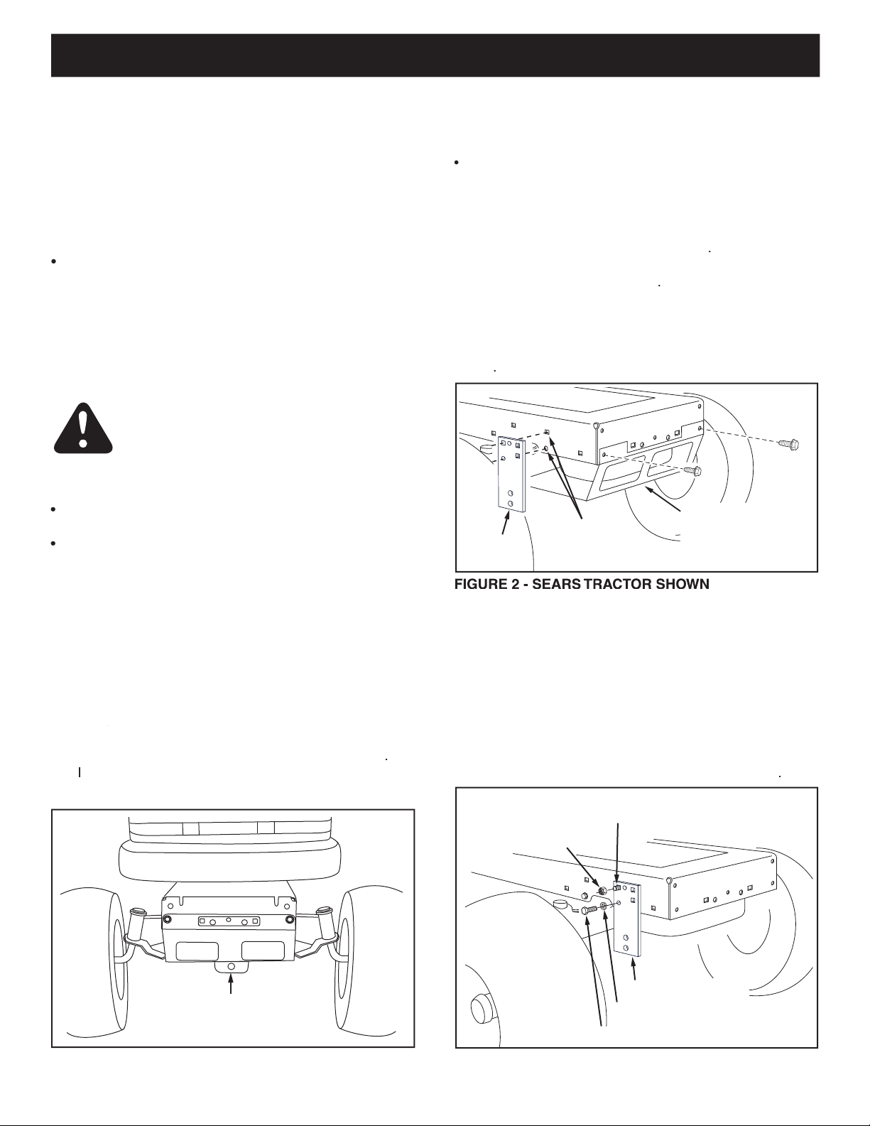
Right hand (R.H.) and left hand (L.H.) are
under the front of your tractor
MOWER DECK
SUSPENSION
BRACKET
3/8" LOCK WASHER (O)
3/8" X 1" HEX BOLT (E)
FRAME BRACKET
3/8" NYLON
LOCK NUT (K)
3/8" X 1"
CARRIAGE BOLT (H)
REMOVE BROWNING
SHIELD ON SEARS
TRACTORS
MOUNTING
HOLES ON
SEARS TRACTORS
a frame bracket to each sid
the bro
of
the front axle and
the browning shield in
OPERATION
Page 7

3/8" x 1-1/4"
CARRIAGE BOLT (G)
3/8" NYLOCK NUT (K)
HANGER BRACKETS
Ends down when "H" is 6" or less
Ends up when "H" is more than 6"
W
L
FRONT PLATE
3/8" x 1-1/4"
CARRIAGE BOLT (G)
3/8" NYLOCK NUT (K)
LONG HANGER
BRACKET
12-1/4"
SHORT HANGER
BRACKET
If you have a
Skip to step 9 on page 10.
JOHN DEERE LT TRACTOR
W
L
H
Measure the inside distance between the Frame
Select the set of slots in the top of the Thrust Channel
in step 5.
measured in step 5
measured
Proceed to step 9 on page 10.
Page 8

W
SEARS (LT) TRACTOR FRAME
H
SUSPENSION
BRACKET
G
R
O
U
N
D
L
Select a set of slots in the top of the Thrust Channel
in step 7.
measured in step 7
Proceed to step 9 on page 10.
3/8" x 1-1/4"
CARRIAGE BOLT (G)
3/8" NYLOCK NUT (K)
HANGER BRACKETS
Ends down when "H" is 6" or less
Ends up when "H" is more than 6"
W
L
FRONT PLATE
Locate the Mower Deck Suspension Brackets on each
Measure the height above the ground of the deck
Measure the inside distance between the Mower
Page 9

SEARS LAWN
TRACTORS
TRACTOR
SUSPENSION
BRACKET
LOCATE HANGER BRACKETS IN
MIDDLE SET OF SLOTS IN THRUST CHANNEL
9.75"
SEARS GARDEN
TRACTORS
12"
TRACTOR
SUSPENSION
BRACKET
LOCATE HANGER BRACKETS IN
MIDDLE SET OF SLOTS IN THRUST CHANNEL
MTD - LAWN TRACTORS
WITH FAST ATTACH FEATURE
13"
TRACTOR
SUSPENSION
BRACKET
LOCATE HANGER BRACKETS IN FRONT
SET OF SLOTS IN THRUST CHANNEL
MTD - GARDEN TRACTORS
WITH FAST ATTACH FEATURE
13"
TRACTOR
SUSPENSION
BRACKET
LOCATE HANGER BRACKETS IN FRONT
SET OF SLOTS IN THRUST CHANNEL
MTD GARDEN
TRACTORS
13"
TRACTOR
SUSPENSION
BRACKET
LOCATE HANGER BRACKETS IN FRONT
SET OF SLOTS IN THRUST CHANNEL
MTD LAWN
TRACTORS
13"
FRAME
BRACKET
LOCATE HANGER BRACKETS IN FRONT
SET OF SLOTS IN THRUST CHANNEL
5/16" x 1"
HEX BOLT
MURRAY TRACTORS
8.5"
TRACTOR
SUSPENSION
BRACKET
LOCATE HANGER BRACKETS IN REAR
SET OF SLOTS IN THRUST CHANNEL
FORWARD SLOTS MAY BE USED ON
SOME MURRAY TRACTORS
JOHN DEERE SABRE
13"
FRAME
BRACKET
3/8" x 1"
CARRIAGE
BOLT
LOCATE HANGER BRACKETS IN FRONT
SET OF SLOTS IN THRUST CHANNEL
12.75"
3/8" x 1"
HEX BOLT
3/8" x 1"
CARRIAGE
BOLT
LOCATE HANGER BRACKETS IN
MIDDLE SET OF SLOTS IN THRUST CHANNEL
FRAME
BRACKET
SEARS TRACTORS WITH
CENTER SUSPENSION BRACKET
JOHN DEERE LT
13"
FRAME
BRACKET
LOCATE HANGER BRACKETS IN FRONT
SET OF SLOTS IN THRUST CHANNEL
5/16" x 1"
HEX BOLT
Page 10

Place the rear of the Thrust Channel between the
If the Rear Support Channels bump against bottom
Tighten
all bolts and nuts installed up to this point.
Assemble the pivot support bracket to the front of the
tighten.
REAR SUPPORT
CHANNELS
REAR MOUNTING
BRACKET
REAR LOCATING
BRACKET
3/8" X 1"
CARRIAGE BOLT (H)
3/8" NYLOCK NUT (K)
TRACTOR
DRAWBAR
5/8" X 1-3/4"
CLEVIS PIN (Q)
LARGE
HAIRPIN
COTTER (U)
REAR MOUNTING
BRACKET
REAR LOCATING
BRACKET
REAR SUPPORT
CHANNEL
Slide the Rear Support Channels under the rear of
REAR
SUPPORT
CHANNEL
FRONT
PLATE
3/8" X 1"
CARRIAGE BOLT (H)
3/8" NYLOCK
NUT (K)
4" to 5"
GROUND
1/2"X 1" CLEVIS PIN (R)
1/2" WASHER (P)
Slide the Thrust Channel under the front of the tractor.
Install the Rear Locating Bracket to the top of the
nuts.
Install the Rear Support Channels to the middle set of
3/8" X 1"
CARRIAGE BOLT (H)
3/8" NYLOCK
NUT (K)
Page 11

Assemble a 3/8" x 1-1/4" carriage bolt (G) through the
Tighten.
Use a hammer to tap a 3/8" palnut (N) onto one
Assemble one 5/16" jam nut (M) approximately 3/4"
Some adjustment of jam nuts may be required
3/8" PALNUT (N)
PIVOT
PLATE
SPRING
MOUNT
ROD
3/8" PALNUT (N)
CHANNEL ASSEMBLY
5/16" JAM NUT (M)
5/16" JAM NUT (M)
CABLE MOUNT
BRACKET
REAR
3/4"
Place the two angle lock bars together so that all holes
Finger tighten only.
Insert the round hook end of the angle lock spring up
Insert the angle lock bars down through the slot in the
so that lock bars can pivot freely.
At this time
tighten
the 3/8" carriage bolt and nylon
When the angle lock bars are pulled back, the
1/4" x 3-1/4"
HEX BOLT (A)
1" SPACERS (T)
1/4" NYLOCK
NUT (I)
ANGLE
LOCK
SPRING
(A)
3/8"x 1-1/4"
CARRIAGE BOLT (G)
CHANNEL
ANGLE
LOCK BARS
3/8" NYLOCK
NUT (K)
3/8" x 1-1/4"
CARRIAGE BOLT (G)
3/8" NYLOCK
NUT (K)
ALIGN CABLE
MOUNT BRACKET
WITH L.H. HOLE
ANGLE
LOCK
BARS
FRONT
Page 12

Assemble ball end of control cable up through hole in
Tighten.
Make sure the cable mount bracket is aligned
To attach the blade to the channel assembly, align the
Remove the plastic cap and one 3/8" hex nut from the
Assemble the 1/2" washer (P) onto the channel pivot
Attach the channel assembly to the tractor by placing
in the
3/8" HEX NUT
(TOP)
PLASTIC
CAP
3/8" HEX NUT
(BOTTOM)
BLADE
1/8" x 1-1/4"
COTTER PIN (W)
BLADE
PIVOT
SHAFT
SPRING
MOUNT
ROD
BLADE
ADJUST
SPRING
1/8" x 1-1/4"
COTTER
PIN (W)
PIVOT PLATE
1/4" x 1-1/4"
HEX BOLT (B)
CABLE END
FITTING
1/4" NYLON LOCK NUT (I)
5/8" SPACER (S)
CHANNEL
ASSEMBLY
HOLE
REAR
1/2" WASHER (P)
CHANNEL
PIVOT PIN
CHANNEL
ASSEMBLY
HOLE IN END OF
CHANNEL ASSEMBLY
SMALL HAIRPIN
COTTER (V)
PIVOT SUPPORT
BRACKET
Page 13

From the left side, insert the welded end of the lift
Using the furnished grease packet, apply a light
Place the long end of the blade pivot rod down
Use the two plastic ties to hold the cable securely
Screw one 5/16" jam nut (M) approximately 3/4" onto
Some adjustment of jam nuts may be required
HANDLE
GRIP
BALL
END
CABLE MOUNT BRACKET
5/16" JAM NUTS (M)
5/16" x 1-1/2"
HEX BOLT (D)
PLASTIC
GRIP
LOCK RELEASE
GRIP ASSEMBLY
1/4" WELD
BOLT
CABLE END
FITTING
5/16" NYLOCK
NUT (J)
1/4 " NYLOCK
NUT (I)
CABLE
LIFT HANDLE ROD
SMALL HAIRPIN COTTER (V)
LONG PIN
(LIFT LINK)
WELDED BRACKET
LIFT HANDLE TUBE
BLADE
PIVOT
ROD
LIFT HANDLE
TUBE
SMALL HAIRPIN
COTTER (V)
SMALL HAIRPIN COTTER (V)
PLASTIC TIES
BLADE PIVOT SHAFT
Attach the lock release grip assembly to the lift handle
Assemble the ball end of the cable to a cable end
Page 14

Use the handle grip located on the end of the handle
OPERATION
Raise the blade to transport position. To unlock
BLADE SHOE
BLADE PIVOT SHAFT
LIFT HANDLE TUBE
BLADE PIVOT ROD
BLADE
ADJUST
SPRING
ANGLE
LOCK
BARS
LOCK RELEASE GRIP ASSEMBLY
CONTROL CABLE
LIFT HANDLE ROD
HANDLE TUBE
PULL BACK AND
LIFT UP TO
LOWER BLADE
PULL BACK AND
PUSH DOWN TO
RAISE BLADE
HANDLE GRIP
HANDLE TUBE
LOCK RELEASE
GRIP ASSEMBLY
LIFT ROD
Page 15

Prepare the lawn tractor engine for cold weather using
Always begin with the transmission in fi rst (low) gear
repeatedly push snow in the same direction,
To reduce icing on the blade, allow the lawn tractor
For improved snow removal performance, coat the blade
MAINTENANCE SCHEDULE
complete regular service.
After each use
Read and follow the maintenance schedule and the
Every season
Before storage
Check for worn or damaged parts X
Clean Blade X X
Lubricate Blade X
MAINTENANCE
GREASE
LUBRICATE
LUBRICATE
Page 16

The tension of the blade adjust spring may be altered
The blade shoes at the ends of blade may be raised
SERVICE AND ADJUSTMENTS
If the blade will not unlock and pivot, the angle lock
When the snow blade is not being used, remove all
Touch up bare metal with paint or apply a light coat of
Lubricate all pivot points and all points shown in fi gure
Store in a dry area, protected from weather.
Lower the blade head to the ground with the blade in
Remove the clevis pin that fastens the blade's rear
Remove the frame brackets (if used). See fi gure 3 on
Back the tractor off of the blade assembly.
CABLE MOUNT BRACKET
5/16" HEX
JAM NUT
CONTROL
CABLE
5/16" HEX
JAM NUT
BLADE SHOE
STORAGE
TROUBLESHOOTING
Page 17

Page 18

PARTS
44
6
59
28
48
59
52
61
29
55
58
51
61
55
58
B
B
A
A
3
8
8
10
30
35
35
50
33
34
45
38
23
46
32
42
56
15
14
19
39
40
24
27
20
48
48
37
47
41
41
25
36
25
25
41
41
11
36
21
21
17
13
6
47
43
12
26
4
5
4
4
7
7
6
6
6
6
47
31
55
36
25
C
C
57
54
2
1
22
49
52
52
38
D
D
51
58
52
60
53
51
52
52
18
16
16
52
51
51
51
51
51
9
52
52
52
63
62
64
65
Page 19

34 23856 1 Spring Mount Rod
35 44917 2 Palnut, 3/8"
36 43010 3 Cotter Pin 1/8" x 1-1/4"
37 43348 1 Angle Lock Spring
38 746-0260 2 Cable End Fitting
39 731-0869 1 Grip, Plastic
40 46471 1 Handle, Grip
41 712-0256 4 Hex Jam Nut, 5/16-24 Thread
42 23658 1 Spacer
43 43085 1 Hex Bolt, 5/16-18 x 1-1/2"
44 43063 4 Bolt, Hex 5/16-18 x 1" Lg.
45 05762 1 Cable Mount Bracket
46 1509-90 1 Hex Bolt 1/4-20 x 1-1/4"
47 47189 3 Nylon Lock Nut, 1/4-20 Thread
48 710-0305 4 Carriage Bolt, 3/8-16 x 1-1/4"
49 46065 1 Channel Pivot Pin
50 63034 1 Lift Link Assembly
51 43350 18 Carriage Bolt, 3/8-16 x 1"
52 HA21362 22 Nylon Lock Nut, 3/8-16 Thread
53 HA23380 1 Rear Locating Bracket
54 726-0178 2 Plastic Tie
55 R19171616
56 46071 1 Hex Bolt, 1/4-20 x 3-1/4" Lg. Gr
57 43349 1 1/4" x 1" Spring Pin
58 43343 3 Pin, 3/32" Hairpin (Large)
59 44062 2 Clevis Pin, 1/2" x 1" Lg.
60 HA3980 1 Clevis Pin, 5/8" x 1-3/4" Lg.
61 25124 2 Frame Bracket
62 43003 2 Lock Washer, 3/8"
63 43001 2 Hex Bolt, 3/8-16 x 1"
64 R74780828 1 Hex Bolt, 1/2-13 x 1-3/4"
65 712-3083 1 Nylon Lock Nut, 1/2-13 Thread
49828 1 Owners Manual
REF. PART QTY. DESCRIPTION
NO. NO.
REF. PART QTY. DESCRIPTION
NO. NO.
Page 20

® Registered Trademark / TM Trademark /SM Service Mark of Sears Brands, LLC
® Marca Registrada /
TM
Marca de Fábrica / SM Marca de Servicio de Sears Brands, LLC
MC
Marque de commerce / MD Marque déposée de Sears Brands, LLC © Sears Brands, LLC
Get it fixed, at your home or ours!
Your Home
For repair – in your home – of all major brand appliances,
lawn and garden equipment, or heating and cooling systems,
no matter who made it, no matter who sold it!
For the replacement parts, accessories and
owner’s manuals that you need to do-it-yourself.
For Sears professional installation of home appliances
and items like garage door openers and water heaters.
1-800-4-MY-HOME
®
(1-800-469-4663)
Call anytime, day or night (U.S.A. and Canada)
www.sears.com www.sears.ca
Our Home
For repair of carry-in items like vacuums, lawn equipment,
and electronics, call or go on-line for the location of your nearest
Sears Parts & Repair Center.
1-800-488-1222
Call anytime, day or night (U.S.A. only)
www.sears.com
To purchase a protection agreement (U.S.A.)
or maintenance agreement (Canada) on a product serviced by Sears:
1-800-827-6655 (U.S.A.) 1-800-361-6665 (Canada)
Para pedir servicio de reparación
a domicilio, y para ordenar piezas:
1-888-SU-HOGAR
®
(1-888-784-6427)
Au Canada pour service en français:
1-800-LE-FOYER
MC
(1-800-533-6937)
www.sears.ca
 Loading...