

Craftsman 486244280 Owner’s Manual
,OWNERS
MANUAL
Model No.
486.244280
48"
SNOW BLADE
CRAFTSMAN
CAUTION:
Read Rules for
Safe Operation
and Instructions
Carefully
48" SNOW BLAD
Sears, Roebuck and Co., Hoffman Estates, IL. 60179 U.S.A.
RULES FOR SAFE, OPERATION
Any power equipment can cause injurY if operated im properly or if the user does not understand how to operate the equipment.
LOOK FOR THIS SYMBOL TO POINT OUT
IMPORTANT SAFETY PRECAUTIONS. IT
MEANS--A'FTENTION! BECOMEALERT! YOUR
SAFETY IS INVOLVED.
Exercise caution at all times, when using power equipment.
1. Read the tractor and snow blade owners manuals and know how to operate your tractor before using tractor with snow blade
attachment.
2. Never operate tractor and snow blade without wearing proper clothing suited to weather conditions and operation of
controls.
3. Never allow children to operate tractor and snow blade, and do not allow adults to operate without proper instructions.
4. Always begin with transmission in first (low) gear and gradually increase speed as required.
CONGRATULATIONS on your purchase of a Sears snow
blade, it has been designed, manufactured and engi-
neered to give you the best possible dependability and
performance.
Should you experience any problem you can not easily
remedy, please contact your nearest Sears Service Cen-
ter/Department. We have competedt well trained techni-
cians and the proper tools to service or repair this snow
blade.
Please read and retain this manual. The instructions witl
enable you to assemble and maintain your snow blade
property. Always observe the "SAFETY RULES".
CUSTOMER RESPONSIBILITIES
• Read and observe the safety rules.
• Follow the instructions under ='Customer Responsibili-
•ties" and "Storage" sections of this manual.
LIMITED ONE YEAR WARRANTY ON 48" SNOW BLADE
For one year from the date of purchase, when this snow blade is maintained and lubricated according to the operating and
maintenance instructions in the owner's manual, Sears will repair free of charge any defect in material or workmanship.
If this snow blade is used for corn mercial or rental purposes,this warranty applies for only 90 days from the date of purchase.
This warranty does not cover:
repairs necessary because of operator negligence or abuse, including the failure to maintain the equipment according
to instructions contained in the owner's manual.
WARRANTY SERVlCE IS AVAILABLE BY CONTACTING THE NEAREST SEARS SERVICE CENTER/DEPART
MENT IN THE UNITED STATES.
This warranty applies only while this product is in the United States.
This warranty gives you specific legai rights, and you may also t_ave other rights which vary from state to state.
Sears, Roebuck and Co. D/817 WA. HOFFMAN ESTATES, CHICAGO, ILLINOIS 60179
TABLE OF CONTENTS
SAFETY RULES ............................................................... 2
CUSTOMER RESPONSIBILITIES ............................... 2,15
ACCESSORIES .................................................................. 3
CARTON CONTENTS ................................................... 3-4
ASSEMBLY FOR 917... SERIES .................................. 5-6
ASSEMBLY FOR 502.. SERIES ................................... 7-8
ASSEMBLY FOR 536... SERIES ................................. 9-10
UNtVERSAL FINALASSEMBLY ................................ 11-14
OPERATION AND ADJUSTMENTS .......................... t4-15j
STORAGE ....................................................................... 15:,
PARTS EXPLOSION ....................................................... 16
REPAIR PARTS ......................... ;.................................... 17
PARTS ORDERING/SERVICE .................... BACKCOVER
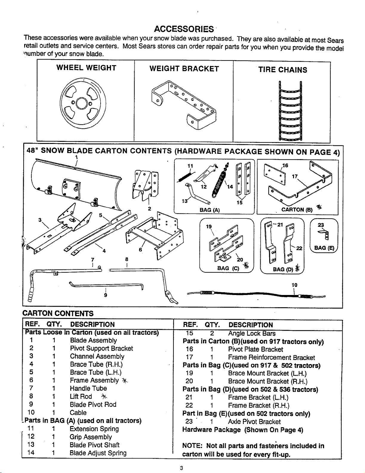
ACCESSORIES
These accessories were available when your snow blade was purchased. They are also avai[abte at mostSears
retail outlets and service centers. Most Sears stores can order repair parts for you when you providethe model
_-_umberof your snow blade.
WHEEL WEIGHT
48" SNOW BLADE CARTON CONTENTS (HARDWARE PACKAGE SHOWN ON PAGE 4)
1
WEIGHT BRACKET
TIRE CHAINS
/
1 15
2
BAG (A)
f
CARTON (B) _t_
23
7 8
1
9
CARTON CONTENTS
REF. QTY. DESCRIPTION
Parts L6ose in Carton (used on all tractOrS)
1
2
3
4
5
6
7
8
9
10
I
Blade Assembly
I
Pivot Support Bracket
I
Channel Assembly
I
Brace Tube (R.H.)
I
Brace Tube (L.H.)
I
Frame Assembly
I
Handle Tube
I
Uft Rod %
I
Blade Pivot Rod
I
Cable
lParts in BAG (A) (used on all tractors)
! 1 1 Extension Spring
12 1 Grip Assembly
13 1 Blade Pivot Shaft
14 1 Blade Adjust Spring
_'_ _21__
_. BAG (C) _J
BAG (D)
10
REF. QTY. DESCRIPTION
15 2 Angle Lock Bars
Parts in Carton (B)(used on 917 tractors only)
! 6 1 Pivot Plate Bracket
17 1 Frame Reinforcement Bracket
Parts in Bag (C)(used on 917 & 502 tractors)
19 1 Brace Mount Bracket (LH.)
20 1 Brace Mount Bracket (R.H.)
Parts in Bag (D)(used on 502 & 536 tractors)
21 1 Frame Bracket (L.H.)
22 1 Frame Bracket (R.H.)
Part in Bag (E)(used on 502 tractors only)
23 1 Axle Pivot Bracket
Hardware Package (Shown On Page 4)
NOTE: Not all parts and fasteners included in
carton will be used for every fit-up.
A--
®@®®. u
- .
x-___ Iit tll
_ _ _ _ _:__b . N !_I1_1
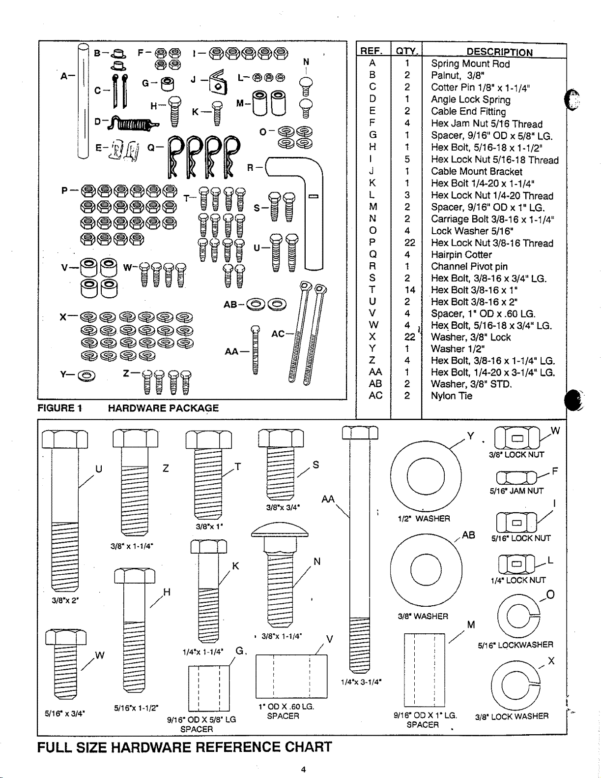
FIGURE Ir HARDWARE PACKAGE
REF.
A
B
C
D
E
F
G
H
I
J
K
L
M
N
O
P
Q
R
S
T
U
V
W
X
Y
Z
AB
AC
QTY.
1
2
2
1
2
4
1
1
5
1
1
3
2
2
4
22
4
1
2
14
2
4
4 I,
22
t
4
1
2
2
DESCRIPTION
Spring Mount Rod
Palnut, 3/8"
Cotter Pin 1/8" x 1-1/4"
Angle Lock Spring
Cable End Fitting
Hex Jam Nut 5/16 Thread
Spacer, 9/16" OD x 5/8" LG.
Hex Bolt, 5/16-18 x 1-1/2"
Hex Lock Nut 5/16-18 Thread
Cable Mount Bracket
Hex Bolt 1/4-20 x 1-1/4"
Hex Lock Nut 1/4-20 Thread
Spacer, 9/16" OD x 1" LG.
Carriage Bolt 3/8-16 x 1-1/4"
Lock Washer 5/16"
Hex Lock Nut 3/8-16 Thread
Hairpin Cotter
Channel Pivot pin
Hex Bolt, 3/8-16 x 3/4" LG.
Hex Bolt 3/8-16 x 1"
Hex Bolt 3/8-16 x 2"
Spacer, 1" OD x .60 LG.
Hex Bolt, 5/16-18 x 3/4" LG.
Washer, 3/8" Lock
Washer 1/2"
Hex Bolt, 318-16 x 1-1/4" LG.
Hex Bolt, 1/4-20 x 3-1/4" LG.
Washer, 3/8" STD.
Nylon Tie
q
U
--7
,/
3/8"x 314"
3t8"x 1"
3t8" x 1-114"
3t8"x 2*
5/16" x 3t4" SPACER
5t16"x 1-112" 1" OO X .60 LG.
iH
I
i
I
I
I
i
I
I
i
I
f
r-
1t4_x 1-114" G.
....1.... i (
I '
I
I
I
I
!
I ,
9/1 6" OD X 5t8" LG
SPACER
K N
, 3/8"x 1-1/4"
/
( I
i
, I
t [
t 1
/
r-
S
\
V
/
}
1t4"x 3-1/4"
7
I_'WASHER
3t8" WASHER
9tl 6" OD X 1" LG.
I _iF"
I l
, _ I
I 1
1 ,I
SPACER
_F
5/16" JAM NUT
I
5116" LOCK NUT
L
114"LOCK NUT
M
5116" LOCKWASHER
X
3t8" LOCK WASHER
FULL SIZE HARDWARE REFERENCE CHART
4
ASSEMBLY INSTRUCTIONS ",
TOOLS REQUIRED FOR ASSEMBLY
,i)
(I)
(1)
(1)
(_)
(i)
Pliers
Hammer
Adjustabie Wrench (or socket set)
9/16" Open End or Box End Wrench
7/16" Open End or Box End Wrench
1/2" Open End or Box End Wrench
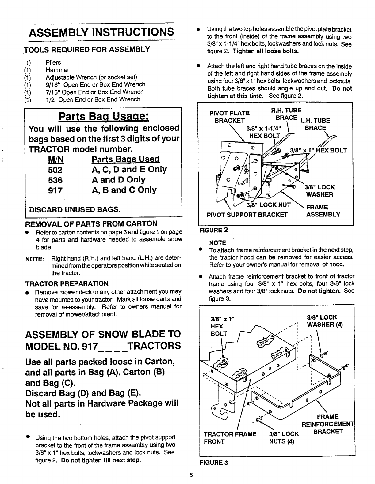
Using the two top holes assemble the pivot plate bracket
to the front (inside) of the frame assembly using two
3/8" x 1-1/4" hex bolts, Iockwashers and lock nuts. See
figure 2. Tighten all loose bolts.
Attach the left and right hand tube braces on the inside
of the left and right hand sides of the frame assembly
using four 3/8" x 1"hex bolts, lockwashers and locknuts.
Both tube braces should angle up and out. Do not
tighten at this time. See figure 2.
Parts BaQ Usaae:
You will use the following enclosed
bags based on the first 3 digits of your
TRACTOR model number.
Parts Baas Used
502
536
917
DISCARDUNUSED BAGS.
REMOVAL OF PARTS FROM CARTON
• Refer to carton contents on page 3 and figure 1on page
4 for parts and hardware needed to assemble snow
blade.
NOTE: Right hand (R.H.) and left hand (LH.) are deter-
mined from the operators position while seated on
the tractor.
TRACTOR PREPARATION
• Remove mower deck or any other attachment you may
have mounted to your tractor. Mark all loose parts and
save for re-assembly. Refer to owners manual for
removal of mower/attachment.
ASSEMBLY OF SNOW BLADE TO
A, C, D and E Only
A and D Only
A, B and C Only
PIVOT PLATE R.H. TUBE
BRACKET BRACE LH. TUBE
3/8" X 1-1/4" \ BRACE
HEX BOLT
- J-®Jr 318-LOCK
PIVOT SUPPORT BRACKET ASSEMBLY
FIGURE 2
NOTE
To attach frame reinforcement bracket in the next step,
the tractor hood can be removed for easier access.
Refer to your owneCs manual for removal of hood.
Attach frame reinforcement bracket to front of tractor
frame using four 3/8" x 1" hex bolts, four 3/8" lock
washers and four 3/8" lock nuts. Do not tighten. See
figure 3.
3/8" X 1"
HEX -'"
BOLT
3/8" LOCK
i
WASHER (4)
i
MODEL NO. 917 TRACTORS
Use all parts packed loose in Carton,
and all parts in Bag (A), Carton (B)
and Bag (C).
Discard Bag (D) and Bag (E).
Not all parts in Hardware Package will
be used.
O
Using the two bottom holes, attach the pivot support
bracket to the front of the frame assembly using two
3/8" x 1" hex bolts, lockwashers and lock nuts. See
figure 2. Do not tighten till next step.
,,
I
" REINFORCEMENT
_,_ FRAME
TRACTOR FRAME 3/8" LOCK BRACKET
FRONT NUTS (4)
FIGURE 3
Q
Lower the mower lift assembly.
!
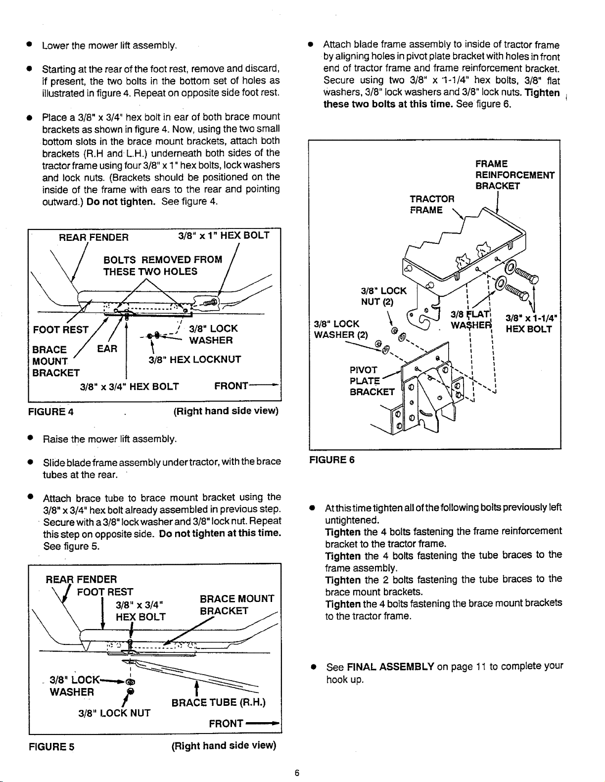
Starting at the rear of the foot rest, remove and discard,
if present, the two bolts in the bottom set of holes as
illustrated in figure 4. Repeat on opposite side foot rest.
O
Place a 3/8" x 3/4" hex bolt in ear of both brace mount
brackets as shown in figure 4. Now, using the two small
bottom slots in the brace mount brackets, attach both
brackets (R.H and LH.) underneath both sides of the
tractor frame using four 3/8" x 1" hex bolts, lock washers
and lock nuts. (Brackets should be positioned on the
inside of the frame with ears to the rear and pointing
outward.) Do not tighten. See figure 4.
REAR FENDER 3/8" x 1" HEX BOLT
BOLTS REMOVED FROM
THESE TWO HOLES
Attach blade frame assembly to inside of tractor frame
by aligning holes in pivot plate bracket with holes in front
end of tractor frame and frame reinforcement bracket.
Secure using two 3/8" x 1-1/4" hex bolts, 3/8" flat
washers, 3/8" lock washers and 3/8" lock nuts. Tighten 1
these two bolts at this time. See figure 8.
FRAME
REINFORCEMENT
BRACKET
TRACTOR !
3/8" LOCK
BRACE EAR
MOUNT 3/8" HEX LOCKNUT
BRACKET
3/8" x 3/4" HEX BOLT FRONT-----'-
FIGURE 4
• Raise the mower lift assembly.
• Slide bladeframe assembly undertractor, with the brace
tubes at the rear.
Attach brace tube to brace mount bracket using the
3/8" x 3/4" hex bolt already assembled in previous step.
•Secure with a3/8" lock washer and 3/8" lock nut. Repeat
this step on opposite side. Do not tighten at this time.
See figure 5.
REAR FENDER
\\ FOOT REST
- WASHER
3/8" x 3/4"
HEX BOLT
!
f
(Right hand side view)
BRACE MOUNT
BRACKET
NUT(2)
. \ 3/ L T! 3/.-x,-,-.
•(8'LO2K" @ _.._"" WA'_.HE_ H'_'BOLT
-'----_@ _'". _ I
t
P VOT ! ',
PLATE _'_ {_'b-\ _ ,'. ,
FIGURE 6
Atthis time tighten all of the following bolts previouslyleft
untightened.
Tighten the 4 bolts fastening the frame reinforcement
bracket to the tractor frame.
Tighten the 4 bolts fastening the tube braces to the
frame assembly.
Tighten the 2 bolts fastening the tube braces to the
brace mount brackets.
Tighten the 4 bolts fastening the brace mount brackets
to the tractor frame.
_ 3/8" LOCK
WASHER _ [
[ BRACE TUBE (R.H.)
3/8" LOCK NUT
FIGURE 5
• See FINAL ASSEMBLY on page 11 to complete your
hook up.
FRONT ,------1-
(Right hand side view)
 Loading...