

Page 1
Owner's Manual
48" DOZER BLADE
Model No. 486.244122
®
CAUTION:
Before using this product, read
this manual and follow all Safety
Rules and
Operating Instructions.
IMPORTANT - READ THIS FIRST!!!
For Missing Parts or Assembly Questions
Please Call 866-576-8388
Mon.-Fri. 7 am - 5 pm CST.
FAX 217-728-2032 or e-mail info@agri-fab.com
Missing parts will be sent UPS in 24 hours directly to your home.
Sears, Roebuck and Co., Hoffman Estates, IL 60179 U.S.A.
www.sears.com/craftsman
PRINTED IN U.S.A.
• Safety
• Assembly
• Operation
• Maintenance
• Parts
FORM NO. 49344 (REV. 7/04)
Page 2
SAFETY
Any power equipment can cause injury if operated improperly or if the user does not understand how to operate the
equipment. Exercise caution at all times, when using power equipment.
1. Read the tractor and dozer blade owners manuals and know how to operate your tractor before using the tractor with
the dozer blade attachment.
2. Never operate the tractor and dozer blade without wearing proper clothing suited to weather conditions and
operation of controls.
3. Never allow children to operate the tractor and dozer blade. Do not allow adults to operate without proper instructions.
4. Always begin with transmission in first (low) gear and gradually increase speed as required.
Look for this symbol to point out important safety precautions. It mean--Attention!!
Become alert!! Your safety is involved.
LIMITED ONE YEAR WARRANTY ON 48" DOZER BLADE
For one year from the date of purchase, when this Dozer Blade is maintained and lubricated according to the
operating and maintenance instructions in the owner's manual, Sears will repair any defect in material or
workmanship free of charge. If this Dozer Blade is used for commercial or rental purposes, this warranty applies for
only 90 days from the date of purchase.
This warranty does not cover repairs necessary because of operator negligence or abuse, including the failure to
maintain the equipment according to instructions contained in the owner's manual.
WARRANTY SERVICE IS AVAILABLE BY CONTACTING THE NEAREST SEARS SERVICE CENTER/DEPARTMENT IN THE UNITED STATES.
This warranty applies only while this product is in the United States.
This warranty gives you specific legal rights, and you may also have other rights which vary from state to state.
Sears, Roebuck and Co. D/817 WA. Hoffman Estates, Chicago, IL 60179
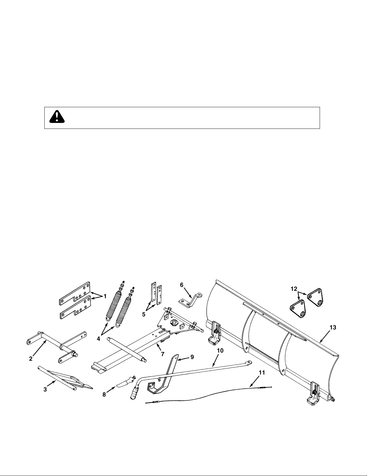
CARTON CONTENTS
1. Frame Brackets
2. Lift Assembly
3. Guide Bracket Assembly
4. Spring Assembly (2)
5. Angle Lock Bars (2)
6. Blade Pivot Bracket
7. Channel/Pivot Plate Assembly
8. Grip Assembly
9. Support Bracket
10. Handle Assembly w/Grip
2
11. Control Cable Assembly
12. Lift Pivot Plate (2)
13. Blade Assembly
Parts Package (See page 3)
Page 3
SHOWN FULL SIZE
A
B
W
C
D E F G H I J
K
L
M
N
O
P
Q
R
S
T
U
V
NOT SHOWN FULL SIZE
X
Y
Z AA
GG
BB
HH
DDCC EE
II
JJ KK
FF
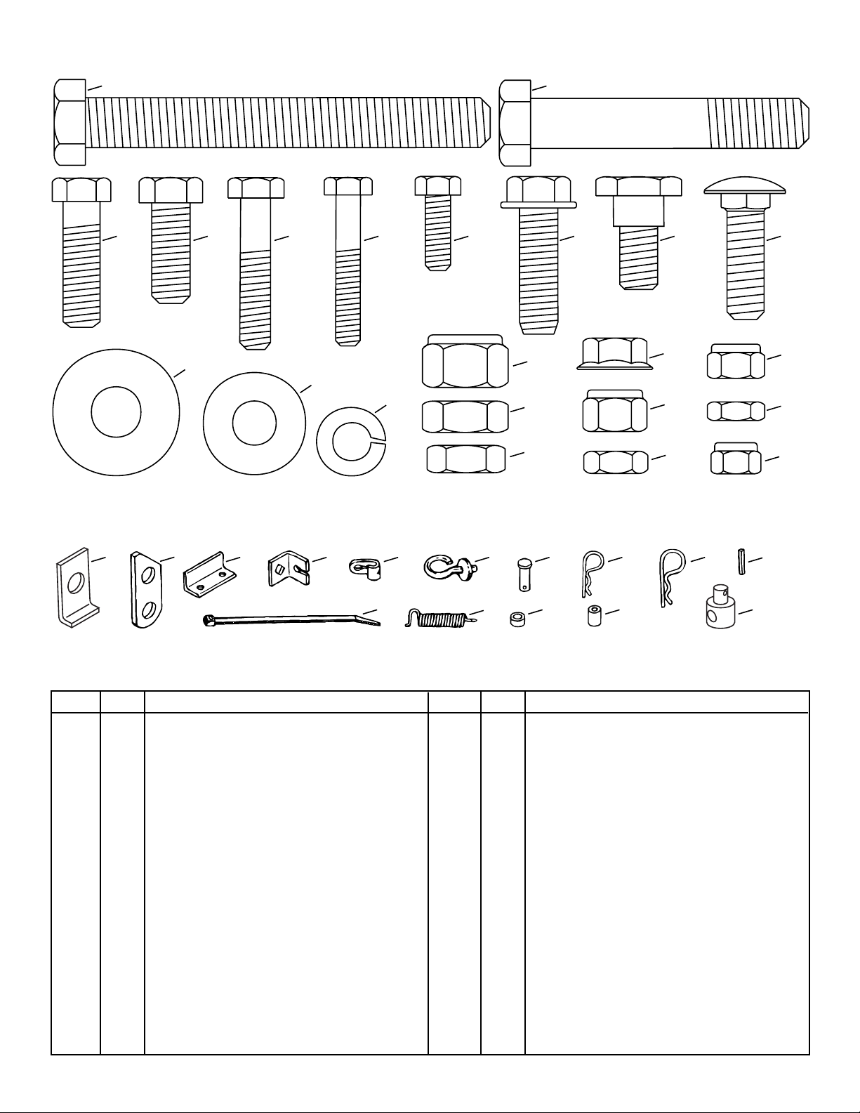
CONTENTS OF PARTS PACKAGE
REF. QTY. DESCRIPTION
A 1 Hex Bolt, 1/2" x 4"
B 2 Hex Bolt, 1/2" x 2-3/4"
C 9 Hex Bolt, 3/8" x 1-1/4"
D 1 Hex Bolt, 3/8" x 1"
E 1 Hex Bolt, 5/16" x 1-1/2"
F 1 Hex Bolt, 1/4" x 1-1/2"
G 1 Hex Bolt, 1/4" x 3/4"
H 2 Hex Bolt, 3/8" x 1" Thread Forming
I 1 Shoulder Bolt, (Special) 3/8" x 5/8"
J 2 Carriage Bolt, 3/8" x 1-1/4"
K 4 Flat Washer, 7/16" Std.
L 1 Flat Washer, 3/8" Std.
M 4 Lock Washer, 3/8"
N 2 Nylock Nut, 1/2"
O 2 Hex Jam Nut, 1/2"
P 4 Hex Jam Nut, 7/16"
Q 1 Whizlock Nut, 3/8"
R 10 NyLock Nut, 3/8"
REF. QTY. DESCRIPTION
S 2 Hex Jam Nut, 3/8"
T 1 Nyock Nut, 5/16"
U 4 Hex Jam Nut, 5/16"
V 3 Nyock Nut, 1/4"
W 2 Keeper Plate
X 1 Lift Arm Link
Y 1 Stop Angle
Z 1 Cable Mount Bracket
AA 2 Cable End Fitting
BB 1 Handle Guide
CC 4 Clevis Pin, 3/8" x 3/4"
DD 6 Hairpin Cotter, 3/32"
EE 10 Hairpin Cotter, 1/8"
FF 1 Spring Pin, 1/4" x 1"
GG 1 Nylon Tie
HH 1 Spring, Angle Lock
II 9 Spacer, Short
JJ 1 Spacer, Long
KK 2 Trunnion, Lift Rod
3
Page 4
4
Page 5
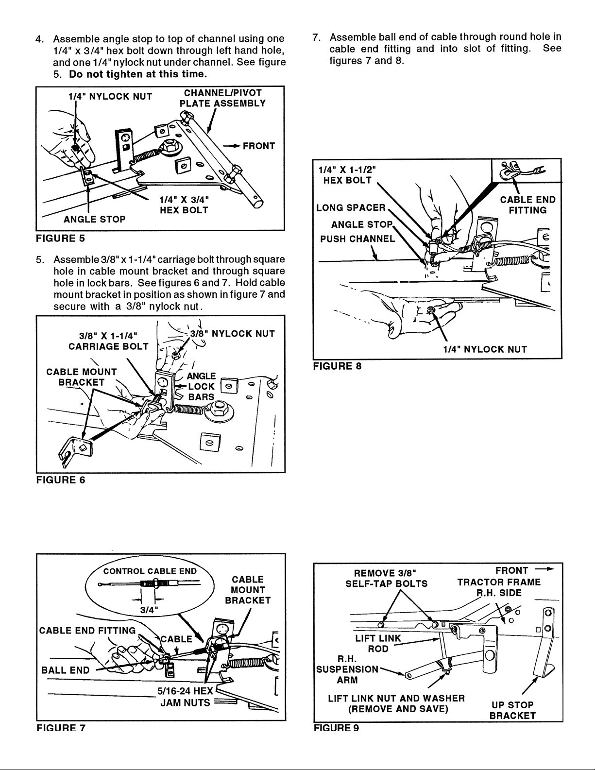
8. Attach cable end fitting and long spacer to right
hand hole in angle stop and channel using 1/4" x
1-1/2" hex bolt and 1/4" Nylock nut. Tighten both
1/4" Nylock nuts that secure the angle stop to the
channel. See figure 8. NOTE: Keep cable and
fitting in alignment with cable mount bracket
when tightening nuts.
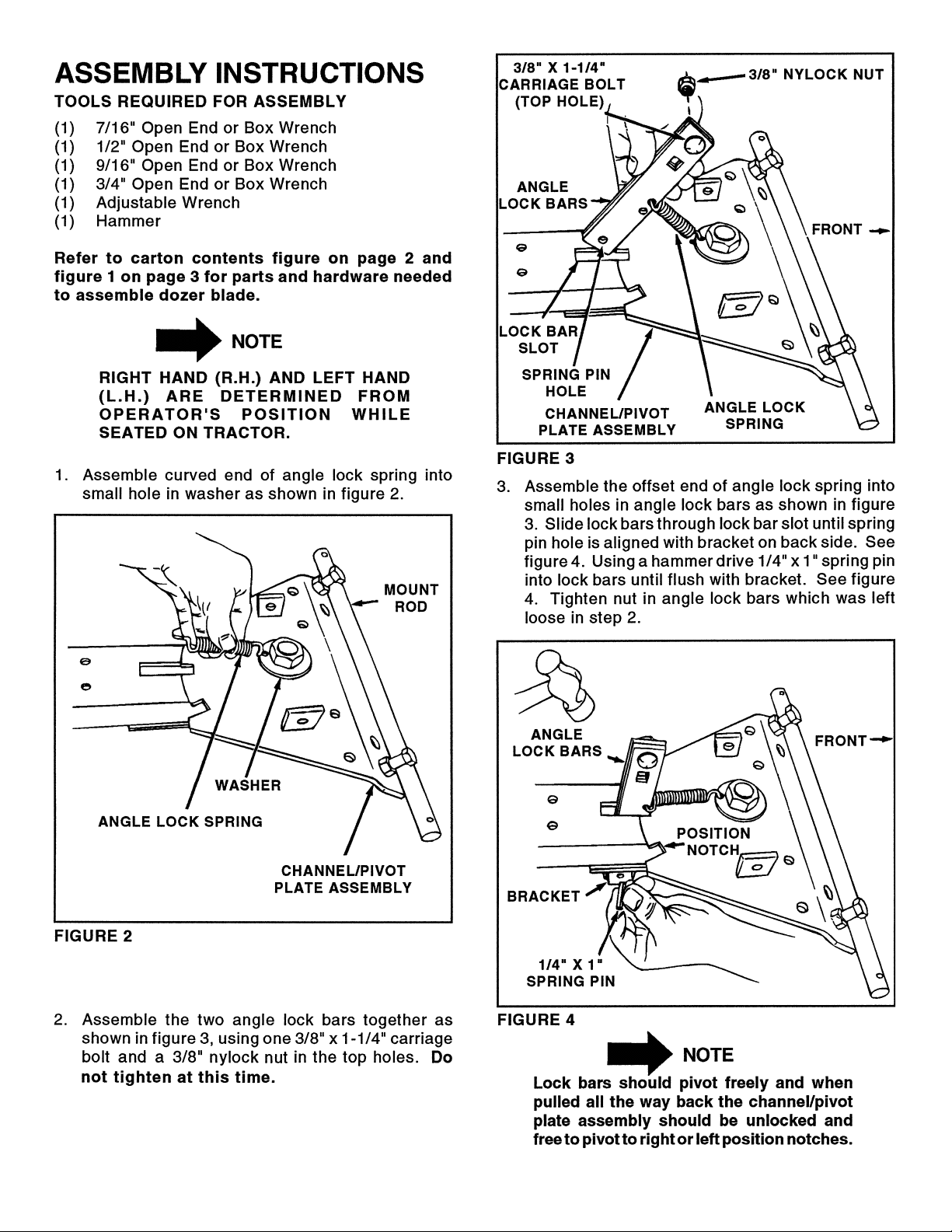
6. Assemble one 5/16-24 hex jam nut onto threaded
end of control cable approximately 3/4" from end.
Assemble threaded cable end through round hole
in cable mount bracket and secure with another
5/16-24 hex jam nut. See figure 7.
ASSEMBLY OF BLADE TO TRACTOR
TO PREPARE TRACTOR:
A. Remove the mower or any other attachment you
may have mounted to your tractor. Mark all loose
parts and save for re-assembly. Refer to tractor
owners manual for instructions on removal of the
mower or attachment.
B. Remove and save both suspension arms, along
with the nuts and washers which fasten them to
the lift link rods. Also remove the 3/8" self-tapping
bolts from each side of the tractor frame as shown
in figure 9. On some tractors the lift link nuts
will be reused to fasten the dozer blade lift
assembly to the lift link rods.
5
Page 6

6
Page 7

12. Assemble a lift rod trunnion (facing in) to each lift link
rod using either a, b or c:
a. two 7/16-20 hex jam nuts (48" mower decks)
b. a 3/8-16 Nylock nut and the original lock
nut you removed earlier (models before 1995).
c. a 3/8-24 hex jam nut and the original lock nut
you removed earlier (all other models)
The correct nuts will screw on easily. Tighten nuts so
that one thread of rod extends past bottom nut.
10. Assemble a frame bracket to the outside of the
tractor frame under the left foot rest. Use two 3/8"
x 1-1/4" hex bolts, two 3/8" lock washers and four
short spacers. Use two spacers on each bolt,
between the frame bracket and the tractor frame.
Use only one spacer on the rear bolt if it goes
through a sway bar bracket. See figure 15.
11. Assemble the lift pivot plate to the inside of the
frame bracket using two 3/8" x 3/4" clevis pins and
two small hairpin cotters. See figure 15.
FRONT
LEFT SIDE
CLEVIS PINS
3/8" x 3/4"
LIFT PIVOT
PLATE
3/8" x 1-1/4" BOLTS,
3/8" LOCK WASHERS
& SHORT SPACERS
FRAME BRACKET
HAIRPIN COTTER
(SMALL)
SWAY BAR BRACKET
FIGURE 15
7
Page 8

17. Move attachment lift lever all the way forward and lock
in position. See figure 28 on page 10.
18. Assemble lift arm link over channel rod and insert pivot
shaft end (from R.H. side of tractor) into hole in L.H. lift
pivot plate. Secure lift arm link to channel rod with 1/8"
(large) hairpin cotter. See figure 19.
19. Assemble a frame bracket under the right hand foot
rest of the tractor using two 3/8" x 1-1/4" hex bolts, two
3/8" lock washers and four short spacers. Use two
spacers on each bolt, between the frame bracket
and the tractor frame. See figure 19.
FRAME
BRACKET
HAIRPIN
COTTER
(SMALL)
HAIRPIN
COTTER
(LARGE)
FIGURE 21
RIGHT HAND SIDE VIEW
FRONT
LIFT
ASSEMBLY
PIVOT SHAFT
CLEVIS PINS
3/8" x 3/4"
LIFT PIVOT PLATE
22. Align two front holes in Support Bracket with holes
in front of foot rest on right side of tractor frame.
Remove any bolts present in holes, but leave all
brackets in place. Attach the Support Bracket using
two 3/8" x 1-1/4" hex bolts and 3/8" Nylock nuts. If
bolts won't fit, use 3/8" x 1" thread forming bolts
without the Nylock nuts. See figure 22.
8
Page 9

(2) 3/8" x 1"
THREAD FORMING
HEX BOLTS
3/8" x 1"
HEX BOLTS
(2) 3/8" x 1-1/4"
NYLOCK NUTS
FIGURE 22
or
HEX BOLTS
AND 3/8"
UP STOP BRACKETUP STOP BRACKET
HAIRPIN
HAIRPIN
COTTER
COTTER
SUPPORT
SUPPORT
BRACKET
BRACKET
HANDLE
GUIDE
9
Page 10

101112
Page 11

Page 12

LIFT ROD TRUNNION
AND HEX NUTS
HAIRPIN
COTTER
(SMALL)
HAIRPIN
COTTER
(LARGE)
FIGURE 32
LIFT ASSEMBLY
LIFT ARM
LINK
HAIRPIN
COTTER
CLEVIS PINS
3/8" x 3/4"
LIFT PIVOT PLATE
Page 13

13
Page 14

REPAIR PARTS FOR MODEL 486.244122 - 48" DOZER BLADE
14
Page 15

REPAIR PARTS FOR MODEL 486.244122 - 48" DOZER BLADE
PART NO. QTY. DESCRIPTION
37 43348 1 Angle Lock Spring
38 48106 1 Shoulder Bolt, Special 3/8-16 x 5/8"
NO.
REF.
39 44072 1 Hex Whizlock Nut 3/8-16
40 7071 1 Handle Grip 3/4"
41 43343 10 Hairpin Cotter 1/8"*
42 47810 1 Nylock Nut 5/16-18*
43 41596 2 Hex Bolt 1/2-13 x 2"*
44 712-0206 4 Hex Nut 1/2-13*
45 43510 2 Hex Bolt 1/2-13 x 2-3/4"*
46 712-0383 2 Nylock Nut, 1/2-13
47 710-0305 2 Carriage Bolt 3/8-16 x 1-1/4"*
48 43003 4 Lock Washer, Spring 3/8*
49 HA21362 10 Nylock Nut 3/8-16*
50 43648 1 Hex Bolt 1/4-20 x 1-1/2"*
51 43012 1 Hex Bolt 1/4-20 x 3/4"*
52 47189 3 Nylock Nut 1/4-20*
53 23658 1 Spacer, Long
54 43085 1 Hex Bolt 5/16-18 x 1-1/2"*
55 44044 4 Clevis Pin, 3/8" Dia. x 3/4" Lg.
56 43055 6 Hairpin Cotter 3/32"*
57 43087 9 Hex Bolt 3/8-16 x 1-1/4"*
58 43070 1 Washer 3/8 Std. Wrt.*
59 23625 9 Spacer, Short
60 43001 1 Hex Bolt 3/8-16 x 1"*
61 712-0256 4 Hex Jam Nut 5/16-24*
62 731-0869 1 Plastic Grip
63 43019 2 Hex Jam Nut 1/2-13*
64 43352 4 Washer 7/16 Std. Wrt.*
65 25301 2 Frame Bracket
49344 1 Owners Manual
66 46001 2 Lift Rod Trunnion
67 44684 2 Jam Nut, 3/8-24 Fine Thread
68 48183 4 Hex Jam Nut, 7/16-20 Fine Thread
69 HA23193 2 Hex Bolt, 3/8-16 x 1" Thread Forming
PART NO. QTY. DESCRIPTION
1 62554 1 48" Blade Ass'y.
2 R3132J 2 Shoe
NO.
REF.
3 44326 8 Carriage Bolt 5/16-18 x 1"*
4 43081 8 Washer 5/16 Std. Wrt.*
5 43086 8 Lock Washer, Spring 5/16*
6 43083 8 Hex Nut 5/16-18*
7 23639 1 Wear Plate 48"
8 62556 1 Pivot Plate Ass'y.
9 62944 1 Channel Ass'y.
10 710-0741 1 Hex Bolt 3/4-10 x 3-1/2"
11 1540-162 2 Washer 3/4"
12 40436 1 Hex Jam Nut 3/4-10*
14 40598 1 Hex Lock Nut 3/4-10
15 9466R 2 Blade Adjustment Spring
16 44071 2 Hex Bolt 3/8-16 x 3-1/2"
17 43015 4 Hex Nut 3/8-16*
18 44074 2 Plastic Cap, 3/8"
19 62868 1 Guide Bracket Ass'y.
20 23646 1 Blade Pivot Bracket
21 62560 1 Tube Handle Ass'y.
15
22 62561 1 Release Grip Ass'y.
23 746-0366 1 Control Cable Ass'y
24 62562 1 Handle Guide
25 23728 1 Support Bracket
26 62951 1 Lift Ass'y.
27 45100 1 Hex Bolt 1/2-13 x 4"*
28 23922 2 Lift Pivot Plate
29 23655 1 Stop Angle
30 23624 2 Keeper Plate
31 23151 2 Angle Lock Bar
32 23631 1 Lift Arm Link
33 43349 1 Spring Pin 1/4 x 1"*
34 05762 1 Cable Mount Bracket
35 726-0178 1 Nylon Tie (Cable)
36 746-0260 2 Cable Fitting, End
*Purchase common hardware locally.
Page 16

Get it fixed, at your home or ours!
For repair of major brand appliances in your own home…
no matter who made it, no matter who sold it!
1-800-4-MY-HOME
(1-800-469-4663)
www.sears.com
SM
Anytime, day or night
To bring in products such as vacuums, lawn equipment and electronics
for repair, call for the location of your nearest
1-800-488-1222
www.sears.com
Sears Parts & Repair Center.
Anytime, day or night
For the replacement parts, accessories and owner’s manuals
that you need to do-it-yourself, call Sears PartsDirect
1-800-366-PART
(1-800-366-7278)
www.sears.com/partsdirect
6 a.m. – 11 p.m. CST,
7 days a week
SM
!
To purchase or inquire about a Sears Service Agreement:
1-800-827-6655
7 a.m. – 5 p.m. CST, Mon. – Sat.
Para pedir servicio de reparación a domicilio,
y para ordenar piezas con entrega a domicilio:
1-888-SU-HOGAR
(1-888-784-6427)
SM
HomeCentral
® Registered Trademark / ™ Trademark of Sears, Roebuck and Co.
© Sears, Roebuck and Co.
® Marca Registrada / ™ Marca de Fábrica de Sears, Roebuck and Co.
Au Canada pour service en français:
1-877-LE-FOYER
(1-877-533-6937)
SM
SM
 Loading...