

Craftsman 486244121 Owner’s Manual
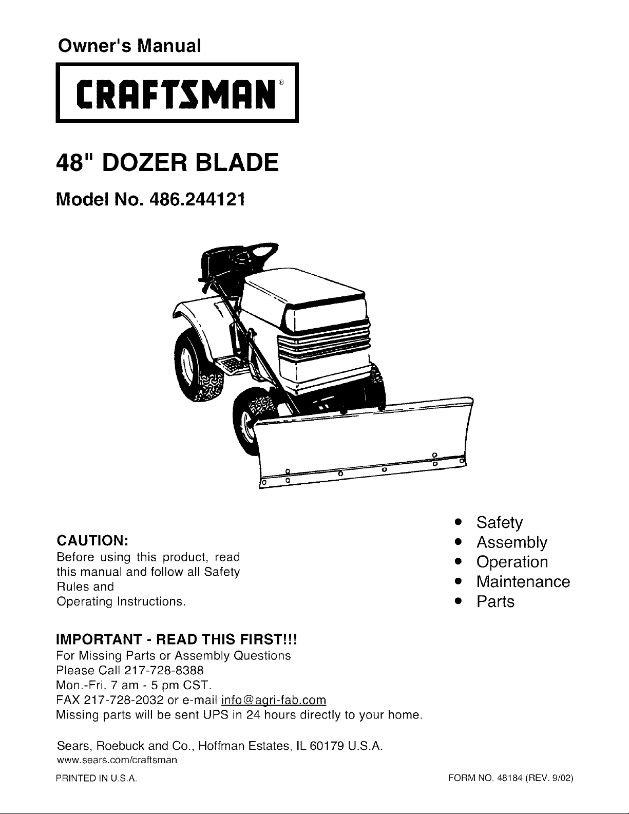
Owner's Manual
CRAFTSMAN+
48" DOZER BLADE
Model No. 486.244121
• Safety
CAUTION:
Before using this product, read
this manual and follow all Safety
Rules and
Operating Instructions.
IMPORTANT - READ THIS FIRST!!!
For Missing Parts or Assembly Questions
Please Call 217-728-8388
Mon.-Fri. 7 am - 5 pm CST.
FAX 217-728-2032 or e-mail info@agri-fab.com
Missing parts will be sent UPS in 24 hours directly to your home.
Sears, Roebuck and Co., Hoffman Estates, IL 60179 U.S.A.
www.sears.com/craftsman
PRINTED IN U.S.A. FORM NO. 48184 (REV. 9/02)
• Assembly
• Operation
• Maintenance
• Parts
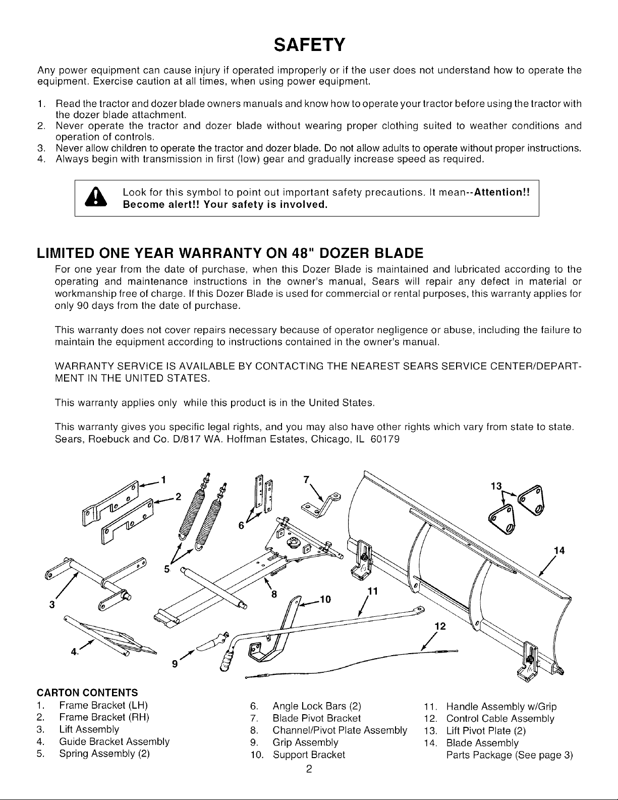
SAFETY
Any power equipment can cause injury if operated improperly or if the user does not understand how to operate the
equipment. Exercise caution at all times, when using power equipment.
1. Read the tractor and dozer blade owners manuals and know how to operate your tractor before using the tractor with
the dozer blade attachment.
2. Never operate the tractor and dozer blade without wearing proper clothing suited to weather conditions and
operation of controls.
3. Never allow children to operate the tractor and dozer blade. Do not allow adults to operate without proper instructions.
4. Always begin with transmission in first (low) gear and gradually increase speed as required.
Look for this symbol to point out important safety precautions. It mean--Attention!!
Become alert!! Your safety is involved.
LIMITED ONE YEAR WARRANTY ON 48" DOZER BLADE
For one year from the date of purchase, when this Dozer Blade is maintained and lubricated according to the
operating and maintenance instructions in the owner's manual, Sears will repair any defect in material or
workmanship free of charge. If this Dozer Blade is used for commercial or rental purposes, this warranty applies for
only 90 days from the date of purchase.
This warranty does not cover repairs necessary because of operator negligence or abuse, including the failure to
maintain the equipment according to instructions contained in the owner's manual.
WARRANTY SERVICE IS AVAILABLE BY CONTACTING THE NEAREST SEARS SERVICE CENTER/DEPART-
MENT IN THE UNITED STATES.
This warranty applies only while this product is in the United States.
This warranty gives you specific legal rights, and you may also have other rights which vary from state to state.
Sears, Roebuck and Co. D/817 WA. Hoffman Estates, Chicago, IL 60179
7
14
11
/
12
CARTON CONTENTS
1. Frame Bracket (LH)
2. Frame Bracket (RH)
3. Lift Assembly
4. Guide Bracket Assembly
5. Spring Assembly (2)
6. Angle Lock Bars (2)
7. Blade Pivot Bracket
8. Channel/Pivot Plate Assembly
9. Grip Assembly
10. Support Bracket
2
11. Handle Assembly w/Grip
12. Control Cable Assembly
13. Lift Pivot Plate (2)
14. Blade Assembly
Parts Package (See page 3)
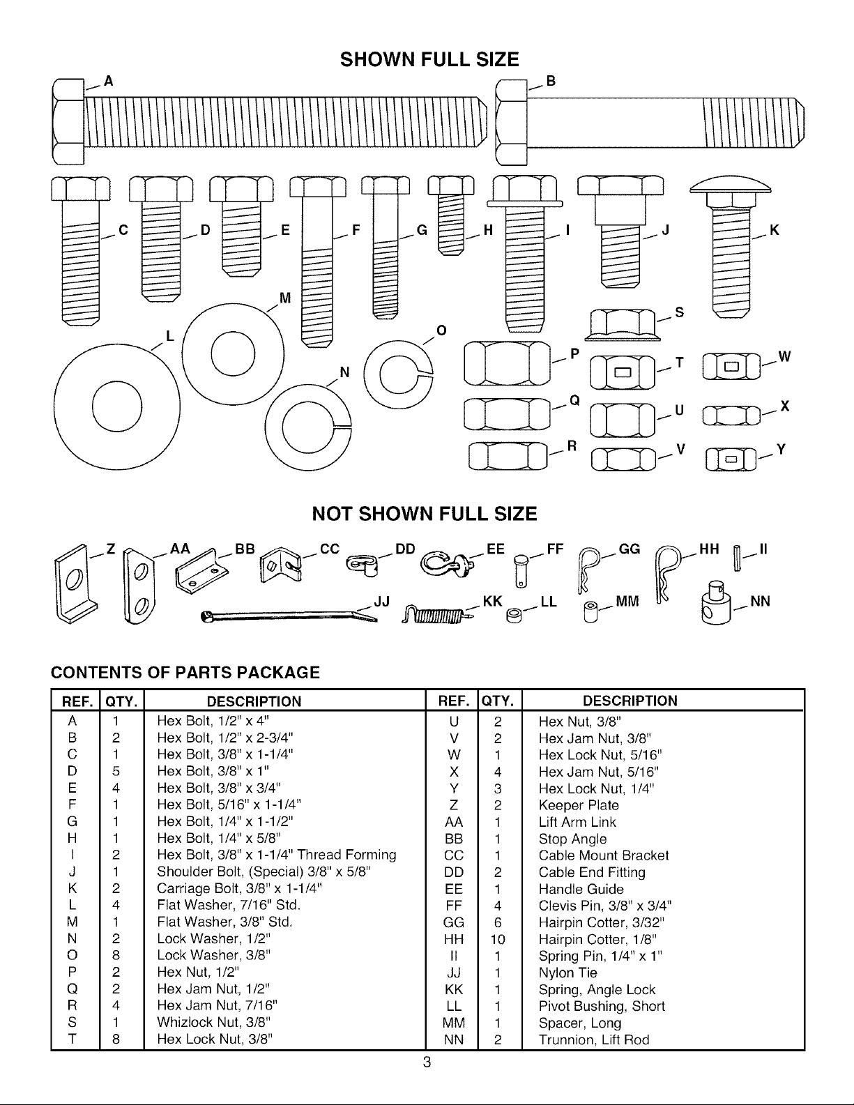
SHOWN FULL SIZE
;===.*..,.,=_
t
I
I
I
M
I
N
C[ZD Ix
CONTENTS OF PARTS PACKAGE
REF. QTY.
A 1
B 2
C 1
D 5
E 4
F 1
G 1
H 1
I 2
J 1
K 2
L 4
M 1
N 2
O 8
P 2
Q 2
R 4
S 1
T 8
Hex Bolt, 1/2" x 4" U 2
Hex Bolt, 1/2" x 2-3/4" V 2
Hex Bolt, 3/8" x 1-1/4" W 1
Hex Bolt, 3/8" x 1" X 4
Hex Bolt, 3/8" x 3/4" Y 3
Hex Bolt, 5/16" x 1-1/4" Z 2
Hex Bolt, 1/4" x 1-1/2" AA 1
Hex Bolt, 1/4" x 5/8" BB 1
Hex Bolt, 3/8" x 1-1/4" Thread Forming CC 1
Shoulder Bolt, (Special) 3/8" x 5/8" DD 2
Carriage Bolt, 3/8" x 1-1/4"
Flat Washer, 7/16" Std.
Flat Washer, 3/8" Std.
Lock Washer, 1/2"
Lock Washer, 3/8"
Hex Nut, 1/2"
Hex Jam Nut, 1/2"
Hex Jam Nut, 7/16"
Whizlock Nut, 3/8"
Hex Lock Nut, 3/8"
DESCRIPTION REF. QTY.
NOT SHOWN FULL SIZE
EE 1
FF 4
GG 6
HH 10
II 1
JJ 1
KK 1
LL 1
MM 1
NN 2
DESCRIPTION
Hex Nut, 3/8"
Hex Jam Nut, 3/8"
Hex Lock Nut, 5/16"
Hex Jam Nut, 5/16"
Hex Lock Nut, 1/4"
Keeper Plate
Lift Arm Link
Stop Angle
Cable Mount Bracket
Cable End Fitting
Handle Guide
Clevis Pin, 3/8" x 3/4"
Hairpin Cotter, 3/32"
Hairpin Cotter, 1/8"
Spring Pin, 1/4" x 1"
Nylon Tie
Spring, Angle Lock
Pivot Bushing, Short
Spacer, Long
Trunnion, Lift Rod
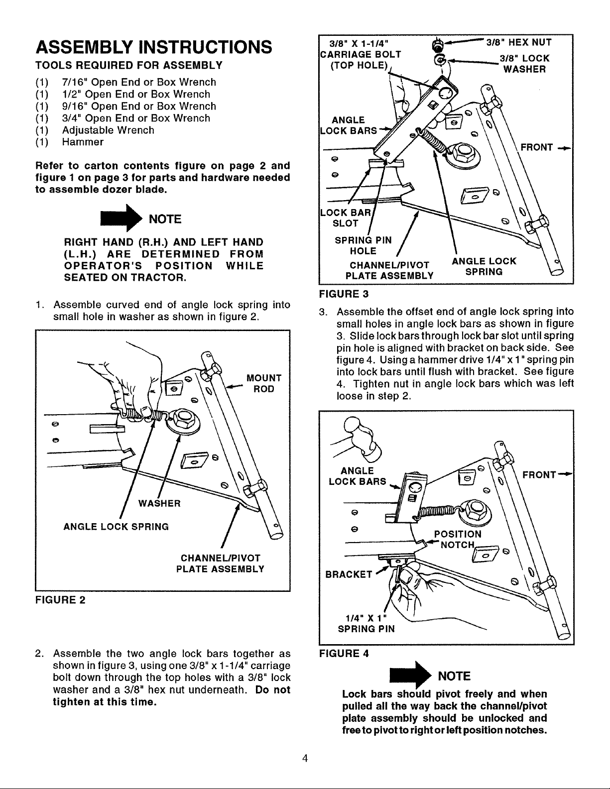
ASSEMBLY INSTRUCTIONS
TOOLS REQUIRED FOR ASSEMBLY
(1) 7/16" Open End or Box Wrench
(1) 1/2" Open End or Box Wrench
(1) 9/16" Open End or Box Wrench
(1) 3/4" Open End or Box Wrench
(1) Adjustable Wrench
(1) Hammer
Refer to carton contents figure on page 2 and
figure I on page 3 for parts and hardware needed
to assemble dozer blade.
3/8" X 1-114"
DARRIAGE BOLT
(TOP HOLE
ANGLE
LOCK BARS
_,_.--''_3_"HEX NUT
(_ 3/8"LOCK
WASHER
NOTE
RIGHT HAND (R.H.) AND LEFT HAND
(L.H.) ARE DETERMINED FROM
OPERATOR'S POSITION WHILE
SEATED ON TRACTOR.
.
Assemble curved end of angle lock spring into
small hole in washer as shown in figure 2.
.OCK BAR
SLOT
SPRING PIN
HOLE
CHANNEL/PIVOT
PLATE ASSEMBLY
FIGURE 3
.
Assemble the offset end of angle lock spring into
small holes in angle lock bars as shown in figure
3. Slide lock bars through lock bar slot until spring
pin hole is aligned with bracket on back side. See
figure 4. Using a hammer drive 1/4" x 1"spring pin
T
into lock bars until flush with bracket. See figure
4. Tighten nut in angle lock bars which was left
loose in step 2.
ANGLE LOCK
SPRING
/
ANGLELOCKSPR,NG /
CHANNEL/PIVOT
PLATE ASSEMBLY
FIGURE 2
,
Assemble the two angle lock bars together as
shown in figure 3, using one 3/8" x 1-1/4" carriage
bolt down through the top holes with a 3/8" lock
washer and a 3/8" hex nut underneath. Do not
tighten at this time.
FIGURE 4
rs_ NOTE
Lock ba pivot freely and when
pulled all the way back the channel/pivot
plate assembly should be unlocked and
free to pivot to right or left position notches.
4,
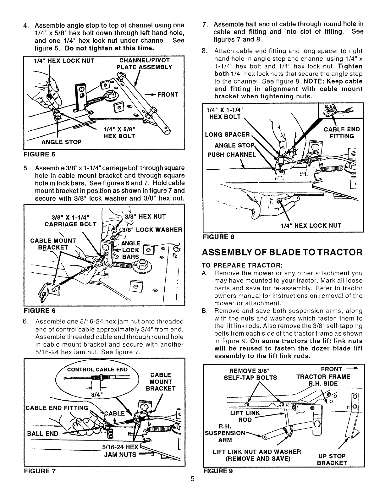
Assemble angle stop to top of channel using one
1/4" x 5/8" hex bolt down through left hand hole,
and one 1/4" hex lock nut under channel. See
figure 5. Do not tighten at this time.
114" HEX LOCK NUT
CHANNEUPIVOT
PLATE ASSEMBLY
FRONT
7,
Assemble ball end of cable through round hole in
cable end fitting and into slot of fitting. See
figures 7 and 8.
.
Attach cable end fitting and long spacer to right
hand hole in angle stop and channel using 1/4" x
1-1/4" hex bolt and 1/4" hex lock nut. Tighten
both 1/4" hex lock nuts that secure the angle stop
to the channel. See figure 8. NOTE: Keep cable
and fitting in alignment with cable mount
bracket when tightening nuts.
1/4" X 1-1/4"
HEX BOLT
1/4" X 518"
HEX BOLT
ANGLE STOP
FIGURE 5
.
Assemble 3/8" x 1-1/4" carriage bolt through square
hole in cable mount bracket and through square
hole in lock bars. See figures 6 and 7. Hold cable
mount bracket in position as shown in figure 7 and
secure with 3/8" lock washer and 3/8" hex nut.
,1
3/8" X 1-114" 3/8" HEX NUT
CARRIAGE BOLT
\ /
CABLE MOUNT ANGLE
BRACKET
FIGURE 6
6. Assemble one 5/16-24 hexjam nut onto threaded
end of control cable approximately 3/4" from end.
Assemble threaded cable end through round hole
in cable mount bracket and secure with another
5/16-24 hex jam nut. See figure 7.
LOCK WASHER
CABLE END
LONG SPACER%
ANGLE
PUSH CHANNEL
FITTING
-'% _
1/4" HEX LOCK NUT
FIGURE 8
ASSEMBLY OF BLADE TO TRACTOR
TO PREPARE TRACTOR:
A. Remove the mower or any other attachment you
may have mounted to your tractor. Mark all loose
parts and save for re-assembly. Refer to tractor
owners manual for instructions on removal of the
mower or attachment.
B. Remove and save both suspension arms, along
with the nuts and washers which fasten them to
the lift link rods. Also remove the 3/8" self-tapping
bolts from each side of the tractor frame as shown
in figure 9. On some tractors the lift link nuts
will be reused to fasten the dozer blade lift
assembly to the lift link rods.
BALL E__ _
5/16"24 HE _ [
JAM NUTS _
FIGURE 7
CABLE
MOUNT
J BRACKET
REMOVE 3/8"
SELF-TAP BOLTS
TRACTOR FRAME
FRONT
R.H. SIDE
ARM
'
LIFT LINK NUT AND WASHER
(REMOVE AND SAVE)
FIGURE 9
UP STOP
BRACKET
 Loading...