

Craftsman 486244071 Owner’s Manual
owners
monuo_
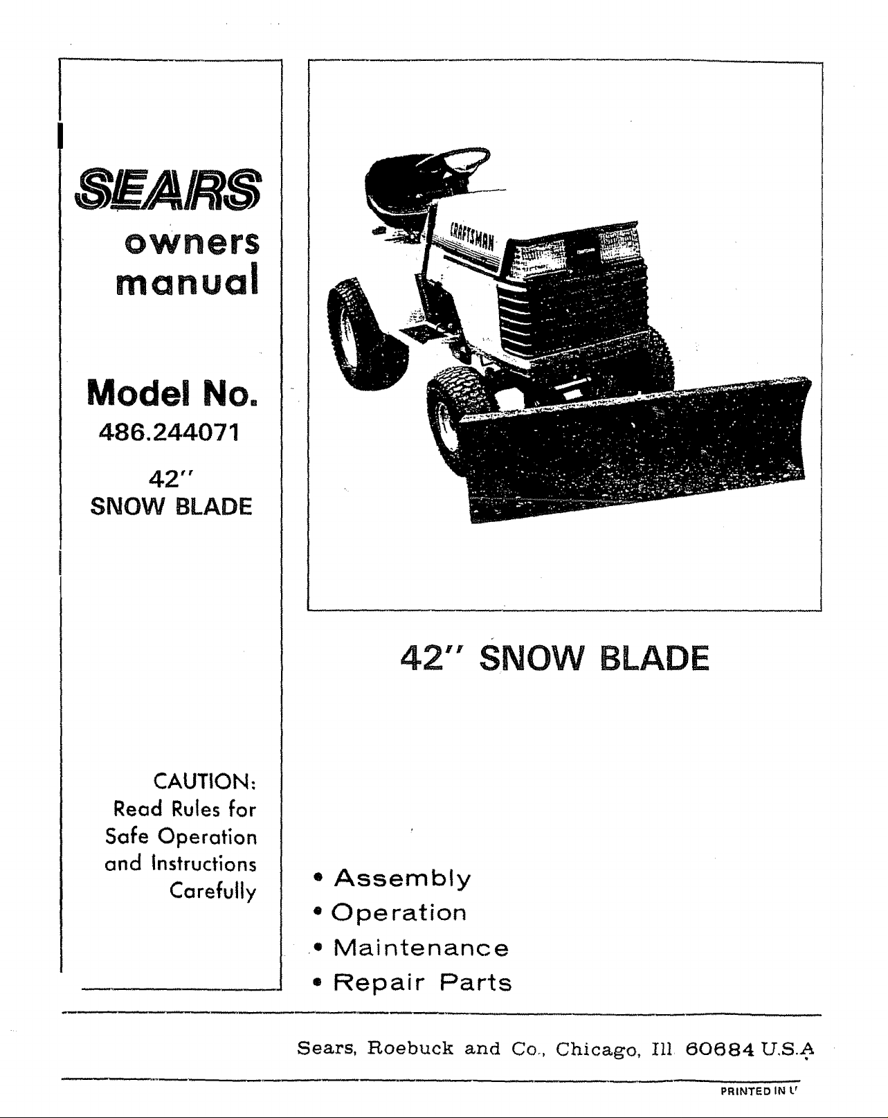
Model No.
486.244071
42'"
SNOW BLADE
CAUTION:
Read Rules for
Safe Operation
and Instructions
Carefully
42"" SNOW BLADE
,, Assembly
" Operation
• Maintenance
• Repair Parts
Sears, Roebuck and Co, Chicago, Ill, 60684 U,S.A
PRINTED IN U
RULES FOR SAFE OPERATIONS
Remember; any power equipment can cause injury if operated improperly or if the user-does not.understand how to operate
the equipment.
IMPORTANT SAFETY PRECAUTIONS. IT
MEANS - ATTENTION! BECOME ALERTI
LOOK FOR THIS SYMBOL TO POINT OUT
YOUR SAFETY IS INVOLVED,
Exercise caution at all times, when using power equipment,
1. Read the tractor and snow blade owners manuals and know how to operate your tractor, before using tractor with
snow blade attachment.
2o Never operate tractor and snow blade without wearing proper clothing suited to weather conditions and operation of
controls.
3, Never allow children to operate tractor and snow blade, and do not allow adults to operate without proper instructions.
4. Always begin with transmission in first (low) gear and engine at Eowspeed, and gradually increase speed'as required.
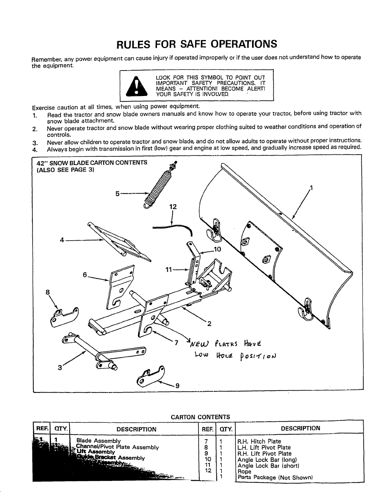
42" SNOW BLADE CARTON CONTENTS
(ALSO SEE PAGE 3)
5
12
8
2
3
CARTON CONTENTS
DESCRIPTION
Blade Assembly
Aa_embly
DESCRIPTION
Plate Assembly
Assembly
7 1
8 _
9 1
lo 1
1t 1
t2 1
R.H. Hitch Plate
LH, Lift Pivot Plate
R,H. Lift Pivot Plate
Angle Lock Bar (long)
Angle Lock Bar (shor_)
Rope
Parts Package (Not Shown)
D
Q R R T
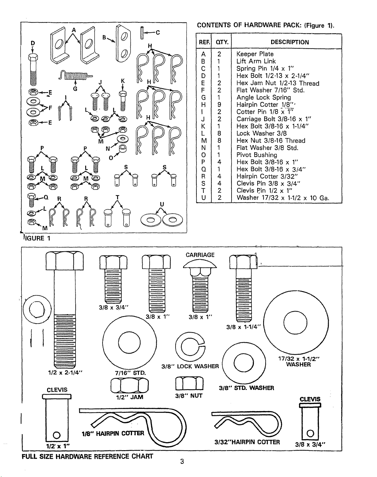
CONTENTS OF HARDWARE PACK: (Figure 1)_
RER
H
U
QTY.
A
2
B
1
C
1
D
1
E
2
F
2
1
G
H
9
2
l
J
2
K
1
L
8
M
8
N
1
1
0
P
4
Q
1
4
R
S
4
T
2
2
U
Keeper Plate
Lift Arm Link
Spring Pin 1/4 x t"
Hex Bolt 1t2-13 x 2-114"
Hex Jam Nut 1/243 Thread
Flat Washer 7/16" Std,
Angle Lock Spring
Hairpin Cotter 1/8""
Cotter Pin 1/8 x 1"
Carriage Bolt 3/8-16 x 1"
Hex Bolt 3/8-16 x 1-1/4"
Lock Washer 3/8
Hex Nut 3/8-16 Thread
Flat Washer 3/8 Std.
Pivot Bushing
Hex Bott 3/8-16 x 1"
Hex Bolt 3/8-16 x 3/4"
Hairpin Cotter 3/32"
Clevis Pin 3/8 x 3/4"
Clevis P.in 1/2 x 1"
Washer 17/32 x 1-1/2 x 10 Ga,
DESCRIPTION
IGURE 1
3/8 x 3/4"
1/2 x 2-1t4" 7/16" STD.
CLEVIS
["' J 1/2" JAM
!
I
3/8 x 1"
318" LOCK WASHER
3/8"" NUT
CARRIAGE
3/8 x 1"
3/8 x 1-1/4"
17132 x 1-1/2"
WASHER
318"' STD. WASHER
CLEVIS
' t
I °
FULL SlZE HARDWARE REFERENCE CHART
1/2' x 1"
3t32"HAIRPIN COTTER
3/8 x 3/4"
ASSEMBLY INSTRUCTIONS
TOOLS REQUIRED FOR ASSEMBLY
(1) Pliers
(1) Hammer
(1) 1/2" Open End or Box Wrench
(1) 9/16" Open End or' Box Wrench
(1) 3/4," Open End or Box Wrench
(t) Adjustable Wrench
Refer to carton contents figure on page 2 and figure
1 on page 3 for parts and hardware needed to
assemble snow blade,
.
Using a hammer drive 1/4" x 1" spring pin
through slot in bracket and hole in end of lock
bars until flush with bracket. See figure 3,
Tighten 3/8" hex nets left loose in step 1o
ASSEMBLY OF SNOW BLADE
TO LAWN TRACTOR.
Remove mower or any other attachment you may
have mounted to your tractor. Mark all loose parts
and save for re-assembly. Refer to owners manual
for removal of mower/attachment,
NOTE
RIGm' HAND (R.H.) AND LEFT HAND
(Loll.) ARE DETERMINED FROM
OPERATOR'S POSITION WHILE
SEATED ON TRACTOR.
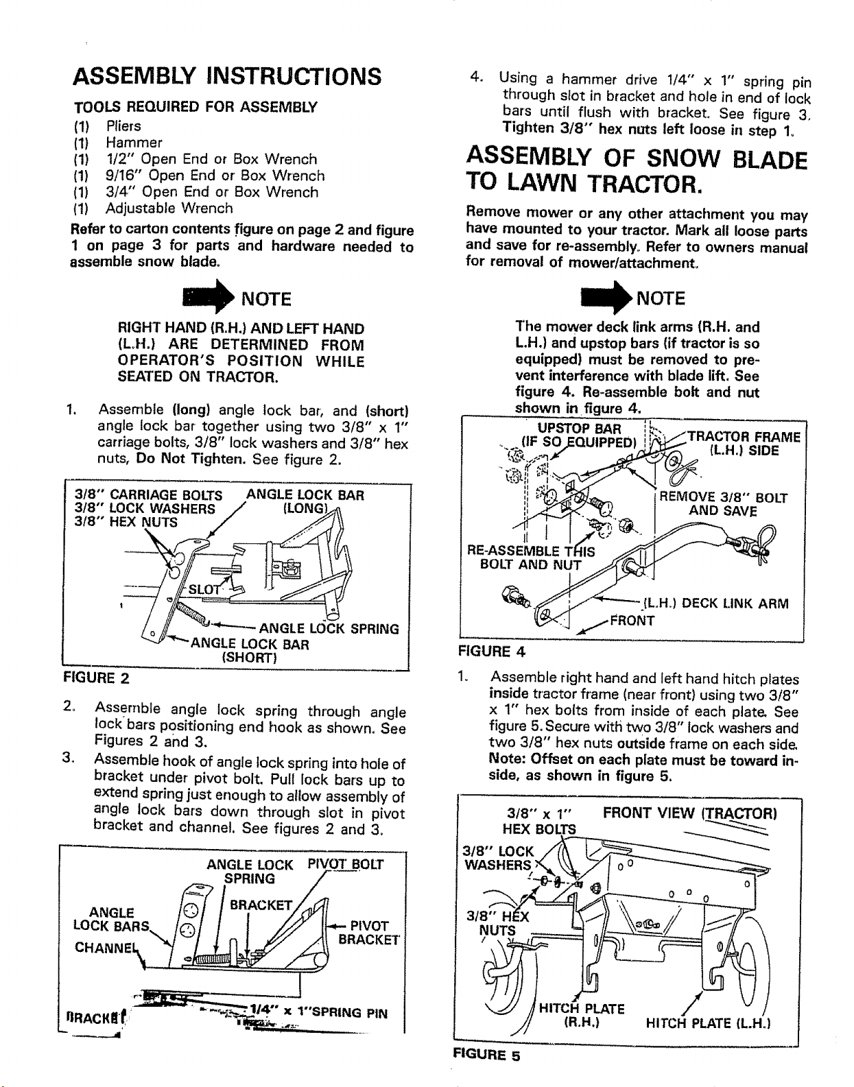
, Assemble (long) angle lock bar, and (short)
angle lock bar together using two 3/8" x 1"
carriage bolts, 3/8" lock washers and 3/8" hex
nuts, Do Not Tighten, See figure 2.
3/8"' CARRIAGE BOLTS ANGLE LOCK BAR
3/8" LOCK WASHERS// (LO G,_
3/8" HEX NUTS / ,_
/
N '
/
/o//_ LOCKSPRING
_J_"_"ANGLE LOCK BAR
(SHORT)
FIGURE 2
22
Assemble angle lock spring through angle
lock bars positioning end hook as shown. See
Figures 2 and 3.
3_
Assemble hook of angle lock spring into hole of
bracket under pivot bolt. Pull lock bars up to
extend spring just enough to allow assembly of
angle lock bars down through slot in pivot
bracket and channel. See figures 2 and 3,
ANGLE LOCK PIVOT BOLT
I_ NOTE
The mower deck link arms (R.H. and
L,H,) and upstop bars (if tractor is so
equipped) must be removed to pre-
vent interference with blade lift, See
figure 4. Re-assemble bolt and nut
shown in figure 4,
UPSTOP BAR ,_ .. /-rD^t.T_n ==3^..."
tJr ouF._ulrrr-uI ! '1_ t/u t _ln=
il S:_ ,,
_,__ _REMOVE 3t8 BOLT
RE-ASSEMBLE THIS _ l/
BOLT_AND _ ..... °-
_ ;_/_---_ {L,H,)DECK LINK ARM
_<_. ;J/FRONT
FIGURE 4
Assemble right hand and left hand hitch plates
inside tractor frame (near front) using two 3/8"
x 1" hex bolts from inside of each plate, See
figure 5,Secure witf_ two 3/8" lock washers and
two 3/8" hex nuts outside frame on each side,
Note: Offset on each plate must be toward in-
side, as shown in figure 5.
3/8"' x 1"'
HEX BOLTS
3/8"' LOCK
FRONT VIEW (TRACTOR)
SPRING __'
L_(G_R S _ / BR_CKET_=.- P|VOT
_-_/<:_/ in | _(/'./: /_!" BRACKET
CHANNEI_. /_
==.... ..j " x 1"'SPRING PIN
3/8" H_X
NUTS
FIGURE 5
./_ HITCH PLATE
(R,H.) HITCH PLATE (L.Ho)
 Loading...