

Craftsman 486244040, 48624404 Owner’s Manual
OWNERS
MANUAL
Model No.
486.244040
48"
SNOW BLADE
CRI:tFTSMI:IN
CAUTION:
Read Rules for
Safe Operation
and Instructions
Carefully
48" SNOW BLAD
Sears, Roebuck and Co., Hoffman Estates, IL. 60179 U.S.A.
PRINTED tN U,S.A.
RULES FOR SAFE OPERATION
Any power equipment can cause injury if opprated improperly or ifthe user does not understand how to operate the equipment.
LOOK FOR THIS SYMBOL TO POINT OUT
IMPORTANT SAFETY PRECAUTIONS. IT
MEANS--ATTENTION! BECOMEALERT! YOUR
SAFETY IS INVOLVED.
Exercise caution at all times, when using power equipment.
1, Read thetractor and snow blade owners manuats and know howto operate your tractor before using tractor Withsnow blade
attachment. " • . + •
2. Never operate tractorand snow blade without wearing proper clothing suited to +weather conditions and operation of
controls. ++
3. Never aliow children to"operate tractor and snow blade, and do+not all0w adutts to operate witt_out proper instructions. "
4. AlwaYs begin with transmission in first (low) gear and gradually increase speed as required:
CONGRATULATIONS on your purchase of a Sears snow
blade. It has been designed, manufactured and engi-
neered to give you the best possible dependability and
performance.
Should you experience any problem you can not easily
remedy, please contact your nearest Sears Service Cen-
ter/Department. We have competent well trained techni-
cians and the proper tools to service or repair this snow
blade.
Please read and retain this manual. The instructions will
enable you to assemble and maintain your snow blade
properly. Always observe the "SAFETY RULES". !
TABLE OF CONTENTS
SAFETY RULES...I ........................................................... 2
CUSTOMER RESPONSIBILITIES ................................... _2
ACCESSORIES .................................................................. 3
CARTON CONTENTS ................................................... 3-4
ASSEMBLY FOR 917-. SERIES ............................... _.4-6
ASSEMBLY FOR 502-. SERIES ................................ ...6-8
MAINTENANCE AGREEMENT
• A Sears maintenance agreement is avaitable on this
snow blade. Contact your nearest Sears store for
details.
CUSTOMER RESPONSIBILITIES
• Read and observe the safety rules.
• Foltow the instructions under "Customer Responsibili-
ties" and "Storage" sections of this manual.
ASSEMBLY FOR 536... SERIES ................................... 8-9
UNIVERSAL FINAL ASSEMBLY ................................. 9+12
OPERATION AND ADJUSTMENTS .......................... 12-13
STORAGE ....................................................................... 13
PARTS EXPLOSION ....................................................... 14
REPAIR PARTS .............................................................. 15
PARTS ORDERING/SERVICE .................... BACK COVER
2
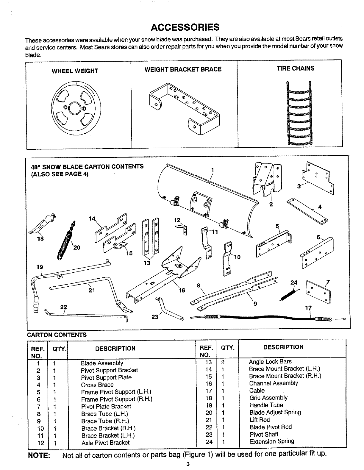
ACCESSORIES
These accessories were available when your snow blade was purchased, They are also available at most Sears retail outlets
and service centers. Most Sears stores can also order repair parts for you when you provide the model number of your snow
blade.
WHEEL WEIGHT
48" SNOW BLADE CARTON CONTENTS
(ALSO SEE PAGE 4)
18
WEIGHT BRACKET BRACE
TIRE CHAINS
I
CARTON
REF.
NO.
1
2
3
4
5
6
7
8
9
10
11
12
CONTENTS
QTY.
1
1
1
1
1
1
1
1
1
1
1
1
13
8
16
c_====_mmm__-
DESCRIPTION REF.
NO.
Biade Assembly 13
Pivot Support Bracket 14
Pivot Support Plate 15
Cross Brace 16
Frame Pivot Support (L.H,) 17
Frame Pivot Support (R.H.) 18
Pivot P_ate Bracket 19
Brace Tube (L,H+) 20
Brace Tube (R.H.) 21
Brace Bracket (R,H.) 22
Brace Bracket (L+H+) 23
Axle Pivot Bracket 24
QTY.
2
1
!
1
1
1
1
1
1
1
!
1
24
i
9
DESCRIPTION
AngleLock Bars
Brace Mount Bracket (L.H.)
Brace Mount Bracket (R.H.)
Channel Assembly
Cable
Grip Assembly
Handle Tube
Blade Adjust Spring
Lift Rod
Blade Pivot Rod
Pivot Shaft
Extension Spring
17
!,
NOTE:
Not all of carton contents or parts bag (Figure 1)
3
will
be used for one particular fit up.
.-_ F--®®! -- ®®®®®
A_
®®®®@""
@®@®®
®®@@@®
®®@@@
®®®®®®
(_ _(__ _-_ AE'--I
AA--Q@ @ @ Ac_ __...___
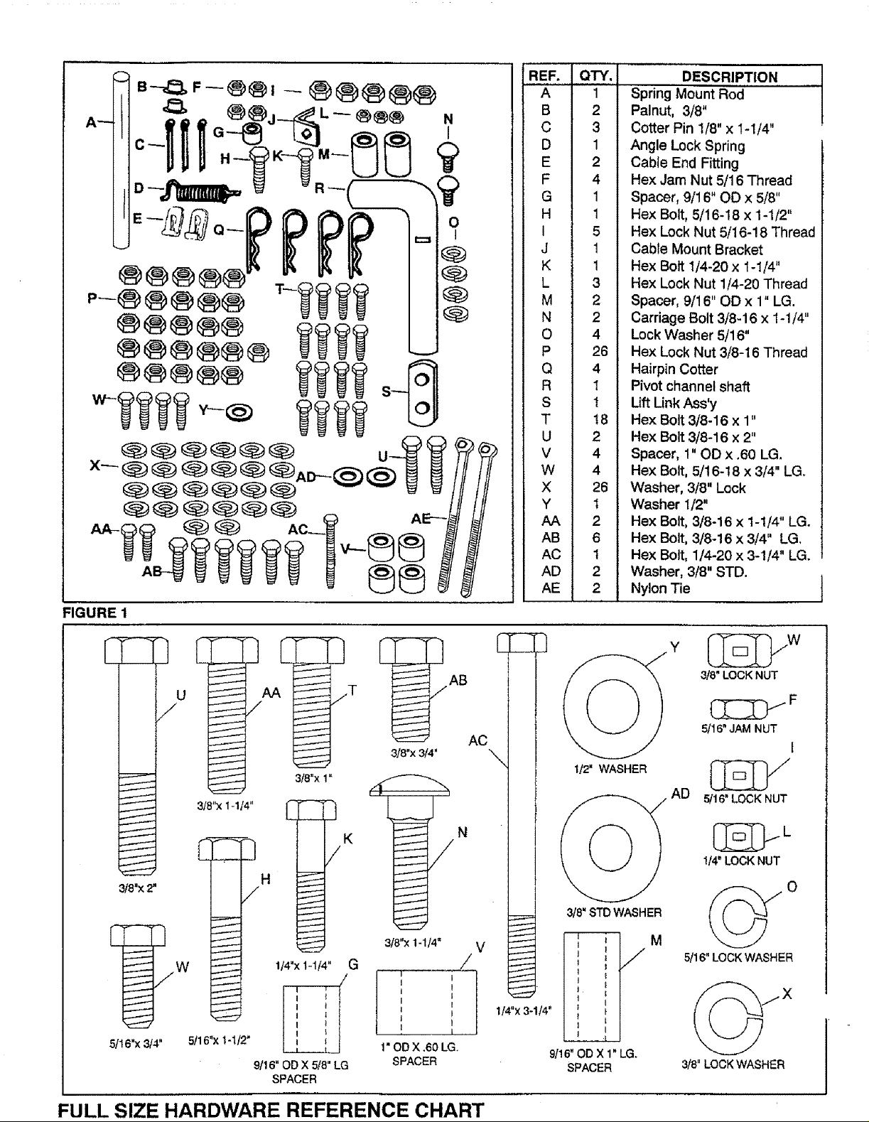
FIGURE 1
REF. QTY.
A 1
B 2
C 3
D 1
E 2
F 4
G 1
H 1
I 5
J 1
K 1
L 3
M 2
N 2
O 4
P 26
Q 4
R 1
S 1
T 18
U 2
V 4
W 4
X 26
Y I
AA 2
AB 6
AC 1
AD 2
AE 2
DESCRIPTION
Spring Mount Rod'......
Palnut, 3/8"
Cotter Pin 1/8" x I-1/4"
Angle Lock Spring
Cable End Fitting
Hex Jam Nut 5/16 Thread
Spacer, 9/16" OO x 5/8"
Hex Bolt, 5/16-18 x 1-1/2"
Hex Lock Nut 5/16-!8 Thread
Cable Mount Bracket
Hex Bolt 1/4-20 x 1-1/4"
Hex Lock Nut 1/4-20 Thread
Spacer, 9/16" OD x 1" LG.
Carriage Bolt 3/8-16 x 1-!/4"
Lock Washer 5/16"
Hex Lock Nut 3/8-16 Thread
Hairpin Cotter
Pivot channel shaft
Lift LinkAss'y
Hex Bolt3/8-16 x 1"
Hex Bolt3/8-16 x 2"
Spacer, 1" OD x .60 LG.
Hex Bolt, 5/16-18 x 3/4" LG.
Washer, 3/8" Lock
Washer 1/2"
Hex Bolt, 3/8-16 x 1-1/4" LG.
Hex Bolt, 3/8-16 x 3/4" LG.
Hex Bolt, 1/4-20 x 3-1/4" LG.
Washer, 3/8" STD.
Nylon Tie
3/8"X 2"
5/16"x3/4"
318"x1-114"
f
I
J
I
I
I
I
I
I
I
f
L
5tl 6"x I-1t2"
• jT
3/8"x 1_
H
/
114"x 1-1f4" G
9116" OD X 5/8" LG
SPACER
r- 3
W
3/8" LOCK NUT
/
] AB
AC
3/8"x3t4"
_ N
I12" WASHER
/
3/8' STDWASHER
318"x1-114= V
/
, J
I
! 1
i t
I I ,,,
1" OD X ,60 LG.
SPACER
114"x3-1/4" .
=
• . j/
9/16" OD X 1" LG.
SPACER
M
5/16" JAM NUT
[
5tl 6' LOCK NUT
1t4" LOCK NUT
O
5/16" LOCK WASHER
318"LOCK WASHER
FULL SIZE HARDWARE REFERENCE CHART
ASSEMBLY INSTRUCTIONS
TOOLS REQUIRED FOR ASSEMBLY
(1)
(1)
(1)
(1)
(1)
(1)
REMOVAL OF PARTS FROM CARTON
• Refer to carton contents figure on page 3 andfigure I on
NOTE: Right hand (R.H.) and left hand (L.H.) are deter-
TRACTOR PREPARATION
• Remove mower deck or any other attachment you may
ASSEMBLY OF SNOW BLADE TO
SERIES 917... TRACTORS
FOR ASSEMBLY OF SNOW BLADE TO SERIES 502...
TRACTORS GO DIRECTLY TO PAGE 6
FOR ASSEMBLY OF SNOW BLADE TO SERIES 536...
TRACTORS GO DIRECTLY TO PAGE 8
Pliers
Hammer
Adjustable Wrench (or socket set)
9/16" Open End or Box Wrench
7/16" Open End or Box Wrench
1/2" Open End or Box Wrench
page 4 for parts and hardware needed to assemble
snow blade.
mined from operators position while seated inthe
tractor.
have mounted to your tractor. Mark all loose parts and
save for re-assembly. Refer to owners manual for
removal of mower/attachment.
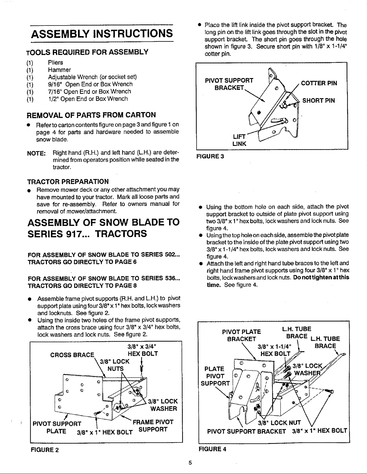
• PIace the lift link inside the pivot support bracket. The
long pin on the lift link goes through the slot in the pivot
support bracket. The short pin goes through the hole
shown in figure 3. Secure short pin with 1/8" x 1-1/4"
cotter pin.
PIVOT SUPPORT COTTER PIN
BRACKET
SHORT PIN
LIFT _ "J
LINK
FIGURE 3
• Using the bottom hole on each side, attach the pivot
support bracket to outside of plate pivot support using
two 3/8" x 1" hex bolts, lock washers and lock nuts. See
figure 4.
• Using the top hole on each side, assemble the pivot plate
bracket to the insideof the plate pivot support using two
3/8" x 1-1/4" hex bolts, lock washers and lock nuts. See
figure 4.
• Attach the left and right hand tube braces to the leftand
right hand frame pivot supports using four 3/8" x 1" hex
belts, Iockwashers and lock nuts. Do not tighten at this
time. See figure 4.
• Assemble frame pivot supports (R.H. and L.H.) to pivot
support plate using four 3/8" x 1" hex bolts, lock washers
and locknuts. See figure 2.
• Using the inside two holes of the frame pivot supports,
attach the cross brace using four 3/8" x 3/4" hex bolts,
lock washers and lock nuts. See figure 2.
3/8" x 3/4"
CROSS BRACE HEX BOLT
_\3/8" LOCK
le W_ e. &3/8. LOCK
L_ =,'_ I_ WASHER
PIVOT SU4ORT__JF "_ FRAME PIVOT
PLATE 3/8" x 1" HEX BOLT SUPPORT
FIGURE 2
PIVOT PLATE L.H. TUBE
BRACKET BRACE L.H. TUBE
3/8" x 1-1/4" BRACE
HEX BOLT
PLATE
PIVOT
3/8" LOCK NUT
PIVOT SUPPORT BRACKET 3/8" x 1" HEX BOLT
FIGURE 4
 Loading...