

Craftsman 486244031 Owner’s Manual
owners
manual
Model No.
486.244031
42"
SNOW BLADE
CAUTION:
Read Rules for
Safe Operation
and Instructions
Carefully
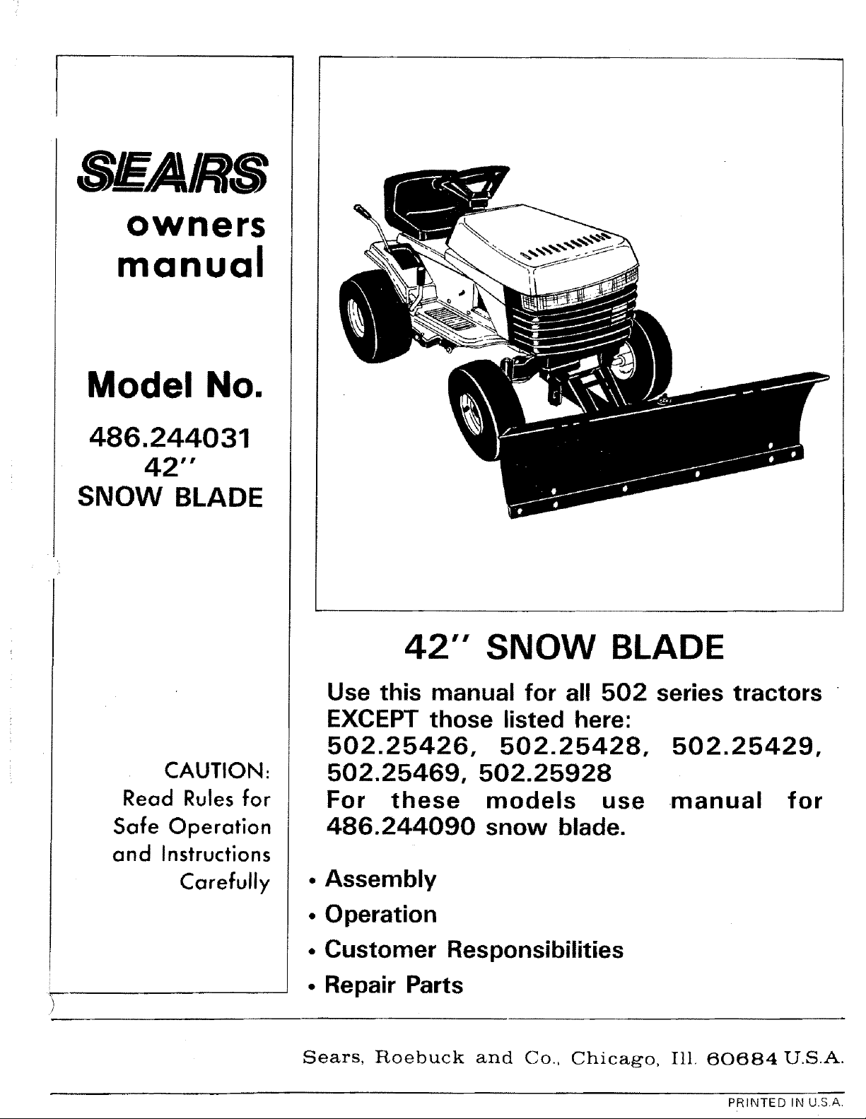
42'" SNOW BLADE
Use this manual for all 502 series tractors
EXCEPT those listed here:
502.25426, 502.25428,
502.25469, 502.25928
For these models use
486.244090 snow blade.
• Assembly
• Operation
• Customer Responsibilities
• Repair Parts
Sears, Roebuck and Co., Chicago, Ill. 60684 U.S.A.
502.25429,
manual for
PRINTED IN U.S.A,
RULES FOR SAFE OPERATIONS
Any power equipment can cause injury if operated improperly or if the user does not understand how to operate
the equipment.
LOOK FOR THIS SYMBOL TO POINT OUT
IMPORTANT SAFETY PRECAUTIONS. IT
MEANS ,. ATTENTION! BECOME ALERT!
YOUR SAFETY IS INVOLVED.
Exercise caution at all times, when using power equipment.
1. Read the tractor and snow blade owners manuals and know how to operate your tractor, before using tractor
with snow blade attachment.
2. Never operate tractor and snow blade without wearing proper clothing suited to weather conditions and
operation of controls.
3. Never allow children to operate tractor and snow blade, and do not allow adults to operate without proper
instructions.
4. Always begin with transmission in first (tow) gear and gradually increase speed as required.
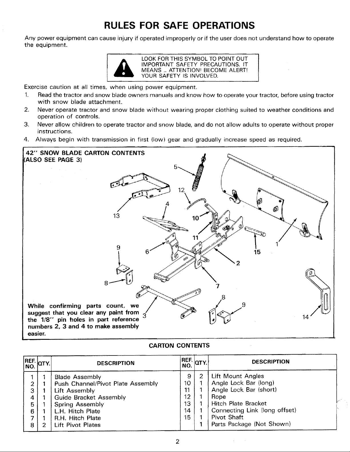
42" SNOW BLADE CARTON CONTENTS
ALSO SEE PAGE 3)
12
13
While confirming parts count, we
suggest that you clear any paint from
the 1/8" pin holes in part reference
numbers 2, 3 and 4 to make assembly
easier.
REE QTY.
NO.
1 1
2 1
3 1
4 1
5 1
6 1
7 1
8 2
Blade Assembly
Push Channel/Pivot Plate Assembly
Lift Assembly
Guide Bracket Assembly
Spring Assembly
L.H. Hitch Plate
R.H. Hitch Plate
Lift Pivot Plates
DESCRIPTION
CARTON CONTENTS
REF. QTY. DESCRIPTION
NO.
9 2 Lift Mount Angles
10 1 Angle Lock Bar (long)
11 1 Angle Lock Bar (short)
12 1 Rope
13 1 Hitch Plate Bracket
14 1 Connecting Link [long offset)
15 1 Pivot Shaft
1 Parts Package (Not Shown)
15
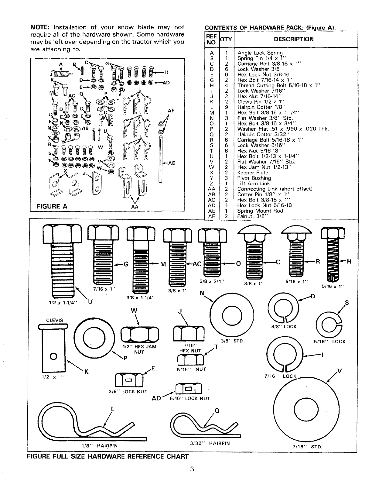
NOTE: Installation of your snow blade may not
require all of the hardware shown. Some hardware
may be left over depending on the tractor which you
are attaching to,
CONTENTS OF HARDWARE PACK: (Figure A}.
REF. QTY. DESCRIPTION
NO.
A 1 Angle Lock Spring
B 1 Spring Pin 1/4 x 1"
C 2 Carriage Bo{t 3/8-16 x !"
D 6 Lock 'Washer 3/8
E 6 Hex Lock Nut 3/8-16
G 2 Hex Bolt 7/16-14 x 1"
H 4 Thread Cutting Bolt 5/16-18 x 1"
I 2 Lock Washer 7/16"
J 2 Hex Nut 7/16-14"
K 2 Clevis Pin t/2 z 1"
L 9 Hairpin Cotter 1/8"
M 1 Hex Bolt 3/8-16 x 1-1/4"
N 3 Flat Washer 3/8" Std.
O 1 Hex Bolt 3/8-16 x 3/4"
P 2 Washer, Flat 31 x .990 x .020 Thk.
Q 2 Hairpin Cotter 3/32"
R 6 Carriage Bolt 5/16-18 x 1"
S 6 Lock Washer 5/16"
T 6 Hex Nut 5/16 18"
U 1 He× Bolt 1/2-13 x 1-1/4"
V 2 Flat Washer 7/16" Std.
W 2 Hex Jam Nut 1/2-13"
X 2 Keeper Plate
Y 3 Pivot Bushing
Z 1 Lift Arm Link
AA 2 Connecting Link (short offset)
AB 2 Cotter Pin 1/8" x 1"
AC 2 Hex Bolt 3/8-16 x 1"
AD 4 Hex Lock Nut 5/16-18
AE 1 Spring Mount Rod
AF 2 Palnut, 3/8"
CLEVIS
1/2 x 1"
H
3/8 x 1-1/4"
3/8 x 3/4"
3!8 x 1" N
3/8 x 1" 5/16 x 1"
5/16 x 1"
W
3/8"" STD
_-_ i" LOCK
K
._._E 5/16" NUT
318"
7/1 "
v
LOCKNUT AD 1[ l_-LJu"/5/1_ T
I
1/8- HAIRPIN
FIGURE FULL SIZE HARDWARE REFERENCE CHART
3/32" HAIRPIN
3
7/16" STD.
ASSEMBLY INSTRUCTIONS
TOOLS REQUIRED FOR ASSEIVIBLY
(1) Pliers
(1) Hammer
(1) Screwdriver
(1) 1/2" Open End or Box Wrench
(1) 9/16" Open End or Box Wrench
(1) 5/8" Open End or Box Wrench
(1) 3/4" Open End or Box Wrench
(1) Adjustable Wrench
Refer to carton contents figure on page 2 and figure
A on page 3 of snow blade supplement for parts and
hardware needed to assemble snow blade.
NOTE
RIGHT HAND (R.H.) AND LEFT HAND
(L.H.) ARE DETERMINED FROM
OPERATOR'S POSITION WHILE
SEATED ON TRACTOR.
.
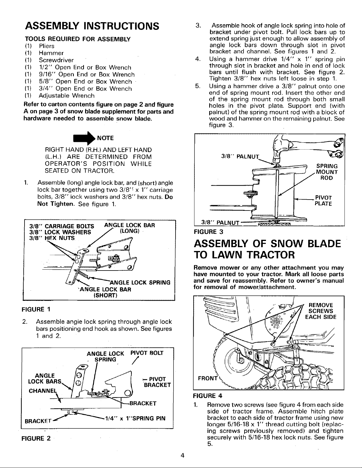
Assemble (long) angle lock bar, and (short) angle
lock bar together using two 3/8" x 1" carriage
bolts, 3/8" lock washers and 3/8" hex nuts. Do
Not Tighten. See figure 1.
3. Assemble hook of angle lock spring into hole of
bracket under pivot bolt. Pull lock bars up to
extend spring just enough to allow assembly of
angle lock bars down through slot in pivot
bracket and channel. See figures 1 and 2.
4. Using a hammer drive 1/4" x 1" spring pin
through slot in bracket and hole in end of lock
bars until flush with bracket. See figure 2.
Tighten 3/8" hex nuts left loose in step 1.
5. Using a hammer drive a 3/8" palnut onto one
end of spring mount rod. Insert the other end
of the spring mount rod through both small
holes in the pivot plate. Support end (with
palnut) of the spring mount rod with a block of
wood and hammer on the remaining palnut. See
figure 3.
3/8" PALNUT _l
SPRING
MOUNT
ROD
__ IVOT
PLATE
3/8"" CARRIAGE BOLTS ANGLE LOCK BAR
33188::'°cKWASHERS/ (LONG)
•
'ANGLE LOCK BAR
ISHORT)
FIGURE 1
2. Assemble angle lock spring through angle lock
bars positioning end hook as shown. See figures
1 and 2.
ANGLE LOCK PIVOT BOLT
SPRING /
ANGLE
LOCK BARS _- PIVOT
CHANNEL
BRACKET--1/4" x 1"SPRING PIN
FIGURE 2
'BRACKET
3/8'" PALNU"
FIGURE 3
ASSEMBLY OF SNOW BLADE
TO LAWN TRACTOR
Remove mower or any other attachment you may
have mounted to your tractor. Mark all loose parts
and save for reassembly. Refer to owner's manual
for removal of mower/attachment.
REMOVE
SCREWS
FIGURE 4
Remove two screws (see figure 4 from each side
side of tractor frame. Assemble hitch plate
bracket to each side of tractor frame using new
longer 5/16-18 x 1" thread cutting bolt (replac-
ing screws previously removed) and tighten
securely with 5/16-18 hex lock nuts. See figure
5.
4
!
5/16" x 1" THREAD
CUTTING SCREW
WITH 5/16" HEX
/_ LOCK NUT ON INSIDE
'_OF TRACTOR FRAME
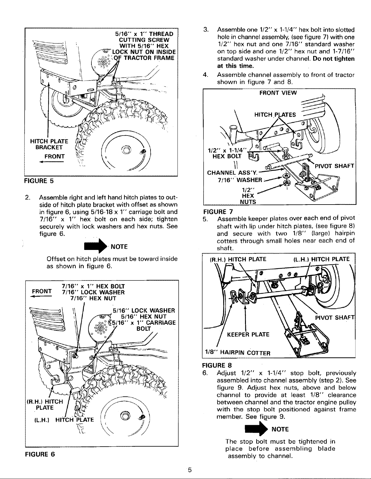
3. Assemble one 1/2" x 1-1/4 °' hex bolt into slotted
hole in channel assembly, (see figure 7) with one
1/2" hex nut and one 7/16" standard washer
on top side and one 1/2" hex nut and 1-7/16"
standard washer under channel. Do not tighten
at this time.
4. Assemble channel assembly to front of tractor
shown in figure 7 and 8.
FRONT VIEW
HITCH
HITCH PLATE
BRACKET
FRONT
FIGURE 5
.
Assemble right and left hand hitch plates to out-
side of hitch plate bracket with offset as shown
in figure 6, using 5/16-18 x 1" carriage bolt and
7/16" x 1" hex bolt on each side; tighten
securely with lock washers and hex nuts. See
figure 6.
\T
NOTE
Offset on hitch plates must be toward inside
as shown in figure 6.
FRONT 7/16" LOCK WASHER
"*_ 7/16" HEX NUT
7/16" x 1" HEX BOLT
5/16" LOCK WASHER
oo°I
5/16" x 1" CARRIAGE
oo %
y BOLT
5/16" HEX NUT
\
1/2" x 1-1/4"
HEX BOLT
CHANNEL ASS'Y.
7/16"-WASHER
1/2"
HEX
NUTS
FIGURE 7
5.
Assemble keeper plates over each end of pivot
shaft with lip under hitch plates, (see figure 8)
and secure with two 1/8" (large) hairpin
cotters through small holes near each end of
shaft.
(R.H.) HITCH PLATE (L.H.) HITCH PLATE
KEEPER PLATE
SHAFT
(R.H.) HITCH
PLATE
IL.H.) HITCH PLATE
FIGURE 6
1/8" HAIRPIN COTTER
FIGURE 8
6. Adjust 1/2" x 1-1/4" stop bolt, previously
assembled into channel assembly (step 2). See
figure 9. Adjust hex nuts, above and below
channel to provide at least !/8" clearance
between channel and the tractor engine pulley
with the stop bolt positioned against frame
member. See figure 9.
_NOTE
The stop bolt must be tightened in
place before assembling blade
assembly to channel.
5
 Loading...