

Page 1
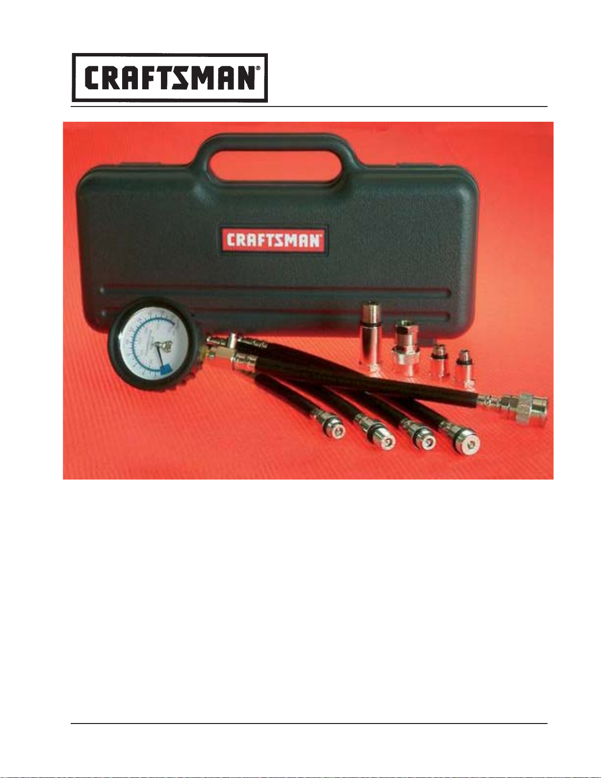
MODEL 47089
COMPRESSION TEST KIT
JAN - 04 Section
Form 823451
- MV19
Page
- 1
Page 2
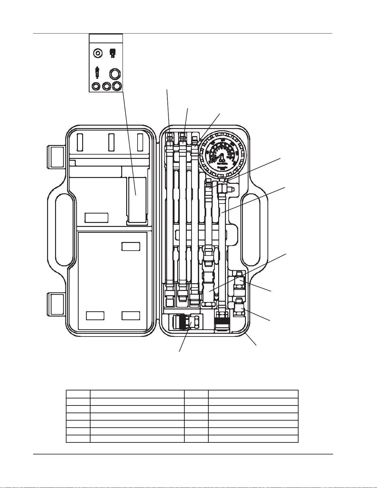
823437
Hose 14MM Long Reach
823441
Field Service Kit
823436
Hose 14MM Short Reach
823438
Hose 18 MM Short Reach
823435
Hose 14MM
Short Reach
823449
Gauge, Valve
and Hose
823433
14MM - 18MM
Adapter
Part No. D es cripti on Part No. D es cripti on
823431 10MM Adapt er 823438 Hose Long reach 18MM x 11.625
823432 12MM Adapt er 823440 Pressure Hold Adapter
823433 14MM Female - 18MM M a le Adapt er 823441 Field S er vice Kit
823435 Hose Short R eac h 14 MM x 6.05 823442 Case
823436 Hose Short R eac h 14 MM x 11.625 823448* Gauge
823437 Hose Long Reach 14MM x 11.951 823449 Gaug e Assembly
Page Number - 2
* Not Shown
823440
Pressure Hold Adapter
823431
10MM Adapter
823432
12 MM Adapter
823442
Plastic Case
Form 823451
Page 3

Always read instructions carefully prior to use.
Dry Compression Test Procedures:
Included in this Kit
• Heavy duty 2 ¾” (70 mm) gauge with high impact lens,
rubber boot, and three (3) scales of measure (psi, kg/cm
bar), attached to 10" (250 mm) hose and quick release
coupler
• Four (4) extension hoses:
• 6 ½” (165 mm) long x 14 mm thread, short
• 12" (305 mm) long x 14 mm thread, short
• 12" (305 mm) long x 14 mm thread, long
• 12" (305 mm) long x 18 mm thread, short
• One (1) adapter: 14 mm thread, short x 18 mm thread, long
• Two (2) small engine adapters
• 10 mm thread
• 12 mm thread
• One (1) quick release air hold adapter
• Custom blow-molded case
• Field service kit
2
,
Applications
The Craftsman Professional Compression Test Kit can perform
dry or wet compression tests to determine the amount of
pressure produced in the cylinder of an engine. It can also be
used as a tool for pressurizing an engine cylinder to hold the
valves closed while performing repairs.
How to Perform a Comression Test
Precautions & Diagnostic Notes:
WARNING: DO NOT use the ignition switch during the
compression test on fuel-injected vehicles. Use of a
remote starter switch to crank the engine is recommended. Fuel injectors on many late model vehicles
are triggered by the ignition switch during the cranking
mode, this could result in a fire hazard or contamination
of the engine’s oil with fuel.
Always use eye protection when performing compression tests.
An engine in good operating condition will produce a certain
amount of pressure in each cylinder. Normally, the cylinders
should be within 10 percentage points of one another and
within the manufacturer’s specifications. The pressure should
rise smoothly on each stroke of the engine, until it reaches a
peak.
If the pressure reading fails to rise, or it remains the same for
several strokes of the engine and begins to rise, the likely
cause of the problem is a sticking valve.
If two adjacent cylinders show pressure readings of 20 or
more pounds below the other cylinder readings, suspect a
blown head gasket.
If a cylinder shows a pressure reading of 15 or more pounds
higher than the other cylinders, the probable cause is carbon
build-up inside the cylinder.
The Craftsman Professional Compression Test Kit can perform
two tests: the dry compression test and the wet compression
test. The result of performing these tests will provide an
indication of the condition of the piston rings, the cylinders, and
valve-train.
1. Refer to the appropriate service manual for the compression
specifications specific to the engine you are testing.
2. Start engine and allow engine to run until it reaches normal
operating temperature (usually about 15 minutes.) Turn
engine OFF .
3. Install an auxiliary starter switch in the starting circuit.
4. While wearing eye protection, use compressed air to
carefully remove dirt and debris from the area around the
spark plugs.
5. Remove spark plugs one at a time, marking the number of
the cylinder they were removed from, and place them on a
clean flat surface. This will aid you in identifying problem
cylinders by allowing the comparison of spark plug appearance to the compression level of a given cylinder.
NOTE: When testing engines with two spark plugs per
cylinder, it is only necessary to remove the spark
plugs located on the exhaust side.
6. On vehicles with standard distributors, disconnect the coil
wire (high tension lead) from the distributor cap and secure
it to a suitable ground, or disable the ignition by disconnecting the positive (BAT) terminal from the ignition coil.
7. On vehicles with a distributorless ignition (DIS), disable the
ignition system by removing the electronic ignition (control)
module fuse, or disconnect the crank angle sensor.
NOTE: Refer to the appropriate service manual to
determine which fuse or component to temporarily
remove or disconnect.
8. Remove air cleaner from carburetor or throttle body and
secure throttle linkage in wide-open throttle (WOT) position.
NOTE: NEVER place anything inside the throttle body;
internal damage to the engine could result. On
vehicles equipped with port fuel injection, remove
throttle linkage covers (as necessary) and secure
throttle linkage in the wide-open throttle (WOT)
position.
9. Crank engine several times to ensure removal of any foreign
matter that may have fallen into the cylinders during preparation for test.
10. Select the appropriate adapter fitting (14mm, 18mm short
reach or 14mm, 18mm long-reach), and thread adapter into
spark plug hole of cylinder head.
11. Connect the appropriate test hose or adapter to the gauge
assembly.
12. Crank the engine at least five compression strokes or until
the pressure reading stops increasing on gauge.
13. Read the pressure level on the gauge and record the
reading along with the cylinder number being tested.
Example: #1-150 psi, #2-145 psi, etc.
14. Repeat this test on each cylinder. If any of the cylinder
readings are found to be low or uneven, perform wet
compression test.
Form 823451
Page Number - 3
Page 4

15. When compression test is complete, return the spark plugs
to their respective cylinders and the throttle and ignition
components to their normal positions.
Wet Compression Test Procedure
CAUTION: DO NOT perform the wet compression test on
any diesel engine. The higher compression in a diesel
engine may cause engine damage or injury to the
technician.
The wet compression is a way to remove the influence of the
piston rings, pistons and cylinders from the compression test.
After completing the dry compression test, squirt approximately
one teaspoon of engine oil into the spark plug holes and crank
the engine several times to seal the piston rings. Repeat the dry
compression test outlined above. NOTE: If the readings during
the wet compression test are greater, then air is leaking around
worn or damaged piston rings. If the reading is approximately
the same for both wet and dry tests then the valves, valve lifters
or the camshaft lobes are worn. Any low reading of cylinder
compression indicates worn or damaged parts.
Small Engine Compression Testing
The Craftsman Professional Compression Test Kit has two (2)
adapters, 10mm and 12mm, that allow it to be used on small
engines found in lawn mowers, chain saws and line trimmers.
To use these adapters:
5. Attach the Air Hold Adapter to the extension hose.
6. Attach a shop air hose to the Air Hold Adapter, this will
maintain air pressure in the cylinder to hold the valves
closed while performing repairs. (It may be necessary to
rotate the engine until all valve are closed and air is holding
in the cylinder)
Note: The air hold quick connector does not come with
a compressed air line fitting to adapt to your air source.
This will have to be purchased separately to fit your
system.
For answers to technical questions, or to
order replacement parts, call or fax:
Phone: (314) 679-4200 Ext. 4782
Fax: (314) 679-HELP (4357)
Full One Year Warranty
If this Craftsman® Compression Test Kit is defective in material or
workmanship within one (1) year from the date of purchase,
return it to your nearest Sears store in the United States, and it will
be replaced free of charge.
Sear, Roebuck and Co., Dept. 817WA,
Hoffman Estates, IL 60179
1. Disconnect the spark plug wire and remove the spark plug.
2. Thread the appropriate size adapter onto the compression
tester main hose end until the o-ring seats (do not use a
wrench to tighten).
3. Thread the assembly into the cylinder spark plug hole until
the o-ring on the adapter seats firmly (do not use a wrench
to tighten).
4. Ensure the spark plug is grounded to the cylinder head or is
insulated in a way that will prevent an electric shock
hazard.
5. Crank the engine over using the pull cord (or starter if
electric) a minimum of 5 revolutions. This will allow the
cylinder to build sufficient compression to be measured.
6. Refer to the manufacturer’s data to determine the correct
reading
Using the Pressure Hold Adapter
The Craftsman Professional Compression Tester comes with a
pressure hold adapter. This adapter is used to perform valve
seal replacement on an engine without removing the cylinder
head(s). To use the adapter:
1. Remove the spark plug from the desired cylinder.
2. Select the appropriate extension hose that will fit the spark
plug hole.
TO A VOID PERSONAL INJURY AND/OR VEHICLE
DAMAGE:
While some precautions are specified in this manual, and
should be noted to avoid personal injury or vehicle damage,
it is not possible for these cautions to cover all conceivable
ways in which service or testing might be done, or all
possible hazardous consequences of each way, nor could
Lincoln possibly know or investigate all such ways. It is
therefore the responsibility of anyone using this manual or
any other Mityvac product, to satisfy him or herself
completely that neither personal safety nor vehicle safety
will be jeopardized by the service methods selected. Any
such injury or damage is entirely the user’s responsibility.
This device is not to be used in any manner on the human
body.
3. Using the valve core tool (from the field service kit included),
remove the valve core from the end of the hose and lay it
aside.
4. Thread the extension hose into the spark plug hole until the
o-ring seats; do not use pliers or a wrench to tighten.
Page Number - 4
Form 823451
Page 5

TEST DE COMPRESSION PROFESSIONNEL
P/N 05530
Prenez soin de toujours lire les instructions avant
utilisation.
Descriptif Général
Le Testeur de Compression Professionnel Craftsman mesure
le niveau de pression qu’un cylindre de moteur peut produire. La
face frontale de la jauge du testeur possède trois échelles de
mesure : livre par pouce carré (psi), bar et kilogramme par
centimètre carré (kg/cm).
Pour tester le niveau de compression d’un cylindre donné,
enfiler le tuyau du test de compression approprié dans la fente
de la bougie d’allumage du cylindre à tester.
Le Test de Compression Professionnel Craftsman peut être
utilisé pour le test de compression sèche et le test de compression mouillée. Les résultats de ces tests donneront une
indication sur l’état des anneaux du piston, des cylindres, et de
la train de valve.
Remarques : Précautions et Diagnostic
AVERTISSEMENT : NE PAS utiliser l’interrupteur pendant
le test de compression sur des véhicules à injection de
combustible. L’utilisation d’un démarreur télécommandé pour mettre le moteur en marche est recommandé. Les systèmes d’injection de carburant sur de
nombreux modèles récents sont déclenchés par
l’interrupteur pendant la mise en marche, cela peut
provoquer un incendie ou la contamination de l’huile
moteur par du carburant.
Prenez soin de toujours utiliser une protection pour les
yeux lorsque vous faites des tests de compression.
Un moteur en bon état de fonctionnement produira un certain
niveau de pression sur chaque cylindre. Normalement, les
cylindres doivent rester dans une fourchette de dix points (pour
cent) l’un de l’autre, et respecter les caractéristiques du
fabricant. La pression doit augmenter doucement à chaque
sursaut du moteur, jusqu’à ce qu’elle atteigne un pic.
Si la pression ne parvient pas à monter, ou si elle reste la même
après plusieurs sursauts du moteur puis augmente, la cause du
problème est probablement une valve collante.
Si, sur deux cylindres adjacents, l’un montre un niveau de
pression de 20 livres ou plus de moins que l’autre, on peut
suspecter une tête de garniture cassée.
Si un cylindre montre une pression supérieure de 15 livres ou
plus aux autres cylindres, c’est qu’il y a certainement un amas
de carbone dans le cylindre.
Procédures pour le Test de Compression
Sèche :
1. Se reporter au manuel d’entretien approprié pour les
caractéristiques de compression spécifiques au moteur que
vous testez.
2. Démarrez le moteur et laissez lui le temps d’atteindre une
température normale de fonctionnement (environ 15 minutes
habituellement). Arrêtez le moteur.
3. Installez un interrupteur de starter auxiliaire dans le circuit
de démarrage.
4. En gardant toujours vos protections oculaires, utilisez de l’air
comprimé pour évacuer avec soin poussière et débris de la
zone environnante des bougies d’allumage.
5. Retirez les bougies une après l’autre, en notant le numéro
de cylindre duquel chaque bougie a été retirée, et disposezles sur une surface plane et propre. Cela vous aidera à
identifier les cylindres à problème en vous permettant de
comparer l’aspect de la bougie au niveau de compression
d’un cylindre donné.
À NOTER : En testant les moteurs à deux bougies par
cylindre, il n’est nécessaire d’enlever que les bougies
situées du côté de l’échappement.
6. Sur les véhicules à distributeur standard, branchez la
bobine (tête haute tension) du capot du distributeur et
mettez-la en sureté sur une surface adaptée ou bien
désactivez l’allumage en débranchant le terminal positif
(BAT) de la bobine d’allumage.
7. Sur les véhicules à allumage sans distributeur (DIS),
désactivez le système d’allumage en ôtant le fusible
d’allumage électronique (commande) ou désactivez le
capteur d’angle de mise en marche.
À NOTER : Se reporter au manuel d’entretien approprié pour
savoir quel fusible ou composant ôter ou déconnecter de
façon temporaire.
8. Ôtez le filtre à air du carburateur ou le corps du régulateur
et placez le lien du régulateur en position régulateur grand
ouvert (WOT).
À NOTER : NE JAMAIS placer quoique ce soit dans le
corps du régulateur ; le moteur pourrait subir des
dégâts internes. Sur les véhicules équipés
d’injection gauche de carburant, ôtez les couvercles
de liens du régulateur (si nécessaire) et placez le
lien du régulateur en position régulateur grand
ouvert (WOT).
9. Mettre en marche le moteur plusieurs fois pour s’assurer
que tout corps étranger qui serait tombé dans les cylindres
pendant la préparation du test ait été évacué.
10. Sélectionnez la taille de l’adaptateur (14mm, 18mm extension
courte ou 14mm, 18mm extension longue, et faire passer
l’adaptateur dans le trou de la bougie de la tête de cylindre.
11. Branchez le tuyau de test approprié ou l’adaptateur à la
jauge.
12. Faire faire au moteur au moins cinq coups de compressions
ou jusqu’à ce que la pression cesse d’augmenter sur la
jauge.
13. Lire le niveau de pression sur la jauge et enregistrez cette
lecture ainsi que le numéro de cylindre testé. Exemple : #1-
150 psi, #2-145 psi, etc.
14. Répétez ce test sur chaque cylindre, si les résultats
constatés sur les cylindres semblent bas ou irréguliers,
faites le test de compression mouillée.
15. Lorsque le test de compression est terminé, replacez les
bougies sur leur cylindre respectif, remettez le régulateur et
les composants de l’allumage en position normale.
Form 823451
Page Number - 5
Page 6

Procédures pour le Test de Compression
Mouillée
(Il pet s’avérer nécessaire de faire tourner le moteur jusqu’à
ce que toutes les soupapes soient fermées et que l’air soit
maintenu dans le cylindre).
ATTENTION : NE PAS faire de test de compression
mouillée sur les moteurs diesel. La compression plus
élevée sur un moteur diesel peut causer des dégâts au
niveau du moteur ou des blessures pour le mécanicien.
La compression mouillée permet d’enlever l’influence des
anneaux de piston, des pistons et cylindres du test de compression. Après avoir terminé le test de compression sèche,
verser environ une cuillère à café d’huile de moteur dans les
fentes de bougies et faire démarrer le moteur plusieurs fois
pour sceller les anneaux de pistons. Répétez les étapes du test
de compression sèche mentionnées ci-dessus.
À NOTER : Si les résultats pendant le test de compression
mouillée sont plus élevés, c’est que de l’air fuit autour des
anneaux de pistons usés ou endommagés. Si les résultats
sont à peu près les mêmes pour les deux tests, c’est que les
valves, les valves poussoirs ou l’arbre à cames sont usés.
Tout résultat faible au niveau du cylindre de compression
indique que des pièces sont usées ou endommagées.
Test de Compression d’un Petit Moteur
Le Testeur de Compression Professionnel Craftsman possède
deux (2) adaptateurs, 10mm et 12mm qui permettent de l’utiliser
sur des petits moteurs tels que ceux des tondeuses, des
tronçonneuses et des outils de taille. Pour utiliser ces adaptateurs :
1. Débranchez le câble de la bougie et ôtez la bougie.
2. Placez l’adaptateur de taille appropriée à l’extrémité du tube
principal du testeur de compression jusqu’à ce que l’anneau
se place (ne pas utiliser de clé pour serrer).
3. Faites le passer dans la fente de bougie du cylindre jusqu’à
ce que l’anneau de l’adaptateur se place et tienne fermement
(ne pas utiliser de clé pour serrer).
4. Vérifiez que la bougie soit fixée à la tête de cylindre ou soit
isolée de façon à éviter tout danger de choc électrique.
5. Démarrez le moteur en utilisant la courroie de démarrage (ou
le starter si c’est électrique) en attendant au moins le temps
de 5 révolutions. Cela permettra au cylindre de créer
suffisamment de compression à mesurer.
6. Se reporter aux données du fabricant pour connaître les
résultats corrects à obtenir.
Utilisation de l’Adaptateur de Maintien de
Pression
À NOTER : Le connecteur rapide Air Hold n’est pas
livré avec un tube à air comprimé à adapter à votre
source d’air. Il devra être acheté séparément pour
s’adapter à votre système.
Pièces
• Jauge de 2 ¾’’ à grand rendement avec lentille à haut
impact, boot en caoutchouc et trois échelles de mesure
différentes : PSI, kg/cm² et Bar, un tube fouet fixe de 10’’ et
un Quick Coupler pour une installation rapide.
• Une soupape de décompression montée sur le cou de la
jauge pour un accès facile.
• Quatre tubes d’extension : 6 1/2’’ 14mm extenseur court,
12’’14mm extenseur court, 12’’14mm extenseur long et
12’’18mm extenseur court
• Un adaptateur d’extenseur long 14mm femelle x 18mm male
• Deux adaptateurs pour petit moteur : 12mm et 10mm
• Un adaptateur de maintien d’air à évacuation rapide pour
l’entretien de joint de soupape sur véhicule
• Boîte moulée pour assurer protection et facilité de rangement
• Kit d’entretien de terrain, comprenant des joints, des
soupapes de Schrader et un outil d’enlèvement de noyau
utilisé pour maintenir votre kit.
Si vous avez des questions techniques ou si vous désirez
commander des pièces de rechange, appelez ou envoyez un
fax :
Téléphone : (314)679-4200
Fax : (314) 679-HELP (4357)
Garantie pendant Une Année Complète
Si ce Kit d’Essais à la Compression Craftsman® s’avère
défectueux, vice de matériau ou de fabrication durant une
période d’un (1) an après la date d’achat, retournez-le à votre
magasin Sears le plus proche (aux Etats Unis), et il sera
remplacé gratuitement.
Cette garantie vous donne des droits légaux précis. Il est
possible que vous ayez aussi d’autres droits, ceux-ci peuvent
différer d’un état à un autre.
Sears, Roebuck and Co., Département 817WA
Hoffman Estates, IL 60179
Le testeur de Compression Professionnel Craftsman est livré
avec un adaptateur de maintien de pression. Cet adaptateur est
utilisé lors du remplacement des joints de valves sur un moteur
sans enlever la ou les têtes de cylindre. Pour utiliser
l’adaptateur :
1. Ôtez la bougie du cylindre désiré.
2. Choisissez l’extenseur adéquat qui s’adaptera à la fente de
la bougie.
3. Otez el coeur de la poupape à l’extrémité du tuyau en
utilisant l’outil compris dans le kit d’entretien. Posez le de
côté.
4. Faites passer l’extenseur dans la fente de bougie jusqu’à ce
que l’anneau se place, ne pas utiliser de pinces ou de clé
pour serrer.
5. Fixez le connecteur rapide Air Hold à l’extenseur.
6. Fixez un tube de chambre à air à l’Adaptateur Air Hold, cela
maintiendra suffisamment d’air dans le cylindre pour
maintenir les soupapes fermées pendant les réparations.
Page Number - 6
POUR ÉVITER LES BLESSURES ET/OU LES
DÉGÂTS DE VÉHICULE :
Alors que certaines précautions sont spécifiées dans ce
manuel, et devraient être notées pour éviter les blessures
personnelles ou les dégâts de véhicule, il n’est pas possible
de couvrir toutes les possibilités d’utilisation d’entretien ou
de test, ou une éventuelle conséquence dangereuse de
ces possibilités ; Lincoln ne pourrait non plus connaître ou
enquêter sur ces possibilités. La responsabilité de
quiconque utilisant ce manuel ou tout autre produit Craftsman, est donc engagée pour son entière satisfaction,
sachant qu’aucune des méthodes d’utilisation sélectionnées
ne peut mettre en danger la sécurité des personnes ou des
véhicules. L’utilisateur est entièrement responsable de toute
blessure ou dommage. Cet appareil ne doit en aucun cas
être utilisé sur le corps humain.
Form 823451
Page 7

EQUIPO PROFESIONAL PARA PRUEBAS DE COMPRESIÓN
NÚMERO DE PARTE 05530
Siempre lea las instrucciones cuidadosamente antes de
usarlo.
Descripción General
El Probador de Compresión Profesional Craftsman mide cuanta
presión producirá un cilindro del motor. La carátula del probador
tiene tres escalas de medición: libras por pulgada cuadrada
(psi), bares y kilogramos por centímetro cuadrado (kg/cm2).
Al probar el nivel de compresión de un cilindro determinado,
atornille el conjunto apropiado de la manguera de prueba de
compresión en el agujero de la bujía de encendido del cilindro
que vaya a probarse.
El Equipo Profesional de Pruebas de Compresión Craftsman
puede hacer dos pruebas: la prueba de compresión en seco y
la prueba de compresión en condiciones húmedas. El resultado
de la ejecución de estas pruebas proporcionará una indicación
del estado de los anillos de los pistones, los cilindros y el tren
de válvulas.
Precauciones y Notas Diagnósticas:
ADVERTENCIA: NO use el interruptor de encendido
durante la prueba de compresión en los vehículos con
inyección de combustible. Se recomienda el uso de un
interruptor remoto del motor de arranque para hacer
girar el motor sin que arranque. Los inyectores de
combustible en muchos vehículos de modelo reciente
son activados por el interruptor de encendido durante
la modalidad de hacer girar el motor sin que arranque;
esto podría resultar en un riesgo de incendio o en la
contaminación del aceite del motor con combustible.
Siempre use protección para los ojos cuando haga
pruebas de compresión.
Un motor en buen estado de funcionamiento producirá cierta
cantidad de presión en cada cilindro. Por lo general, los cilindros
deben tener una diferencia de no más de 10 puntos porcentuales entre sí y estar dentro de las especificaciones del fabricante. La presión debe aumentar suavemente con cada carrera
de los pistones del motor, hasta que alcance un valor máximo.
Si la lectura de presión no aumenta o permanece igual durante
varias carreras de los pistones del motor y empieza a subir, la
causa probable del problema es una válvula pegada.
Si dos cilindros adyacentes muestran lecturas de presión de 20
o más libras debajo de las lecturas de los demás cilindros, se
debe sospechar que hay un empaque de la culata quemado.
Si un cilindro muestra una lectura de presión de 15 o más libras
más alta que los demás cilindros, la causa probable es la
acumulación de carbón dentro del cilindro.
Procedimientos de la Prueba de Compresión en Seco:
1. Consulte el manual de servicio apropiado para las especificaciones de compresión específicas del motor que esté
probando.
2. Arranque el motor y déjelo funcionar hasta que alcance la
temperatura normal de trabajo (por lo general alrededor de
15 minutos.) Apague el motor.
3. Instale un interruptor auxiliar de arranque en el circuito
correspondiente.
4. Utilizando algún tipo de protección para sus ojos, use aire
comprimido para eliminar cuidadosamente la suciedad y los
desechos del área alrededor de las bujías de encendido.
5. Quite las bujías de encendido una por una, marcando el
número del cilindro del que fueron quitadas y colóquelas
sobre una superficie plana limpia. Esto le ayudará a
identificar los cilindros problema al per-mitirle hacer una
comparación de la apariencia de la bujía de encendido con
el nivel de compresión de un cilindro determinado.
NOTA: Al probar motores con dos bujías de encendido por cilindro, sólo es necesario quitar las bujías de
encendido localizadas del lado del escape.
6. En los vehículos con distribuidores convencionales,
desconecte el cable de la bobina (el conductor de alta
tensión) de la tapa del distribuidor y fíjelo a una tierra
apropiada o inactive el encendido desconectando la terminal
positiva (BAT) de la bobina del sistema de encendido.
7. En los vehículos con un sistema de encendido sin distribuidor (DIS), inactive el sistema de encendido quitando el
fusible del módulo (de control) del encendido electrónico o
desconecte el sensor del ángulo del cigüeñal.
NOTA: Consulte el manual de servicio apropiado
para determinar cuál fusible o componente debe
quitarse o desconectarse temporalmente.
8. Quite el filtro de aire del carburador o el cuerpo del estrangulador y asegure el varillaje del estrangulador en la
posición del estrangulador totalmente abierto (ETA).
NOTA: NUNCA coloque alguna cosa dentro del cuerpo
del estrangulador pues esto podría resol-tar en
daños internos en el motor. En los vehículos equipados con inyección de combusti-ble en los puertos,
quite las cubiertas del varillaje del estrangulador
(según sea necesario) y asegure el varillaje del
estrangulador en la posición del estrangulador
totalmente abierto (ETA).
9. Haga girar el motor varias veces, sin arrancarlo, para
asegurar la eliminación de cualquier materia extraña que
pueda haber caído dentro de los cilindros durante la
preparación para la prueba.
10. Seleccione la conexión adaptadora apropiada (14 mm, 18
mm de corto alcance o 14 mm, 18 mm de largo alcance) y
atorníllela en el agujero de la bujía de encendido de la culata
de cilindros.
11. Conecte la manguera de prueba o la conexión adaptadora
apropiada al conjunto de la carátula del compresómetro.
12. Haga girar el motor, sin arrancarlo, por lo menos cinco
carreras de compresión o hasta que la lectura de presión
deje de aumentar en la carátula del compresómetro.
13. Lea el nivel de presión en el compresómetro y regístrela
junto con el número del cilindro que esté probando. Ejemp-
lo: #1150 psi, #2145 psi, etc.
14. Repita esta prueba en cada cilindro. Si se encuentra que
cualquiera de las lecturas de los cilindros es baja o
desigual, haga la prueba de compresión en condiciones
húmedas.
15. Cuando la prueba de compresión esté completa, vuelva a
colocar las bujías de encendido en sus respectivos cilindros
y vuelva a colocar los componentes del varillaje y el
encendido en sus posiciones normales.
Form 823451
Page Number - 7
Page 8

Procedimiento de la Prueba de Compresión
en Condiciones Húmedas
PRECAUCIÓN: NO haga la prueba de compresión en condiciones húmedas en ningún motor diesel. La mayor
compresión en un motor diesel puede causar daños al
motor o lesiones al técnico.
La compresión en condiciones húmedas es una manera de
eliminar la influencia de los anillos de los pistones, los pistones y
los cilindros de la prueba de compresión. Después de hacer la
prueba de compresión en seco, inyecte con la aceitera un chorro
de aproximadamente una cucharadita de aceite para motores en
los agujeros de las bujías de encendido y haga girar el motor
varias veces, sin arrancarlo, para sellar los anillos de los pistones. Repita los pasos de la prueba de compresión en seco
mencionados arriba. NOTA: Si las lecturas durante la prueba de
compresión en condiciones húmedas son mayores, entonces hay
escapes de aire alrededor de los anillos de los pistones gastados o dañados. Si la lectura es aproximadamente igual para las
pruebas en condiciones húmedas y las pruebas en seco,
entonces las válvulas, los levantaválvulas o los lóbulos del árbol
de levas están gastados. Cualquier lectura baja de compresión
de los cilindros indica partes gastadas o dañadas.
Pruebas de Compresión de Motores
Pequeños
El Probador de Compresión Profesional Craftsman tiene dos (2)
adaptadores, de 10 mm y 12 mm, que permiten usarlo en los
motores que se encuentran en las podadoras de césped, las
cadenas de motosierras y las recortadoras de cable. Para usar
estos adaptadores:
1. Desconecte el cable de la bujía de encendido y quite ésta.
2. Atornille el adaptador de tamaño apropiado en la manguera
principal del compresómetro hasta que asiente el anillo en “O”
(no use una llave para apretarlo).
3. Atorníllelo en el agujero de la bujía de encendido del cilindro
hasta que el anillo en “O” del adaptador se asiente firmemente
(no use una llave para apretarlo).
4. Asegúrese que la bujía de encendido esté conectada a tierra
con la culata del cilindro o que esté aislada de tal manera que
evite un riesgo de choque (toque) eléctrico.
5. Haga girar el motor utilizando el cordón de arranque (o el motor
de arranque si es eléctrico) un mínimo de 5 revoluciones. Esto
permitirá que el cilindro acumule una compresión suficiente
para que pueda medirse.
6. Consulte los datos del fabricante para determinar la lectura
correcta.
Como Usar el Adaptador de Retención de
Presión
El Probador de Compresión Profesional Craftsman viene con un
adaptador de retención de presión. Este
adaptador se usa cuando los sellos de las válvulas de un motor
son reemplazados sin quitar la culata o culatas del cilindro o
cilindros. Para usar el adaptador:
1. Quite la bujía de encendido del cilindro deseado.
2. Seleccione la manguera de extensión apropiada que se adapte
al agujero de la bujía de encendido.
3. Utilizando la herramienta de remoción del pivote core de válvula
(del equipo de servicio de campo incluido), quite el pivote core
de válvula del extremo de la manguera y póngalo aparte.
4. Atornille la manguera de extensión en el agujero de la bujía de
encendido hasta que asiente el anillo en “O”; no use pinzas ni
una llave para apretarla.
5. Fije el conector rápido de Retención de Aire a la manguera de
extensión.
6. Conecte una manguera de aire comprimido del taller al Adaptador de Retención de Aire, esto proporcionará aire continuo en
el cilindro para mantener las válvulas cerradas mientras se
hacen las reparaciones. (Podría ser necesario hacer girar el
motor hasta que todas las válvulas estén cerradas y el aire
esté retenido en el cilindro).
Nota: El conector rápido de Retención de Aire no viene
con una conexión para línea de aire comprimido que
pueda adaptar a su fuente de aire comprimido. Ésta
tendrá que comprarse por separado para adaptarla a
su sistema.
Lista de Partes
• Manómetro de 2¾” para servicio pesado con vidrio de alta
resistencia al impacto, cubrepolvos de hule y tres diferentes
escalas de medición: PSI, kg/cm2 y bares, una manguera de
conexión flexible de 10” fija y un Acoplador Rápido para
rapidez en la preparación
• Válvula de alivio de presión montada en el cuello del compresómetro para fácil acceso
• Cuatro mangueras de extensión: 6½ “ de 14 mm de corto
alcance, 12” de 14 mm de corto alcance, 12” de 14 mm de
largo alcance y 12” de 18 mm de corto alcance
• Un adaptador de largo alcance con conexión hembra de 14 mm
y conexión macho de 18 mm
• Dos adaptadores para motores pequeños: de 12 mm y 10 mm
• Un adaptador de retención de aire de desconexión rápida para
dar servicio a los sellos de las válvulas en el vehículo
• Estuche especial moldeado por soplado para protección y fácil
almacenamiento
• Equipo de servicio de campo, que incluye sellos, válvulas
Schrader y la herramienta de remoción del pivote core usada
para mantener su equipo.
Para obtener respuestas a preguntas técnicas, o para pedir
piezas de repuesto, llame o envíe un fax:
Teléfono: (314)679-4200
Fax: (314)679-HELP (4357)
Garantía completa de un año
Si este juego de prueba de compresión Craftsman® tiene defectos
de materiales o fabricación en un plazo de un (1) año contado a
partir de la fecha de compra, devuélvalo a su tienda Sears más
próxima en Estados Unidos, y se le reemplazaremos de forma
gratuita.
Esta garantía le da derechos legales específicos, y también puede
tener otros derechos que varían de un estado a otro.
Sear, Roebuk and Co., Dept. 817WA
Hoffman Estates, IL 60179”
P ARA EVIT AR LESIONES PERSONALES Y/O DAÑOS AL
VEHÍCULO:
Aunque en este manual se especifican algunas precauciones
y éstas deben tomarse en cuenta para evitar las lesiones
personales o los daños al vehículo, no es posible que estas
precauciones cubran todas las formas imaginables en las que
podrían hacerse el servicio o las pruebas, o todas las posibles
consecuencias peligrosas de cada forma, ni tampoco Lincoln
posiblemente podría conocer o investigar todas esas formas.
Por lo tanto, es responsabilidad de cualquier persona que use
este manual o cualquier otro producto Craftsman, convencerse
por completo que ni la seguridad personal ni la seguridad del
vehículo se pondrán en peligro por los métodos de servicio
seleccionados. Cualquier lesión o daño de ese tipo es totalmente responsabilidad del usuario. Este dispositivo no debe
usarse de ninguna manera en el cuerpo humano.
Page Number - 8
Form 823451
 Loading...