

Craftsman 3902532 Owner’s Manual
SEARS
OWNER'S
MANUAL
MODEL NO.
390.2.532
I:RRFTIMRN °
CAUTION:
Read and Follow
All Safety Rulesand
Operating Instructions
BeforeFirstUseof
ThisProduct.
Save ThisManual For
FutureReference.
Sears, Roebuck and Co., Hoffman Estates, IL 60179 U.S.A.
PRINTED IN U.S.A. Form No. F642-040T7 (8/6/04)
MULTI-STAGE JET PUMP
• Safety Instructions
• Installation
• Electrical
• Operation
• Maintenance
• Repair Parts
CONTENTS
INTRODUCTION/WARRANTY .................................. 2
MAJOR COMPONENTS .............................................. 3
PUMP PERFORMANCE ............................................... 4
INSTALLATION ........................................................ 4-8
ELECTRICAL ............................................................ 8-9
OPERATION ........................................................ 10-11
HELPFUL HINTS / MAINTENANCE ..................... 11-14
TROUBLESHOOTING GUIDE .................................. 15
REPAIR PARTS ..................................................... 16-19
INTRODUCTION
Please read our instructions before installing and using
your Deep WellJet Pump. This will help you obtain the
full benefits of the quality and convenience built into
this equipment. It will also help you avoid any needless
service expense resulting from causes beyond our con-
trol which are not covered by our warranty.
RULES FOR SAFE INSTALLATION AND OPERATION
Carefully read and follow all safety instructions in this
manual or on pump
This is the safety alert symbol. When you see this
symbol on your pump or in this manual, look for
one of the following signal words and be alert to the
potential for personal injury!
Warns about hazards that will cause seri-
ous personal injury, death or major property damage if
ignored.
[AWARNING] Warns about hazards that will or can
cause serious personal injury, death or major property
damage if ignored.
[_ CAUTION ] Warns about hazards that will or can cause
minor personal injury or property damage if ignored.
The word NOTICE indicates special instructions
which are important but not related to hazards.
1. To avoid risk of serious bodily injury and property
damage, read safety instructions carefully before in-
stalling pump.
2. Follow local and/or national plumbing and electri-
cal codes when installing pump.
3. Keep well covered while installing pump to prevent
leaves and other debris from falling into well, con-
taminating well and possibly damaging pump.
4. Protect pump and piping system from freezing.
Allowing pump or water system to freeze could
severely damage pump and voids warranty.
[AWARNING] To avoid serious injury and equip-
ment damage, limit system pressure to 100
pounds per square inch (PSI) or below at all
times. Over-pressure can cause tank blowup; in-
stall relief valve capable of passing full pump vol-
ume at 100 PSI.
5. With a new well, test well for purity before use.
Consult local Health Department for procedure.
[AWARNING_Hazardous voltage. Can shock, burn,
cause death, or start fires.
6. Disconnect electrical power source before in-
stalling or working on pump.
7. Ground pump with a ground wire nan from ground-
ing lug on motor to a grounded lead in the service
panel.
8. Line voltage and frequency of electrical power sup-
ply must agree with motor nameplate.
9. Use of fuses or wire smaller than size recommended
in owner's manual can cause overheating, possible
fires, and will void warranty.
10. This pump is a deep well jet pump. It is not de-
signed or intended for shallow well use. Use in a
deep well (more than 25' depth to water).
MAJOR COMPONENTS AND WHAT THEY DO
Tank and Air Volume Control
The tank serves two functions:
1. It provides a reservoir of water. Some of this water
is drawn offwhencver a house ftxture is opened (so
that the pump doesn't need to start every time you
open a tap).
2. It maintains a cushion of air under pressure.
A standard tank requires an Air Volume Control
(AVC) to add air to the tank when needed. See the
instructions included with the AVC for details of in-
stallation and operation.
A Captive Air* tank maintains a constant precharge of
air in the tank and does not require an AVC. An annual
check on the tank pre-charge pressure is recommended.
Impeller
The pump's impeller rotates with the motor shaft,
causing the water to fly out from its rim by centrifugal
force. The rotation of the impeller, along with the mo-
tion of the water, creates a vacuum at the center of the
impeller (the "eye" of the impeller) which pulis in
more water.
The Vertical Multi-Stage (VMS) pump has two im-
pellers; the water feeds through them one after the
other, with each impeller adding to the pressure. This
allows the VMS jet pump to pull water from greater
depths and at a higher pressure than a conventional sin-
gle stage jet pumps.
Jet
The jet is a nozzle/ventllri arrangement installed in the
well which drives water up to the pump from the well,
boosting the water pressure going into the impellers.
The jet allows water to be lifted from a greater depth
than would be possible with only the impeller eye's
vacuum. In order to drive the jet, part of the discharge
stream from the pump is diverted back "down the
hole" to the jet to help lift water from the well into the
pump suction.
Pressure Regulator
The pressure regulator is adjusted at installation to di-
vert the correct amount of water back to the jet for the
most efficient operation. Under certain conditions, the
pressure regulator may require adjustment during the
pump's life (see Page 10) to restore or maintain the
pump's efficiency.
Pressure Switch
The pressure switch automatically starts the pump
when the pressure in the tank drops to 40 pounds per
square inch (PSI) and stops the pump when the tank
pressure reaches 60 PSI.
Adapter Flange
The VMS pump is equipped with an adapter flange.
This adapter facilitates installation and removal of the
pump without disturbing piping. See Pages 6 and 7 for
more information.
Pressure Relief Valve
Under certain conditions, VMS pumps can generate
very high pressure. The pressure relief valve is installed
to make sure that the pressure in the system does not
exceed the pressure which the system can carry safely.
The pressure relief valve must be able to pass all the
water the pump can produce at the system's rated pres-
sure. Install a relief valve (Sears Stock No. 2729) set to
open at 75 PSI. between the pump and the rank. There
should be no shutoff valves between the pump and the
relief valve. See Figures 11 and 12, Page 8, for more in-
formation.
Pump Mounting
The pump base has three equally spaced 3/4" NPT
threaded sockets. These will take threaded pipe for
legs, to allow enough room to make piping connec-
tions under the pump.
In the case of a single pipe installation (see below), the
pump can be placed directly over the well, using the
offset nipple furnished with the casing adapter to con-
nect the pump to the well head.
Piping
When installed on a 'double pipe' jet, one pipe is the
pressure or drive pipe; this pipe sends water down into
the well to the jet. The other pipe is the suction pipe;
this pipe carries water up to the pump suction from
the jet. Because of the pressure requirements and
depth of multi-stage jet pump installations, use the
chart below for pipe selection.
When installed on a singe pipe jet, the well casing
serves as the drive pipe, carrying water to the jet. The
drop pipe inside the well is the suction pipe, carrying
water up to the pump from the jet.
Use a 'single pipe' system for a 2" or 3" well; use a 'dou-
ble pipe' system for a 4 _ or larger well. See Pages 6 and
7 for details. Follow instructions packed with jet pack-
age to get proper nozzle and venturi combination for
your pumping depth.
Use 1-1/4" pipe for both suction and drive pipes. A 1"
nipple, a 1-1/4"xl" facing bushing, and a 1-1/4 _ cou-
pling are included in the jet package. These must be
used with the jet. (See Figure 8, Page 6, for installation
details.)
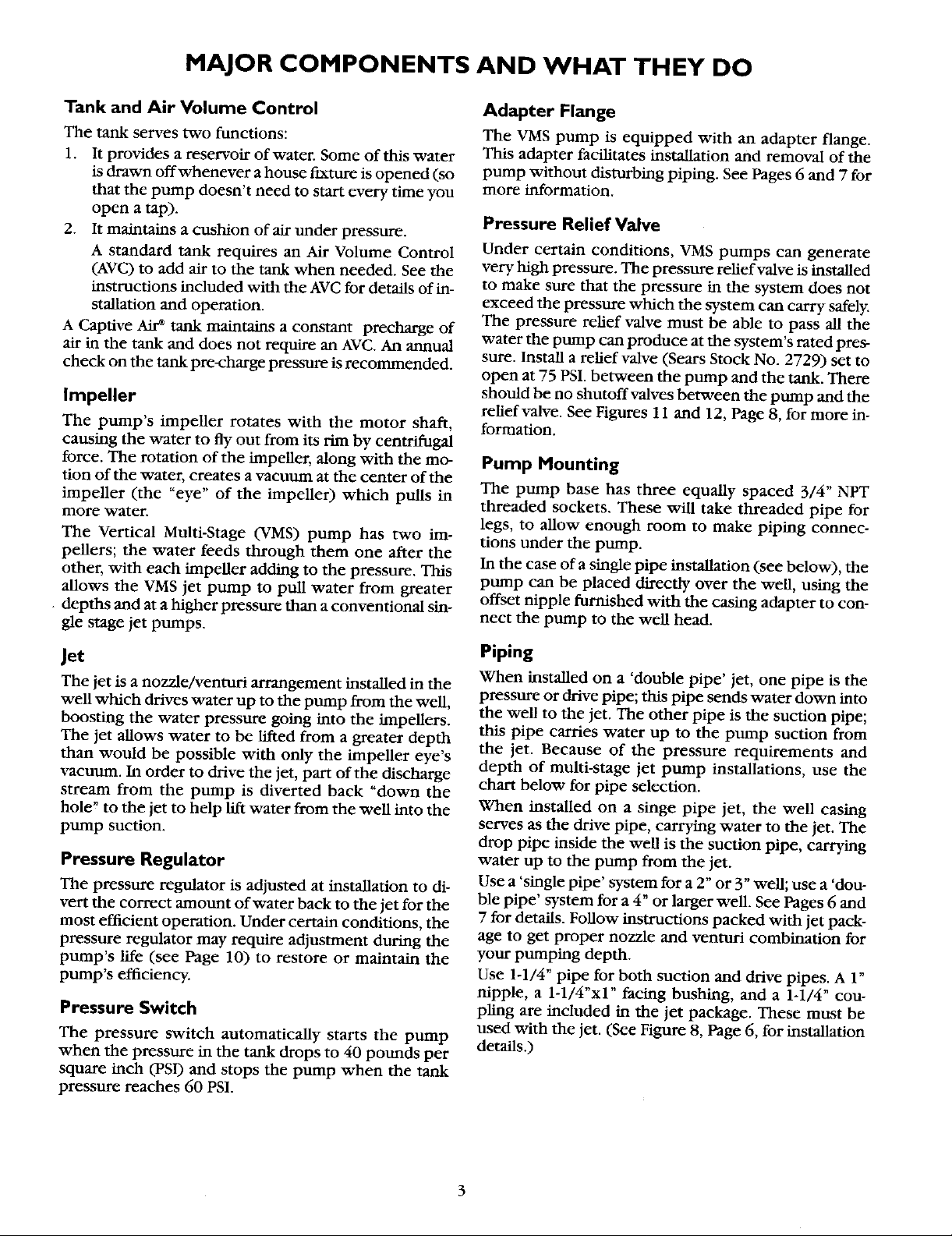
PUMP PERFORMANCE
Multi-Stage Pump
Pump Performance (in gallons per minute)
Pump Jet Discharge
Stock Pkg. Pressure Pumping Depth In Feet
No. No. P.S,I, 40 60 70 80 90 100 110 120 140 160 180 210
2967* 40 11.3 10,0 8.8 7,6 6,5 5,0 5,0 5,0 4.2 3,5 2.0
390.2532 29902**t 40 11.7 11.1 10.2 9.2 7.8 6,4 5.1 5.0 4.5 4.0 3.2 2.1
1 HP 60 11.0 9.5 8.6 7.8 6.6 5.4 4.7 4.6 4,2 3.4 2.6 1.7
29660*** 40 11.7 11.1 10.2 9.2 7.8 6.4 5,1 5.0 4.5 4,0 3.2 2.1
Use 160 PSI Min. Rating Plastic Pipe.
* Jet Package No. 2967- 2" Single Pipe (use 1-1/4" galvanized pipe).
** Jet Package No. 29902 - 3" Single Pipe (use 1-1/4" galvanized pipe).
*** Jet Package No. 29660 - 4" Double Pipe.
t Must be ordered through Sears Product Service, 1-800-366-7278.
60 10.6 8.6 7.5 6.5 5.5 4,8 4.8 4.7 3.9 2.7 1.5
60 11.O 9.5 8.6 7.8 6.6 5.4 4.7 4.6 4.2 3,4 2,6 1.7
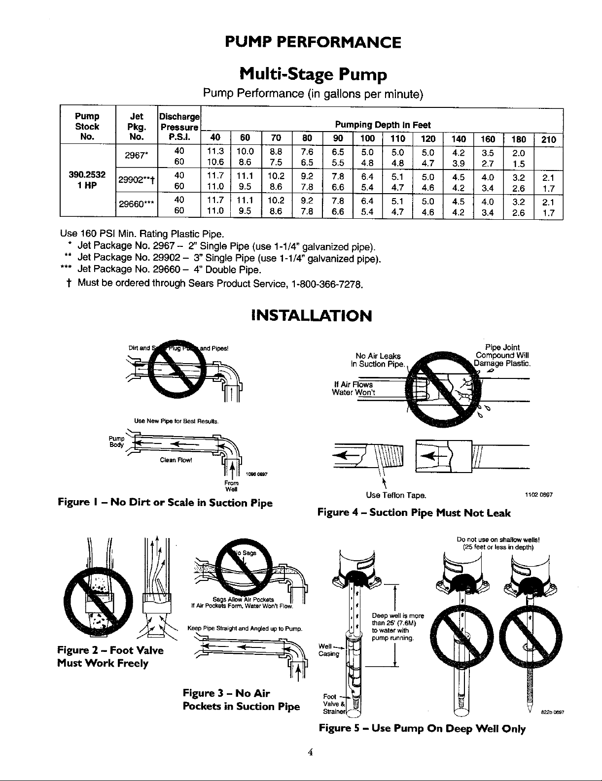
INSTALLATION
Use New Pipe for Best Results.
Clean FJow!
1096 0697
From
Well
Figure I - No Dirt or Scale in Suction Pipe
!
NoAir Leaks _ Compound Will
PipeJoint
in Suction Pipe. _amage Plastic.
IfAir Flows
Water Won't
Use TeflonTape.
Figure 4 - Suction Pipe Must Not Leak
1102 0697
Figure 2 - Foot Valve
Must Work Freely
Figure 3 - No Air
Pockets in Suction Pipe _,_
Figure 5 - Use Pump On Deep Well Only
INSTALLATION
NOTICE: For proper performance, pump MUST be
matched to ejector and to well depth. Use this pump
on wells 25' to 210' deep.
1. Long runs and many fittings increase friction and re-
duce flow. Locate pump as close to well as possible:
use as few elbows and fittings as possible.
2. Be sure well is clear of sand. Sand will plug the
pump and void the warranty.
3. Protect pump and all piping from freezing. Freezing
will split pipe, damage pump and void the warranty.
Check locally for frost protection requirements
(usually pipe must by 12 _ below frost line and
pump must be insulated).
4. Be sure all pipes and foot valve are clean and in
good shape.
5. No air pockets in suction pipe.
6. No leaks in suction pipe. Use Teflon tape or Plasto-
Joint stik to seal pipe joints.
7. Match pump to well.
IMPORTANT: Flow into well must at least equal
flow out through pump!
8. Unions installed near pump and well will aid in ser-
vicing. Leave room to use wrenches.
I_, CAUTION]Motor normally operates at high temper-
ature and will be too hot to touch. It is protected from
heat damage during operation by an automatic internal
cutoff switch. Before handling pump or motor, stop
motor and allow it to cool for 20 minutes.
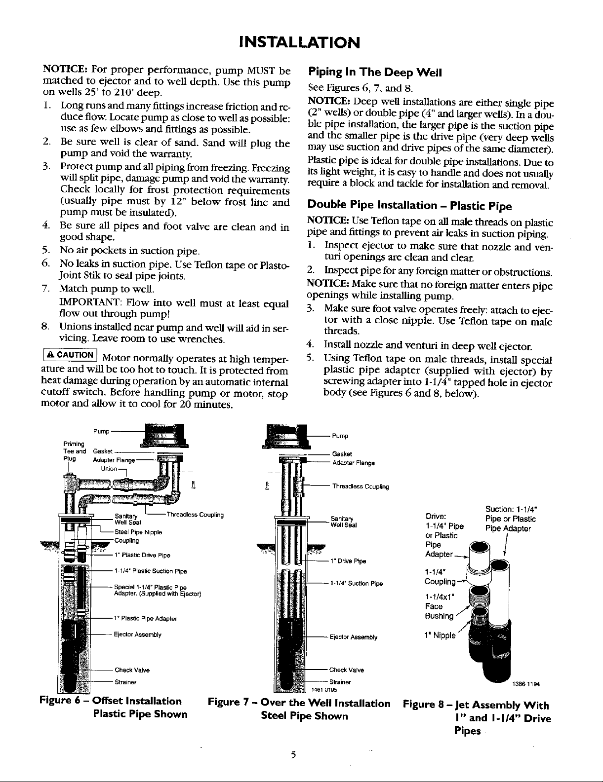
Piping In The Deep Well
See Figures 6, 7, and 8.
NOTICE: Deep well instaUations are either single pipe
(2" wells) or double pipe (4" and larger wells). In a dou-
ble pipe installation, the larger pipe is the suction pipe
and the smaller pipe is the drive pipe (very deep wells
may use suction and drive pipes of the same diameter).
Plastic pipe is ideal for double pipe instaUations. Due to
its light weight, it is easy to handle and does not usually
require a block and tackle for instaUation and removal.
Double Pipe Installation - Plastic Pipe
NOTICE: Use Teflon tape on all male threads on plastic
pipe and fittings to prevent air leaks in suction piping.
1. Inspect ejector to make sure that nozzle and ven-
turi openings are clean and clear.
2. Inspect pipe for any foreign matter or obstructions.
NOTICE: Make sure that no foreign matter enters pipe
openings while installing pump.
3. Make sure foot valve operates freely: attach to ejec-
tor with a close nipple. Use Teflon tape on male
threads.
.
Install nozzle and venturi in deep well ejector.
5.
Using Teflon tape on male threads, install special
plastic pipe adapter (supplied with ejector) by
screwing adapter into 1-1/4" tapped hole in ejector
body (see Figures 6 and 8 below).
Pnming
Tee and Gasket
Piug
)e Nipple
_Coppling
Adapter.(SuPplied with Ejector)
Ipe Adapter
heckValve
trainer
Figure 6 - Offset Installation
Plastic Pipe Shown
Gasket
Suction: 1-1/4"
Ddve: Pipe or Plastic
1-1/4" Pipe Pipe Adapter
Pipe
or Plastic J
1-1/4"
pe
1461 O_g5
Figure 7 - Over the Well Installation
Steel Pipe Shown
pe
1-1/4x1"
Face
1' Ni
1386 1194
Figure 8 - Jet Assembly With
I" and I-I/4" Drive
Pipes
5
INSTALLATION
6. Thread a 1" plastic pipe adapter or a 1" nipple into
the 1" tapped hole in ejector body (see lfigure 8).
7. Install sufficient plastic pipe in well casing to place
ejector at the proper depth. (Your well driller
should supply this information.)
NOTICE: As a guide, the ejector should be set at least
10 to 20 feet below the lowest water level with pump
running, if possible, but always at least five feet from
the bottom of the well.
8.
Tighten all hose clamps securely on plastic pipe.
Use two clamps per joint to prevent air leaks into
suction pipe. Clamp screws should be on opposite
sides of the pipe. Fill pipes with water to make sure
that foot valve and connections do not leak.
9. Install sanitary well seal on top of well casing; use
steel nipple through well seal as shown in Figure 6.
NOTICE: Align locating lugs on adapter flange and
pump base so that pump discharge will be aligned with
piping.
10. Install 1" nipple in one side of adapter flange. Slide
threadless coupling down over drive pipe from
well. Thread adapter flange onto suction pipe from
well and align nipple and drive pipe.
11. Slide threadless coupling up and secure nipple to
drive pipe.
12. Remove paper backing from adhesive gasket. Apply
gasket to adapter flange, making sure that holes line
up.
13. Align locating lugs on pump base with locating lugs
on adapter flange; attach pump to flange with cap
screws provided.
14. See "Discharge Pipe Sizes" for information regard-
hag correct discharge pipe size.
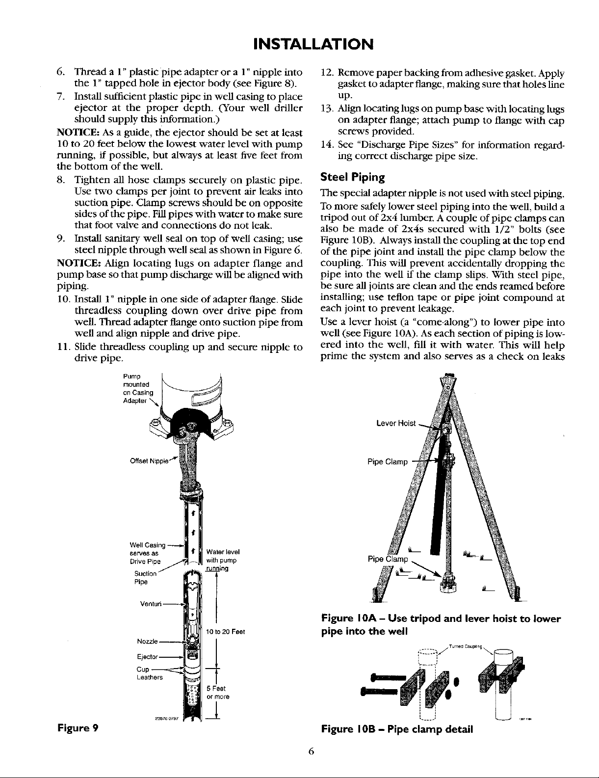
Steel Piping
The special adapter nipple is not used with steel piping.
To more safely lower steel piping into the well, build a
tripod out of 2x4 lumber. A couple of pipe clamps can
also be made of 2x4s secured with 1/2" bolts (see
Figure 10B). Always install the coupling at the top end
of the pipe joint and install the pipe clamp below the
coupling. This will prevent accidentally dropping the
pipe into the well if the clamp slips. With steel pipe,
be sure all joints are clean and the ends reamed before
installing; use teflon tape or pipe joint compound at
each joint to prevent leakage.
Use a lever hoist (a "come-along") to lower pipe into
well (see Figure 10A). As each section of piping is low-
ered into the well, fill it with water. This will help
prime the system and also serves as a check on leaks
Pump
mounted
on Casing
serves as
Drive Pipe
Pipe
Waterlevel
with pump
riiing
1Oto20 Feet
Lever Hoist
Pipe Clamp -
Pipe Clamp _ _ll_-L
Figure I0A - Use tripod and lever hoist to lower
pipe into the well
Figure 9
Leathers
5 Feet
or mere
i ,
Figure I0B - Pipe clamp detail
 Loading...