

Craftsman 3902522, 390252281, 3902519 Owner’s Manual
SEARS
OWNER'S
MANUAL
MODELNO.
390.2519
390.2522
@
CAUTION:
Read and Fallow
All Safety Rulesand
Operating Instructions
BeforeFirstUseof
ThisProduct.
Save ThisManual For
FutureReference.
Sears, Roebuck and Co., Hoffman Estates, IL 60179 U.S.A.
I:RRFTSMRN°
PROFESSIONAL
"HYDROGLASS ''®
CONVERTIBLE DEEP
WELL JET PUMP
• Safety Instructions
• Installation
• Operation
• Troubleshooting
• Repair Parts
Form No. F642-04076 (Rev. 3/11/05)
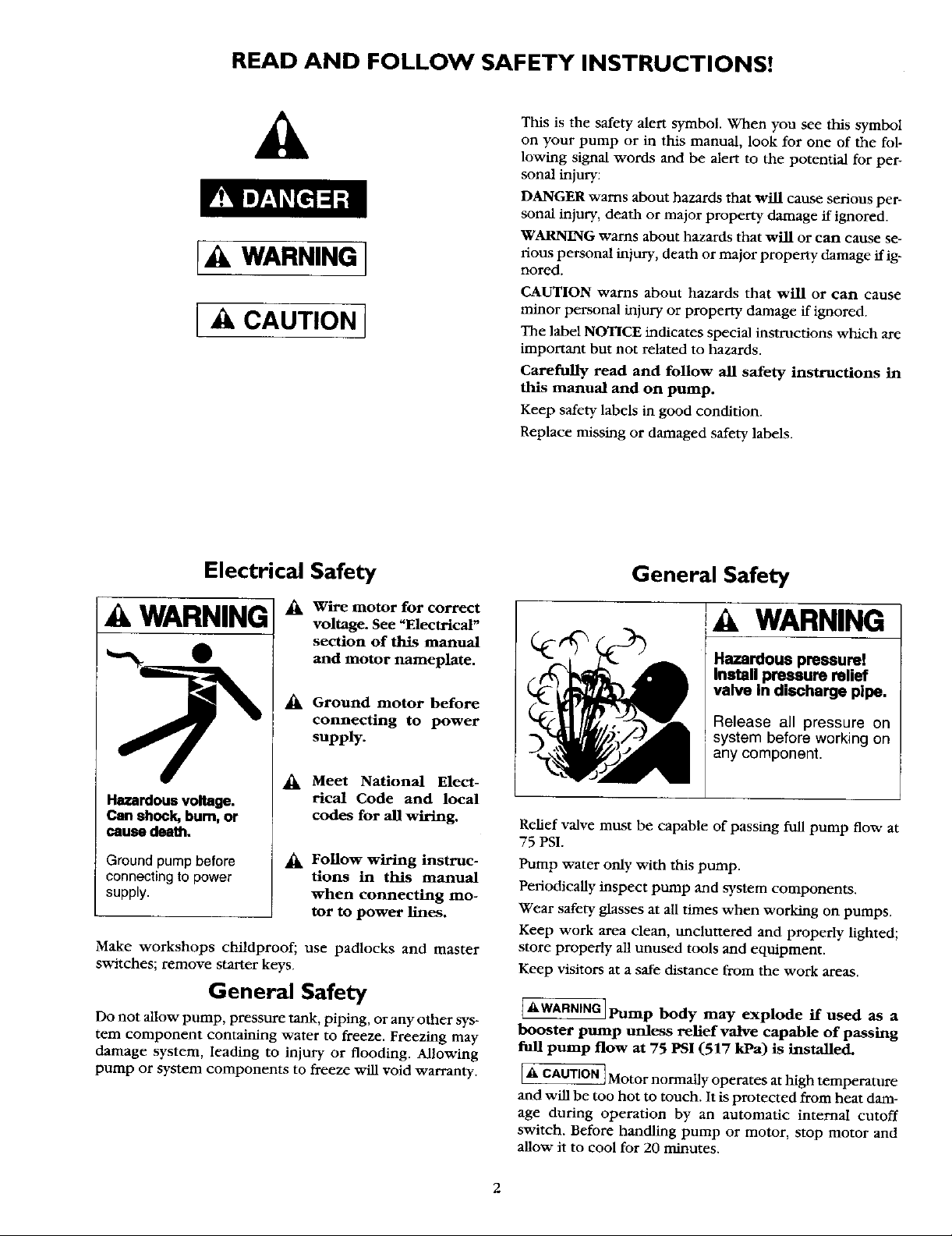
READ AND FOLLOW SAFETY INSTRUCTIONS!
This is the safety alert symbol. When you see this symbol
A
WARNING 1
A CAUTION 1
on your pump or in this manual, look for one of the fol-
lowing signal words and be alert to the potential for per-
sonal injury:
DANGER warns about hazards that will cause serious per-
sonal injury, death or major property damage if ignored.
WARNING warns about hazards that will or can cause se-
rious personal injury, death or major property damage if ig-
nored.
CAUTION warns about hazards that will or can cause
minor personal injury or property damage if ignored.
The label NOTICE indicates special instructions which are
important but not related to hazards.
Carefully read and follow all safety instructions in
this manual and on pump.
Keep safety labels in good condition.
Replace missing or damaged safety labels.
Electrical Safety
A WARNING
Hazardous voltage.
Can shock, bum, or
cause death.
Ground pump before
connecting to power
supply.
Make workshops childproof; use padlocks and master
switches; remove starter keys.
_k Wire motor for correct
voltage. See "Electrical"
section of this manual
and motor nameplate.
_k Ground motor before
connecting to power
supply.
Meet National Elect-
rical Code and local
codes for all wiring.
Follow wiring instruc-
tions in this manual
when connecting mo-
tor to power lines.
General Safety
Do not allow pump, pressure tank, piping, or any other sys-
tem component containing water to freeze. Freezing may
damage system, leading to injury or flooding. Allowing
pump or system components to freeze v_dl void warranty.
General Safety
WARNING
Hazardous pressure!
Install pressure relief
valve In discharge pipe.
Release all pressure on
system before working on
any component.
Relief valve must be capable of passing full pump flow at
75 PSI.
Pump water only with this pump.
Periodically inspect pump and system components.
Wear safety glasses at all times when working on pumps.
Keep work area clean, tmclunered and properly lighted;
store properly all unused tools and equipment.
Keep visitors at a safe distance from the work areas.
AWARNINGIPump body may explode if used as a
booster pump unless relief valve capable of passing
full pump flow at 75 PSI (517 kPa) is installed.
[_ CAUTION]Motor normally operates at high temperature
and will be too hot to touch. ]t is protected from heat dam-
age during operation by an automatic internal cutoff
switch. Before handling pump or motor, stop motor and
allow it to cool for 20 minutes.
I
2
CONTENTS
Safety .................................................................................. 2
Warranty/Introduction ....................................................... 3
Installation ....................................................................... 4-8
Electrical ........................................................................ 9-10
Operation ......................................................................... 11
Maintenance ..................................................................... 11
Service ......................................................................... 12-13
Troubleshooting .......................................................... 14-15
Pump Performance .......................................................... 15
Repair Parts ................................................................. 16-19
of charge.
During the Second year and third year from purchase date, a free pump part will be supplied for a defective one.
You must pay the labor cost if you wish to have it installed.
Warranty service is available by returning this product to place of purchase for replacement, or by calling
1-800-4-MY-HOME ®to arrange for part replacement or product repair.
This warranty is VOID if this pump is used for commercial or rental purposes.
Sears is not liable for loss or damage to property, nor for any incidental or consequential loss or expense from
property damage, that results directly or indirectly from the use of this product.
This warranty gives you specific legal rights, and you may also have other fights which vary from state to state.
Sears Roebuck and Co., Dept. 817WA, Hoffman Estates, IL 60179
INTRODUCTION
We suggest you take a few minutes to read the instructions
contained in this manual before installing and using your
pump. This viifi help you obtain the full benefits of the qual-
ity and convenience built into this equipment. It will also
help you avoid any needless service expense resulting from
causes beyond our control which naturally cannot be cov-
eredinourwarranty.
RULES FOR SAFE INSTALLATION AND OPERATION
1. Read the Owners Manual and Rules for Safe Operation
and Installation Instructions careflifiy. Failure to follow
these Rules and Instructions could cause serious bodily
injury, and/or property damage.
2. Check your local electrical wiring codes before installa-
tion. ffyour local codes are not followed, your pump will
not work to its full rated capacity. If in doubt, contact
your local Power Company.
3. Be certain your pump installation meets all local plumb-
hag, pump and well codes.
4. While installing the pump, always keep the well covered
to prevent leaves and foreign matter from falling into the
well and contaminating the water and/or causing possi-
ble serious damage to the mechanical operation of the
pump.
5. Always test the well water for purity before using. Check
with local health department for testing procedure.
6. Before installing or servicing your pump, BE CERTAIN
pump power source is disconnected.
7. Be sure your pump electrical circuit is properly gruunded.
8. Complete pump and piping system MUST be protected
against below freezing temperature. Failure to do so could
cause severe damage and voids the Warranty.
9. Make sure the line voltage and frequency of the electrical
circuit supply agree with the motor wiring. If motor is
dual voltage type, BE SURE it is wired correctly for your
power supply.
10. The correct fusing and wiring sizing is essential to proper
motor operation. Recommended flWmg and v/ire size data
is in the manual.
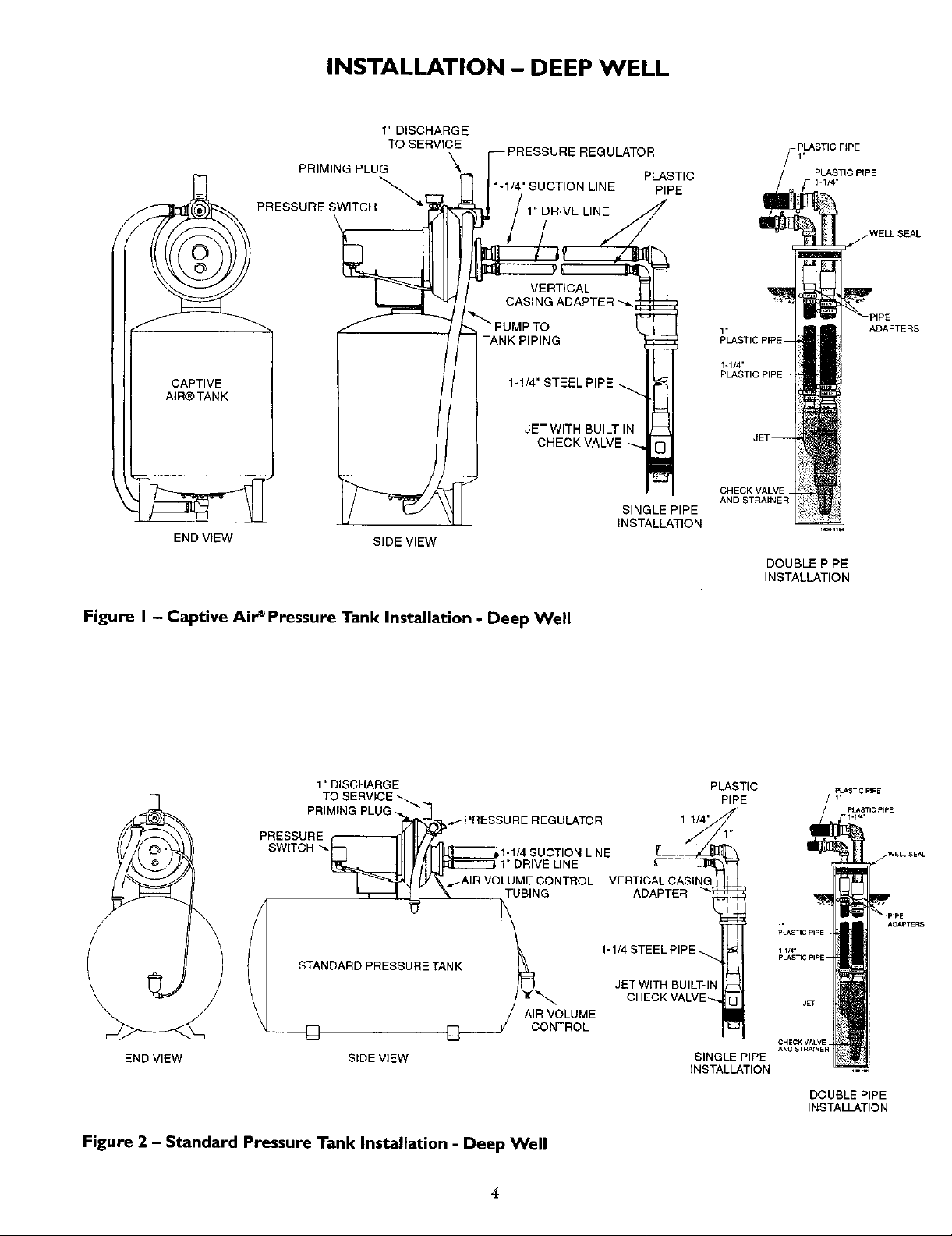
INSTALLATION - DEEP WELL
1" DISCHARGE
TO SERVICE
PRIMING PLUG
PRESSURE SWITCH !
_ 1-1/4" SUCTION LINE PIPE
\
\
IE REGULATOR
LINE
PLASTIC
1,
PLASTIC PIPE
WELLSEAL
CAPTIVE
AIR_ TANK
END VIEW
SIDE VIEW
1-1/4"
CHECK\
Figure I - Captive Air'Pressure Tank Installation - Deep Well
SINGLE PIPE
INSTALLATION
1.
PLASTIC PIPE--
1-1/4"
PLASTIC PIP
CHECKVALVE_
AND STRAINER
DOUBLE PIPE
INSTALLATION
ADAPTERS
1" DISCHARGE
TO SERVICE _.
PRIMING PLUG
_IMING PLUG
PRESSURE
SWITCH
-_ "_H_ _- PRESSURE REGULATOR 1-1/4"
1-1/4 SUCTION LINE
_._--IJl !II_:_E==_1"DRIVE LINE
.,_-AIR VOLUME CONTROL VERTICALCASING
_AIR VC TUBING ADAPTER
STANDARD PRESSURE TANK
_AIG 1-1/4 STEEL PIP
AIR VOLUME
D
END VIEW SIDE VIEW
Figure 2 - Standard Pressure Tank Installation - Deep Well
PLASTIC
PIPE
JET WITH BUILT-In
CHECK VALVE
ONTROL
SINGLE PIPE
INSTALLATION
DOUBLE PIPE
INSTALLATION
INSTALLATION - SHALLOW WELL
1" DISCHARGE
TO SERVICE
PRIMING PLUG
PRESSURE SWITCH
CHECK VALVE
ULATOR
L JET
'-"4"p,pE',
VALVE)
PING
1-1/4' STEEL
DRIVE PiPE
DRIVE
CAPTIVE
AIR®TANK
END VIEW
COUPLING
WELL POINT _._
SIDE VIEW DRIVEN POINT
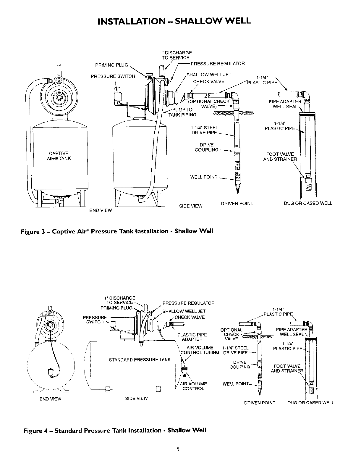
Figure 3 - Captive Air _ Pressure Tank Installation - Shallow Well
PIPE ADAPTER
I
PLASTIC PIPE. •
FOOT VALVE
AND STRAIN
'-"4"l
DUG OR CASED WELL
1" DISCHARGE
TO SERVICE _.. PRESSURE REGULATOR
PRIMING
PRESSURE _SNA:OHWE_K VALVE
SWITCH "__
'I
i CONTROLTUBING DRIVE PIPE_
END VIEW SIDE VIEW
PLUG
_[_f/SHALLOW WELL JET
,-, PLASTIC PIPE
STANDARD PRESSURE TANK _;; DRIVE __
ADAPTER
AIR VOLUME
i_ COUPING
/ AiR VOLUME
CONTROL
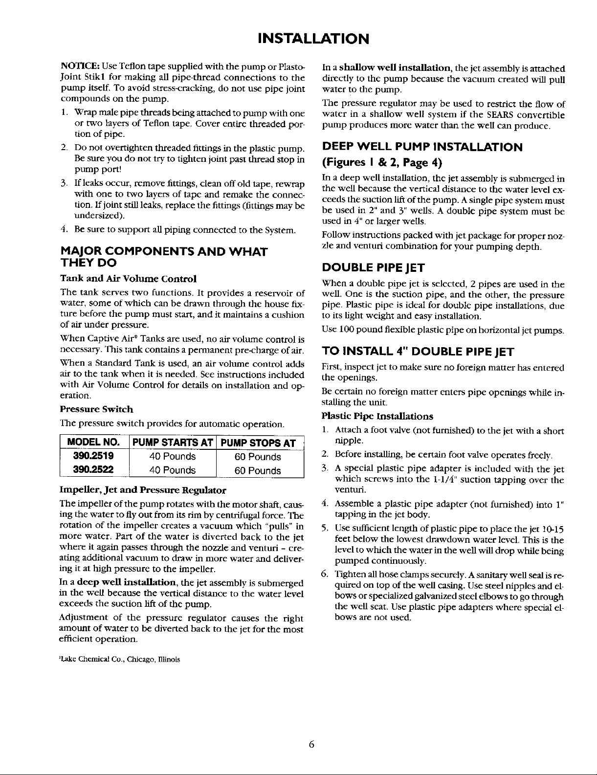
Figure 4 - Standard Pressure Tank Installation - Shallow Well
5
I-1/4"
j. PLASTIC PIPE,
OPTIONAL 4p PIPE ADAPTER
CHECK
VALVE
1-1!4" STEEL i
WELL POINT--_
DRIVEN POINT DUG OR CASED WELL
1-1/4'
PLASTIC PIPE.
FOOT VALVE
AND STRAINER
INSTALLATION
NOTICE: Use Teflon tape supplied with the pump or Plasto-
Joint Stikl for making all pipe-thread connections to the
pump itself. To avoid stress-cracking, do not use pipe joint
compounds on the pump.
1. Wrap male pipe threads being attached to pump with one
or two layers of Teflon tape. Cover entire threaded por-
tion of pipe.
2. Do not overtighten threaded fittings in the plastic pump.
Be sure you do not try to tighten joint past thread stop in
pump port!
3. If leaks occur, remove fittings, clean off old tape, rewrap
with one to two layers of tape and remake the connec-
tion. If joint still leaks, replace the fittings (fittings may be
undersized).
4. Be sure to support all piping connected to the System.
MAJOR COMPONENTS AND WHAT
THEY DO
Tank and Air Volume Control
The tank serves two functions. It provides a reservoir of
water, some of which can be drawn through the house fix-
ture before the pump must start, and it maintains a cushion
of air under pressure.
When Captive Air + Tanks are used, no air volume control is
necessary. This tank contains a permanent pre-charge of air.
When a Standard Tank is used, an air volume control adds
air to the tank when it is needed. See instructions included
with Air Volume Control for details on installation and op-
eration.
Pressure Switch
The pressure switch provides for automatic operation.
MODEL NO. PUMP STARTS AT PUMP STOPS AT
390.2519 40 Pounds 60 Pounds
390.2522 40 Pounds 60 Pounds
Impeller, Jet and Pressure Regulator
The impeller of the pump rotates with the motor shaft, caus-
ing the water to fly out from its rim by centrifugal force. The
rotation of the impeller creates a vacuum which "puns" in
more water. Part of the water is diverted back to the jet
where it again passes through the nozzle and venturi - cre-
ating additional vacuum to draw in more water and deliver-
ing it at high pressure to the impeller.
In a deep well installation, the jet assembly is submerged
in the well because the vertical distance to the water level
exceeds the suction lift of the pump.
Adjustment of the pressure regulator causes the fight
amount of water to be diverted back to the jet for the most
efficient operation.
In a shallow well installation, the jet assembly is attached
directly to the pump because the vacuum created will pull
water to the pump.
The pressure regulator may be used to restrict the flow of
water in a shallow well system if the SEARS convertible
pump produces more water than the well can produce.
DEEP WELL PUMP INSTALLATION
(Figures I & 2, Page 4)
In a deep well installation, the jet assembly is submerged in
the well because the vertical distance to the water level ex-
ceeds the suction lift of the pump. A single pipe system must
be used in 2" and 3" wells. A double pipe system must be
used in 4" or larger wells.
Follow instructions packed with jet package for proper noz-
zle and venturi combination for your ptmaping depth.
DOUBLE PIPE JET
When a double pipe jet is selected, 2 pipes are used in the
well. One is the suction pipe, and the other, the pressure
pipe. Plastic pipe is ideal for double pipe installations, due
to its light weight mid easy installation.
Use 100 ponnd flexible plastic pipe on horizontal jet pumps.
TO INSTALL 4" DOUBLE PIPE JET
First, inspect jet to make sure no foreign matter has entered
the openings.
Be certain no foreign matter enters pipe openings while in-
stalling the unit.
Plastic Pipe Installations
1. Attach a foot valve (not furnished) to the jet with a short
nipple.
2. Before installing, be certain foot valve operates freely.
3. A special plastic pipe adapter is included with the jet
which screws into the 1-1/4" suction tapping over the
venturi.
4. Assemble a plastic pipe adapter (not furnished) into 1"
tapping in the jet body.
5. Use sufficient length of plastic pipe to place the jet 10-15
feet below the lowest drawdown water level. This is the
level to which the water in the well will drop while being
pumped continuously.
6. Tighten all hose clamps securely. A sanitary well seal is re-
quired on top of the well casing. Use steel nipples and el-
bows or specialized galvanized steel elbows to go through
the well seat. Use plastic pipe adapters where special el-
bows are not used.
_Lake Chemical Co., Chicago, Blinois
6
 Loading...