

Craftsman 3902518, 390251480, 390251401 Owner’s Manual
SEARS
OWNER'S
MANUAL
MODEL NO.
390.2514
390.2518
CAUTION:
Read and Follow
All Safety Rulesand
Operating Instructions
Before FirstUseof
ThisProduct.
Save ThisManual For
FutureReference.
Sears, Roebuck and Co., Hoffman Estates, IL 60179 U.S.A.
PRINTED IN USA
I:RRFTSMRN°
PROFESSIONAL
"HYDROGLASS ''®
SHALLOW WELL JET PUMP
• Safety Instructions
• Installation
• Operation
• Troubleshooting
• Repair Parts
Form No. F642-04073 (8/3/o4)
READ AND FOLLOW SAFETY INSTRUCTIONS!
This is the safety aler'c symbol. When you see this symbol on your
pump or in this manual, look for one of the following signal words
and be alert to the potential for personal injury:
DANGER warns about hazards that will cause serious personal
injury, death or major property damage ff ignored.
WARNING warns about hazards that will or can cause serious
personal injury, death or major property damage ff ignored.
CAUTION warns about hazards that will or can cause minor per-
sonal injury or property damage ff ignored.
The label NOTICE indicates special instructions which are im-
portant but not related to hazards.
Carefully read and follow all safety instructions in this
manual and on pump.
Keep safety labels in good condition.
Replace missing or damaged safety labels.
Relief valve must be capable of passing full pump flow at 75 PSI.
Pump water onJy with this pump.
Electrical Safety
WARNING
Hazardous voltage.
Can shock, burn, or
cause death.
Ground pump before
connecting to power
supply.
Make workshops childproof; use padlocks and master switches;
remove starter keys.
General Safety
Do not allow pump, pressure tank, piping, or any other system
component containing water to freeze. Freezing may damage sys-
tem, leading to injury or flooding. Allowing pump or system com-
ponents to freeze will void warranty.
_k Wire motor for correct
voltage. See "Electrical"
section of this manual
and motor nameplate.
Ground motor before
connecting to power
supply.
Meet National Elect-
rical Code and local
codes for all wiring.
_k Follow wiring instruc-
tions in this manual
when connecting mo-
tot to power lines.
General Safety
WARNING
Hazardous pressure!
Install pressure relief
valve in discharge pipe.
Release all pressure on
system before working on
any component.
Periodically inspect pump and system components.
Wear safety glasses at all times when worldng on pumps.
Keep work area clean, uncluttered and properly lighted; store
properly all unused tools and equipment.
Keep visitors at a safe distance from the work areas.
A WARNIN__j Pump body may explode if used as a booster
pump unless relief valve capable of passing full pump flow
at 75 PSI (517 kPa) is installed,
f
Iax CAUTION !Motor normally operates at high temperature and
will be too hot to touch. It is protected from heat damage during
operation by an automatic internal cutoff switch. Before handling
pump or motor, stop motor and allow it to cool for 20 minutes.
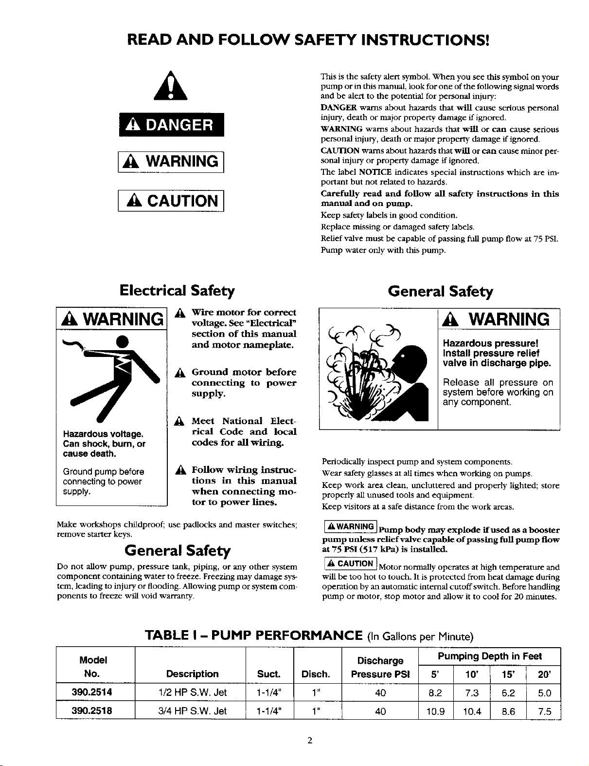
TABLE I - PUMP PERFORMANCE (In Gallonsper Minute)
Model Discharge Pumping Depth in Feet
No. Description Suct. Disch. Pressure PSI 5' 10' 15' 20'
390.2514 1/2 HP S.W. Jet 1-1/4" 1" 40 8.2 7.3 6.2 5.0
390.2518 3/4 HP S.W. Jet 1-1/4" 1" 40 10.9 10.4 8.6 7.5
2
CONTENTS
Safety .............................................................................................. 2
Warranty/Introduction ................................................................... 3
Pump Performance ........................................................................ 3
Major Components ...................................................................... 3"_
Piping ............................................................................................. 4
Electrical ...................................................................................... 5_
Installation ...................................................................................... 7
Operation ....................................................................................... 7
Maintenance ................................................................................ 8-9
Helpful Hints .................................................................................. 9
Repair Parts ............................................................................. 10-11
Troubleshooting Guide ................................................................ 12
INTRODUCTION
We suggest you take a few minutes to read the instructions con-
tained in this manual before installing and using your pump. This
will help you obtain the full benefits of the quality and convenience
built into this equipment. It will also help you avoid any needless
service expense resulting from causes beyond our control which
naturally cannot be covered in our warranty.
Dell
RULES FOR SAFE INSTALLATION AND OPERATION
1. Read the Owners Manual and Rules for Safe Operation and
Installation Instructions carefially. Failure to follow these Rules
and Instructions cotfld cause serious bodily injury, and!or prop-
erry damage.
2. Check your local electrical wiring codes before installation, ff
your local codes are not followed, your pump will not work to
its full rated capacity. If in doubt, contact your local Power
Company.
3. Be certain your pump installation meets all local plumbing,
pump and well codes.
4. While installing the pump, always keep the well covered to pre_
vent leaves and foreign matter from falling into the well and con-
taminating the water and/or causing possible serious damage to
the mechanical operation of the pump.
5. Always test the well water for purity before using. Check with
local health department for testing procedure.
6. Before installing or servicing your pump, BE CERTAIN pump
power source is disconnected.
7. Be sure your pump electrical circuit is properly grounded.
8. Complete pump and piping system MUST be protected against
below freezing temperature. Failure to do so could cause severe
damage and voids the Warrant3,.
9. Make sure the line voltage and frequency of the electrical circnit
supply agree with the motor wiring. If motor is dual voltage
type, BE SURE it is wired correctly for your power supply.
10. The correct fusing and wiring sizing is essential to proper motor
operation. Recommended fusing and wire size data is in the
manual.
MAJOR COMPONENTS / PIPING
MAJOR COMPONENTS
AND WHAT THEY DO
NOTICE: Use Teflon tape supplied with the pump for making all
threaded connections to the pump.
Impeller and Jet
Impeller turns with motor shaft, causing water to fly out from its
rim by centrifugal force. Impeller rotation creates a vacuum which
pulls in more water. Part of the water is diverted back to the jet
where it passes through the nozzle and venturi. This creates more
vacuum to draw in more water.
In shallow wells (less than 20 feet deep), the vacuum created at the
pump is enough to pull water to the pump. Therefore, the jet as-
sembly is built into the pump.
Air Volume Control
The air volume control (AVC) maintains the cushion of air in
Standard tanks.
Pressure Switch
The pressure switch provides automatic control.
MODEL NO. PUMP STARTS AT PUMP STOPS AT
390.2514 40 PSI 60 PSI
390.2518 40 PSI 60 PSI
Tank
The tank serves two functions. It provides a reservoir of water,
some of which can be drawn through the house fixture before the
pump must start. It maintains a cushion of air under pressure.
Two types of tanks are available. Captive _ and Standard. No air
volume control is needed with Captive Air* Tanks.
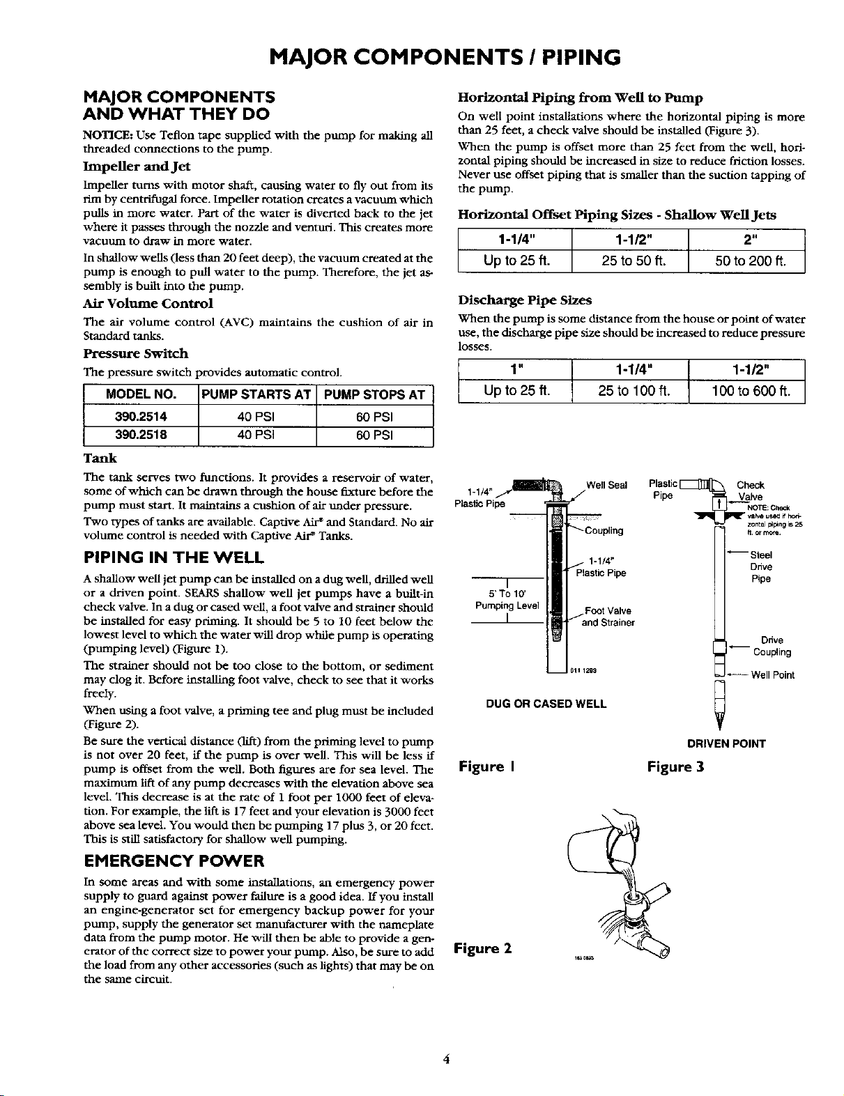
PIPING IN THE WELL
A shallow well jet pump can be installed on a dug well, drilled well
or a driven point. SEARS shallow well jet pumps have a built-in
check valve. In a dug or cased well, a foot valve and strainer should
be installed for easy priming. It should be 5 to 10 feet below the
lowest level to which the water will drop while pump is operating
(pumping level) (Figure 1).
The strainer should not be too close to the bottom, or sediment
may clog it. Before installing foot valve, check to see that it works
freely.
When using a foot valve, a priming tee and plug must he included
(Figure 2).
Be sure the vertical distance (lift) from the priming level to pump
is not over 20 feet, if the pump is over well This will be less if
pump is offset from the well. Both figures are for sea level. The
maximum lift of any pump decreases with the elevation above sea
level. This decrease is at the rate of 1 foot per 1000 feet of eleva-
tion. For example, the lift is 17 feet and your elevation is 3000 feet
above sea level. You would then be pumI:Cmg 17 plus 3, or 20 feet.
This is still satisfactory for shallow well pumping.
EMERGENCY POWER
In some areas and with some installations, an emergency power
supply to guard against power failure is a good idea. If you install
an engine-generator set for emergency backup power for your
pump, supply the generator set manufacturer with the nameplate
data from the pump motor. He will then be able to provide a gen-
erator of the correct size to power your pump. Klso, be sure to add
the load from any other accessories (such as lights) that may be on
the same circuit.
Horizontal Piping from Well to Pump
On well point installations where the horizontal piping is more
than 25 feet, a check valve should be installed (Figure 3).
When the pump is offset more than 25 feet from the well, hori-
zontal piping should be increased in size to reduce friction losses.
Never use offset piping that is smaller than the suction tapping of
the pump.
Horizontal Offset Piping Sizes - Shallow Well Jets
1-114" 1-1/2" 2"
Up to 25 ft. 25 to 50 ft. 50 to 200 ft.
Discharge Pipe Sizes
When the pump is some distance from the house or point of water
use, the discharge pipe size should be increased to reduce pressure
losses.
1" 1-1/4" 1-112"
Upto 25 ft. 25 to 100 ft. 100 to 600 ft.
1-1/4"
PlasticPipe
F
5'To 10'
PumpingLevel FootValve
WellSeal
PlasticPipe
Pipe ._VaVak,e
PlasticC_CvheC k
NOTE: Chec_
vabe u_e_ i_ hc_
zomel _pmg =s25
Steel
Drive
Pipe
L andStrainer
h. or more.
Ddve
-- Coupling
_=J_ Well Point
DUG OR CASED WELL
DRIVEN POINT
Figure I
Figure 3
Figure 2
ELECTRICAL
Disconnect power before working on pump, motor, pressure switch, or wiring.
Motor Switch Settings
If the motor can operate at either 115 or 230 volts, it is set at the
factory to 230 volts. Do not change motor voltage setting if line
voltage is 230 volts, or if you have a single voltage motor.
NOTICE: Never wire a 115 volt motor to a 230 volt line.
Remove Motor End Cover
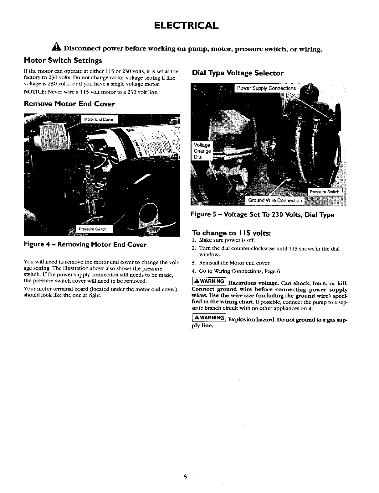
Dial Type Voltage Selector
Power Supply Connections
PressureSwitch
Ground Wire Connection
Figure 4 - Removing Motor End Cover
You will need to remove the motor end cover to change the volt-
age setting. The illustration above also shows the pressure
switch. If the power supply connection still needs to be made,
the pressure switch cover will need to be removed.
Your motor terminal board (located under the motor end cover)
should look like the one at right.
Figure 5 - Voltage Set To 230 Volts, Dial Type
To change to I 15 volts:
1. Make sure power is off.
2. Tuna the dial counter-clockwise until 115 shows in the diai
window.
3. Reinstall the Motor end cover
4. Go to Wiring Connections, Page 6.
IAWARNING JHazardous voltage. Can shock, burn, or kilL
Connect ground wire before connecting power supply
wires. Use the wire size (including the ground wire) speci-
fied in the wiring chart. If possible, connect the pump to a sep-
arate branch circuit with no other appliances on it.
_ Explosion hazard. Do not ground to a gas sup
ply line.
 Loading...