

Craftsman 3902508 Owner’s Manual
I
SEARS
OWNER'S
MANUAL
MODEL NO.
390.2508
CAUTION:
Read andFollow
All Safety Rulesand
Operating Instructions
Before FirstUse of
ThisProduct.
CRAFTSMAN°
HYDROGLASS ®
SHALLOW WELL
JET PUMP
• Safety Instructions
• Installation
Save ThisManual For
FutureReference.
Sears, Roebuck and Co., Hoffman Estates, IL60179 U.S.A.
PRINTED IN USA. Form No F642-04072 (Rev 2/15/05)
• Operation
• Troubleshooting
• Repair Parts
CONTENTS
WaL'ranty .............................................................................. 2
Pump Performance .............................................................. 3
Major Components .............................................................. 3
Piping ................................................................................ 3-4
Installation ........................................................................... 4
Electrical .............................................................................. 5
Operation/Maintenance ................................................... 6-9
Helpful Hints ....................................................................... 9
Troubleshooting Guide ..................................................... 10
Repair Parts ........................................................................ 11
INTRODUCTION
Please read our instructions before installing and using your
pump. This will help you obtain the full benefits of the qual-
ity and convenience binh into this equipment. It will also
help you avoid any needless service expense resulting from
causes beyond our control which are not covered by our
waiTanty.
RULES FOR SAFE INSTALLATION AND OPERATION
1. Read the Owners Manual and Rules for Installation and
Safe Operation carefully. Failure to follow these Rules and
Instructions could cause serious bodily injury, and/or
property damage.
2. Check your local electrical wiring codes before installa-
tion. ffyour local codes are not followed, your pump will
not work to its full rated capacity and could present a fire
hazard, ff in doubt, contact your local power company.
3. BE SURE your pump installation meets all local plumb-
ing, pump and well codes.
4. While installing your pump, always keep the well covered
to prevent leaves and foreign matter from falling into the
well, contaminating the water and/or causing possible se-
rious damage to the mechanical operation of the pump.
5. Always test the water from well for purity before using.
Check with local health department for testing procedure.
6. Before installing or servicing your pump, BE SURE pump
power source is disconnected.
7. BE SURE your pump electrical circuit is properly
grounded.
8. Complete pump and piping system MUST be protected
against below freezing temperature. Allov_mg the pump
or piping to freeze could cause severe damage and voids
the Warranty.
9. BE SURE the llne voltage and frequency of the electrical
current supply agree with the motor wiring as shown on
motor nameplate.
10. The correct fusing and vdring sizing is essential to proper
motor operation. Recommended fusing and wire size data
is in the manual (Page 5).
11. Pump water only with this pump.
12. Periodically inspect pump and system components.
IA CAUTION 1Motor normally operates at high temperature
and wilt be too hot to touch. It is protected
from heat damage during operation by an automatic inter-
nal cutoff switch. Before handling pump or motor, stop
motor and allow it to cool for 20 minutes.
GENERAL INFORMATION
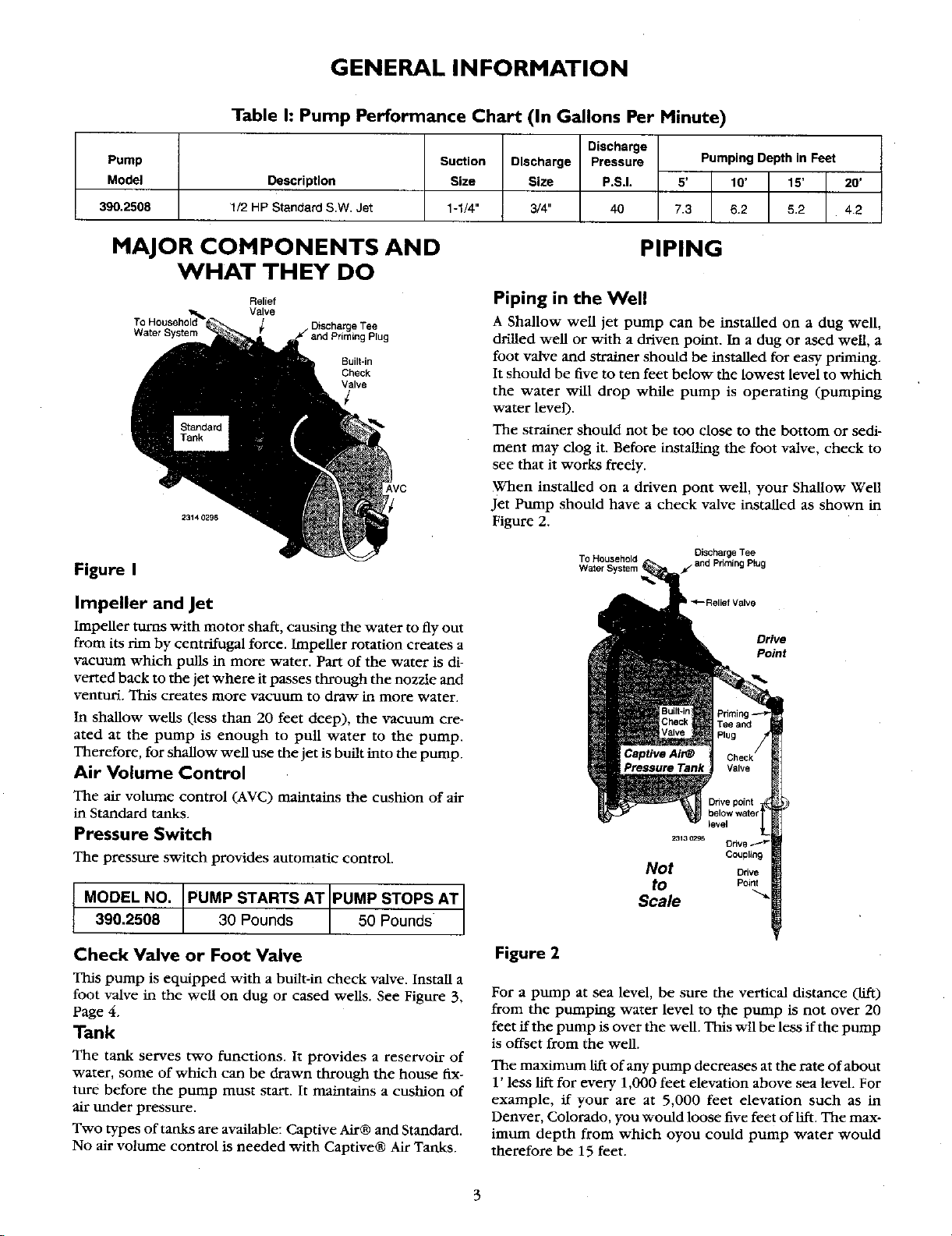
Table h Pump Performance Chart (In Gallons Per Minute)
Pump Suction Discharge Pressure Pumping Depthin Feet
Model Description Size Size P.S.I. 5' 10' 15' 20'
390.2508 1/2 HP Standard S.W. Jet 1-1/4" 3/4" 40 7.3 6.2 5.2 4.2
MAJOR COMPONENTS AND
Discharge
PIPING
WHAT THEY DO
Relief
Valve
Water System and Priming Plug
23140E96
ieTee
Built-in
Check
Valve
Figure I
Impeller and Jet
Impeller turns with motor shaft, causing the water to fly out
from its rim by centrifugal force. Impeller rotation creates a
vacuum which puUs in more water. Part of the water is di-
verted back to the jet where it passes through the nozzle and
venturi. This creates more vacuum to draw in more water.
In shallow wells (less than 20 feet deep), the vacuum cre-
ated at the pump is enough to pull water to the pump.
Therefore, for shallow well use the jet is built into the pump.
Air Volume Control
The air volume control (AVC) maintains the cushion of air
in Standard tanks.
Pressure Switch
The pressure switch provides automatic control.
MODEL NO. PUMP STARTS AT [PUMP STOPS AT
390.2508 _ / _
Piping in the Well
A Shallow well jet pump can be installed on a dug well,
drilled well or with a driven point. In a dug or ased well, a
foot valve and strainer should be installed for easy priming.
It should be five to ten feet below the lowest level to which
the water will drop while pump is operating (pumping
water level).
The strainer should not be too close to the bottom or sedi-
ment may clog it. Before installing the foot valve, check to
see that it works freely.
When installed on a driven pont well, your Shallow Well
Jet Pump should have a check valve installed as shown in
Figure 2.
To Household Discharge Tee
Water System f- and Priming Plug
II _--Relief Valve
Drive
Point
Couplin9
Not Orive
to Point
Scale
Check Valve or Foot Valve
This pump is equipped with a built-in check valve. Install a
foot valve in the well on dug or cased wells. See Figure 3,
Page 4.
Tank
The tank serves two functions. It provides a reservoir of
water, some of which can be drawn through the house fix-
ture before the pump must start. It maintains a cushion of
air under pressure.
Two types of tanks are available: Captive Air® and Standard.
No air vohtme control is needed with Captive® Air Tanks.
Figure 2
For a pump at sea level, be sure the vertical distance (lift)
from the pumping water level to the pump is not over 20
feet ifthe pump is over the well. This wll be less if the pump
is offset from the well.
The maximum lift of any pump decreases at the rate of about
1' less lifx for every 1,000 feet elevation above sea level. For
example, if your are at 5,000 feet elevation such as in
Denver, Colorado, you would loose five feet of llfx. The max-
imum depth from which oyou could pump water would
therefore be 15 feet.
PIPING INSTALLATION
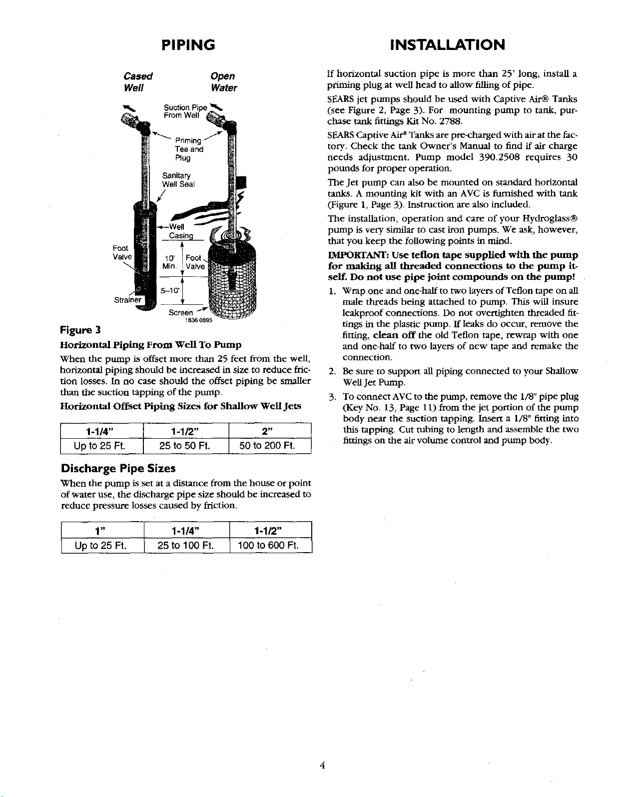
Cased Open
Well Water
Foot
Valve
Strainer
Screen
18360695
Figure 3
Horizontal Piping From well To Pump
When the pump is offset more than 25 feet from the well,
horizontal piping should be increased in size to reduce fric-
tion losses. In no case should the offset piping be smaller
than the suction tapping of the pump.
Horizontal Offset Piping Sizes for Shallow Well Jets
2 _
50 to 200 Ft.
t 1-1/4"
Up to 25 Ft.
1-1/2"
25 to 50 Ft.
ff horizontal suction pipe is more than 25' long, install a
priming plug at well head to allow filling of pipe.
SEARS jet pumps should be used vdth Captive Air® Tanks
(see Figure 2, Page 3). For mounting pump to tank, pur-
chase tank fittings Kit No. 2788.
SEARS Captive Air* Tanks are pre-charged with air at the fac-
tory. Check the tank Owner's Manual to find if air charge
needs adjustment. Pump model 390.2508 requires 30
pounds for proper operation.
The Jet pump can also be mounted on standard horizontal
tanks. A mounting kit with an AVC is furnished with tank
(Figure 1, Page 3). Instruction are also included.
The installation, operation and care of your Hydroglass®
pump is very similar to cast iron pumps. We ask, however,
that you keep the following points in mind.
IMPORTANT: Use teflon tape supplied with the pump
for making all threaded connections to the pump it-
self. Do not use pipe joint compounds on the pump!
1. Wrap one and one-half to two layers of Teflon tape on all
male threads being attached to pump. This vdll insure
leakproof connections. Do not overtighten threaded fiv
tings in the plastic pump. If leaks do occur, remove the
fitting, clean off the old Teflon tape, rewrap with one
and one-half to two Myers of new tape and remake the
connection.
2.
Be sure to support all piping connected to your Shallow
Well Jet Pump.
3.
To connect AVC to the pump, remove the 1/8" pipe plug
(Key No. 13, Page 11) from the jet portion of the pump
body near the suction tapping. Insert a 1/8" fitting into
this tapping. Cut tubing to length and assemble the two
fittings on the air volume control and pump body.
Discharge Pipe Sizes
When the pump is set at a distance from the house or point
of water use, the discharge pipe size should be increased to
reduce pressure losses caused by friction.
1" l 1-1/4" 1-1/2"
Up to 25 Ft. _ 25 to 100 Ft. 100 to 600 Ft.
ELECTRICAL
Disconnect power before working on pump, motor, pressure switch, or wiring.
Motor Switch Settings
If the motor can operate at either 115 or 230 volts, it is set
at the factory to 230 volts. Do not change motor voltage
setting if line voltage is 230 volts, or if you have a single
voltage motor.
NOTICE: Never wire a 115 volt motor to a 230 volt line.
Remove Hotor End Cover
Figure 4 - Removing Motor End Cover
You will need to remove the motor end cover to change
the voltage setting. The illustration above also shows the
pressure switch. If the power supply connection still
needs to be made, the pressure svdtch cover v/ill need to
be removed.
Your motor terminal board (located under the motor end
cover) should look like the one at right.
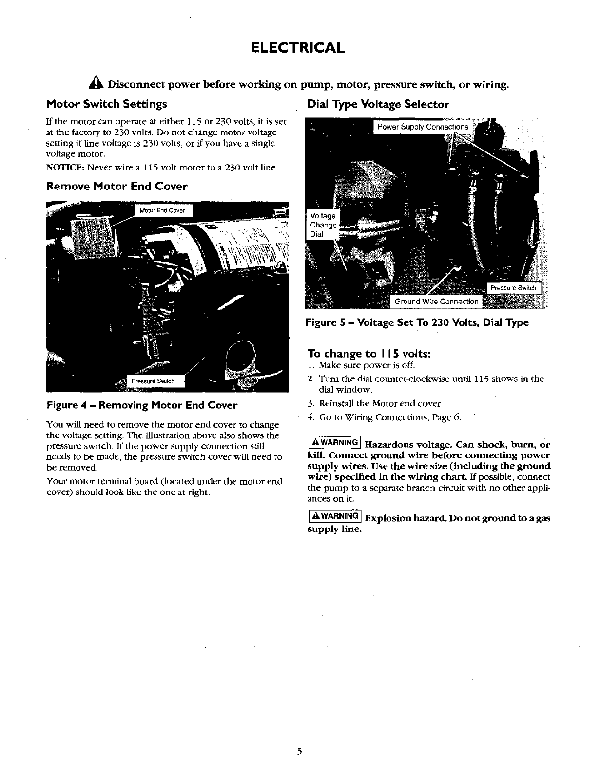
Dial Type Voltage Selector
Figure 5 - Voltage Set To 230 Volts, Dial Type
To change to I 15 volts:
1. Make sure power is off.
2. Turn the dial counter-clockwise until 115 shows in the
dial window.
3. Reinstall the Motor end cover
4. Go to Wiring Connections, Page 6.
I_,WARNING] Hazardous voltage. Can shock, burn, or
kill. Connect ground wire before connecting power
supply wires. Use the wire size (including the ground
wire) specified in the wiring chart. If possible, connect
the pump to a separate branch circuit with no other appli-
ances on it.
[_.WARNING] Explosion hazard. Do not ground to a gas
supply line.
 Loading...