

Craftsman 3902505 Owner’s Manual
SEARS
OWNER'S
MANUAL
MODEL NO.
390.2505
I:RI:IFTSMRN°
CAUTION:
Readand Follow
All Safety Rulesand
Operating Instructions
BeforeFirstUseof
ThisProduct.
Save ThisManual For
FutureReference.
Sears, Roebuck and Co., Hoffman Estates, IL 60179 U.S.A.
PRtNTED iN U.S.A. FormNo. F642-04071 (8/3/04)
SHALLOW WELL
JET PUMP
• Safety Instructions
• Installation
• Electrical
• Maintenance
• Repair Parts
CONTENTS
Introduction ............................................................... 2
Warranty ..................................................................... 2
Major System Components ........................................ 3
Installation .................................................................. 4
Electrical .................................................................. 5_5
Maintenance ............................................................ 7-8
Troubleshooting ......................................................... 9
Repair Parts ......................................................... 10-11
INTRODUCTION
Please read our instructions before installing and using
your pump. This will help you obtain the full benefits
of the quality and convenience built into this equip-
ment. It will also help you avoid any needless service
expense resulting from causes beyond our control
which are not covered by our w_ty.
RULES FOR SAFE INSTALLATION AND OPERATION
1. Read the Owners Manual and Rules for Safe
Operation and Installation Instructions carefufiy.
Failure to follow these Rules and Instructions could
cause serious bodily injury, and/or property damage.
2. Check your local electrical wiring codes before in-
stallation. If your local codes are not followed, your
pump will not work to its full rated capacity and
could present a fire hazard. If in doubt, contact your
local power company.
3. BE SURE your pump installation meets all local
plumbing, pump and well codes.
4. While installing your pump, always keep the well
covered to prevent leaves and foreign matter from
falling into the well, contaminating the water
and/or causing possible serious damage to the me-
chanical operation of the pump.
5. Always test the water from web for purity before
using. Check with local health department for test-
ing procedure.
6. Before instaUing or servicing your pump, BE SURE
pump power source is disconnected.
7. BE SURE your pump electrical circuit is properly
grounded.
8. Complete pump and piping system MUST be pre-
tected against below freezing temperature.
Allowing the pump or piping to freeze could cause
severe damage and voids the Warranty.
9. BE SURE the line voltage and frequency of the elec-
trical current supply agree with the motor wiring
as shown on motor nameplate.
10. The correct fusing and wiring sizing is essential to
proper motor operation. Use recommended fusing
and wire size data in the manual (Pages 5 and 6).
11. Pump water only with this pump.
12. Periodically inspect pump and system components.
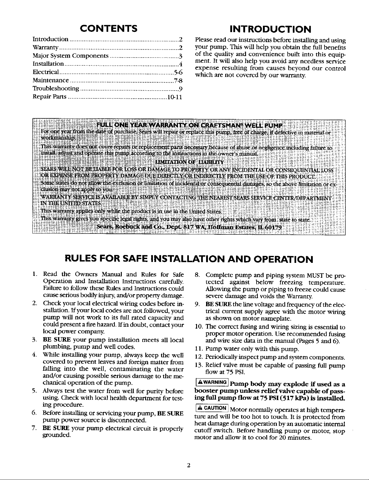
13. Relief valve must be capable of passing full pump
flow at 75 PSI.
[kWARNIN_ Pump body may explode if used as a
booster pump unless relief valve capable of pass-
ing full pump flow at 75 PSI (517 kPa) is installed.
[a_CAOTION]Motor normally operates at high tempera-
ture and will be too hot to touch. It is protected from
heat damage during operation by an automatic internal
cutoff switch. Before handling pump or motor, stop
motor and allow it to cool for 20 minutes.
2
MAJOR COMPONENTS AND WHAT THEY DO
Tank and Air Volume Control
The tank serves two functions. It provides a reservoir
of water, so that the pump doesn't need to start every
time water is drawn from a fixture in the house, and it
maintains a cushion of air under pressure.
When Captive Air* Tanks are used, no air volume con-
trol is necessary. This tank is precharged with air at the
factory.
When a Standard Tank is used, an air volume control
adds air to the tank when it is needed. See instructions
included with Air Volume Control for details on instal-
lation and operation.
Pressure Switch
The pressure switch provides automatic control.
Model No.
390.2505
When used with a Captive Air* Tank, the precharge
may need adjustment. See the Captive Air* Tank in-
structions for details.
Impeller and Jet
The impeller of the pump rotates with the motor shaft,
causing the water to fly out from its rim by centrifugal
force. The rotation of the impeller creates a partial vac-
uum which pulls in more water. Part of the water is di-
verted back to the jet where it passes through the
nozzle and venturi, reinforcing the vacuum to draw in
more water and delivering it at a high velocity to the
impeller.
Because of the shallow setting, the partial vacuum cre-
ated by the pump is sufficient to pull water to the
pump, therefore, the jet assembly is attached directly
to the pump.
Piping In The Well
A Shallow well jet pump can be installed on a dug well,
drilled well or with a driven point. SEARS shallow well jet
pumps have a built-in check valve. In a dug or cased well,
a foot valve and strainer is recommended and should be
installed 5 to 10 feet below the lowest level to which the
water will drop while pump is operating (pumping water
level), See Figure 3, Page 4. Your well driller can furnish
this information. The strainer should not be too close to
the bottom, or sediment may clog it. Before installing foot
valve, check to see that it works freely.
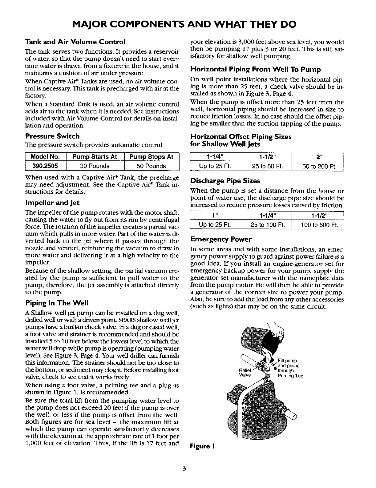
When using a foot valve, a priming tee and a plug as
shown in Figure 1, is recommended.
Be sure the total lift from the pumping water level to
the pump does not exceed 20 feet if the pump is over
the well, or less if the pump is offset from the well.
Both figures arc for sea level - the maximum lift at
which the pump can operate satisfactorily decreases
with the elevation at the approximate rate of 1 foot per
1,000 feet of elevation. Thus, if the lift is 17 feet and
Pump Starts At
30 Pounds
Pump Stops At
50 Pounds
your elevation is 3,000 feet above sea level, you would
then be pumping 17 plus 3 or 20 feet. This is still sat-
isfactory for shallow well pumping.
Horizontal Piping From Well To Pump
On well point installations where the horizontal pip-
ing is more than 25 feet, a check valve should be in-
stalled as shown in Figure 3, Page 4.
When the pump is offset more than 25 feet from the
well, horizontal piping should be increased in size to
reduce friction losses. In no case should the offset pip-
ing be smaller than the suction tapping of the pump.
Horizontal Offset Piping Sizes
for Shallow Well Jets
1-1/4" 1-1/2" 2"
Up to 25 Ft. 25 to 50 Ft. 50 to 200 Ft.
Discharge Pipe Sizes
When the pump is set a distance from the house or
point of water use, the discharge pipe size should be
Increased to reduce pressure losses caused by friction.
1" 1-1/4" 1-1/2"
Up to 25 Ft. 25 to 100 Ft. t 00 to 600 Ft.
Emergency Power
In some areas and with some installations, an emer-
gency power supply to guard against power failure is a
good idea. If you install an engine-generator set for
emergency backup power for your pump, supply the
generator set manufacturer with the nameplate data
from the pump motor. He will then be able to provide
a generator of the correct size to power your pump.
Also, be sure to add the load from any other accessories
(such as lights) that may be on the same circuit.
Relief "
Valve Priming Tee
Figure I
and piping
INSTALLATION
ReliefValve
Plug
To Household
Water System Built-in
Switch
Tank
Check Valve
Adapter
From
Weft
Plastic
Pipe
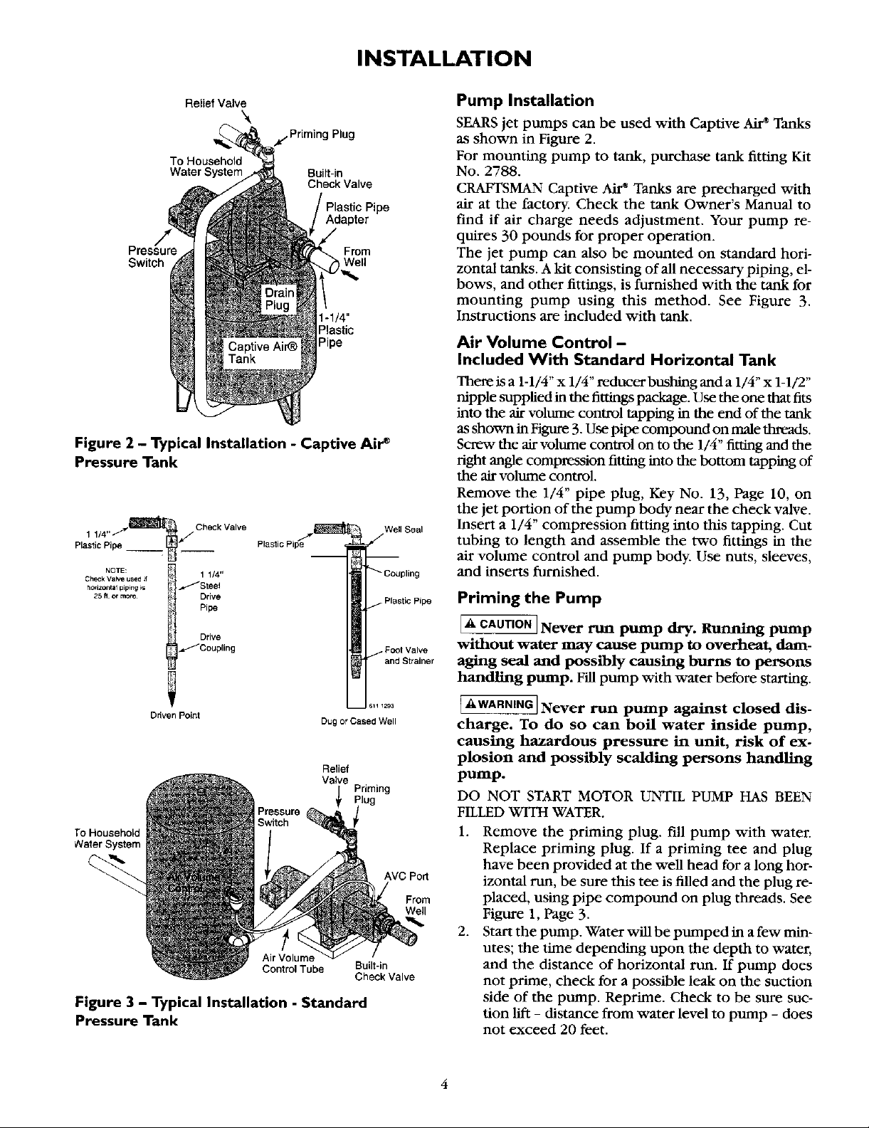
Figure 2 - Typical Installation - Captive Air e
Pressure Tank
Plastic P
NOTE: _ 1 1/4"
Check Va_e used if
h°dz°ntal piping is _t /Stee_
25. o_more _{ Drive
_'Coupling
o.ockvo,vo
Pipe
Drive
Well Seal
Foot Valve
Pump Installation
SEARS jet pumps can be used with Captive _ Tanks
as shown in Figure 2.
For mounting pump to tank, purchase tank fitting Kit
No. 2788.
CRAFTSMAN Captive Air* Tanks are precharged with
air at the factory. Check the tank Owner's Manual to
find if air charge needs adjustment. Your pump re-
quires 30 pounds for proper operation.
The jet pump can also be mounted on standard hori-
zontal tanks. A kit consisting of all necessary piping, el-
bows, and other fittings, is furnished with the tank for
mounting pump using this method. See Figure 3.
Instructions are included with tank.
Air Volume Control -
Included With Standard Horizontal Tank
There is a 1-1/4" x 1/4" reducer bushing and a 1/4" x 1-1/2"
nipple supplied in the fittings package. Use the one that fits
into the air volume control tapping in the end of the tank
as shown in Figure 3. Use pipe compound on male threads.
Screw the air volume control on to the 1/4" fitting and the
right angle compression fitting into the bottom tapping of
the air volume control.
Remove the 1/4" pipe plug, Key No. 13, Page 10, on
the jet portion of the pump body near the check valve.
Insert a 1/4" compression fitting into this tapping. Cut
tubing to length and assemble the two fittings in the
air volume control and pump body. Use nuts, sleeves,
and inserts furnished.
Priming the Pump
I_' CAUTIONI Never run pump dry. Running pump
without water may cause pump to overheat, dam-
aging seal and possibly causing burns to persons
handling pump. Fill pump with water before starting.
Ddven Point
To Household
Water System
Air Volume
Control Tube Built-in
Dug or Cased Well
Relief
Valve
Figure 3 - Typical Installation - Standard
Pressure Tank
Priming
AVC Port
Check Valve
From
Well
[AWA_ Never run pmnp against closed dis-
charge. To do so can boil water inside pump,
causing hazardous pressure in unit, risk of ex-
plosion and possibly scalding persons handling
pump.
DO NOT START MOTOR UNTIL PUMP HAS BEEN
FILLED WITH WATER.
1. Remove the priming plug. fill pump with water.
Replace priming plug. If a priming tee and plug
have been provided at the well head for a long hor-
izontal run, be sure this tee is filled and the plug re-
placed, using pipe compound on plug threads. See
Figure 1, Page 3.
2. Start the pump. Water win be pumped in a few min-
utes; the time depending upon the depth to water,
and the distance of horizontal run. If pump does
not prime, check for a possible leak on the suction
side of the pump. Reprime. Check to be sure suc-
tion lift - distance from water level to pump - does
not exceed 20 feet.
4
 Loading...