

Craftsman 351.275210 Operator's Manual

Operator's Manual
CRAFTSMAN®
12Y2''
PLANER/MOLDER
Model
351.275210
No.
CAUTION: Read and follow
all Safety Rules and Operating
Instructions before First Use
of this Product.
Sears Canada Inc., Toronto, Ontario MSB
8507.03 Draft (08/10/97)
288
TABLE
OF
CONTENTS
Warranty
..................................
2
Safety Rules
..............................
2-3
Assembly
...............
..
............
....
. 3
Installation . .
.............................
3-5
Operation
...........
.
.............
.
.....
5-12
Maintenance . . . . . . . . . . . . . . . . . . . . . . . . . . . . . . 12
Troubleshooting
.... , .......................
13
Parts Illustration and List
......
....
........
14-19
WAR.RANTY
FULL ONE YEAR WARRANTY ON
CRAFTSMAN 12%" PLANER/MOLDER
If within one full year from the date
of
purchase, this
Craftsman planer/molder
fails due to a defect
in
materi-
al
or
workmanship, Sears will repair it, free
of
charge.
Warranty service is available
by
contacting Sears. This
warranty is in addition
to
any statutory warranty.
If this planer/molder is used for commercial purposes,
this warranty applies for only
90 days from the date
of
purchase.
Sears Canada, Inc., Toronto, Ontario
M58
288
SAFETY
RULES
WARNING: For your own safety, read all of the
instructions and precautionsbefore operating
tool.
CAUTION: Always follow proper operating procedures
as defined
in
this manual even if you are familiar with
use
of
this
or
similar tools. Remember that being care-
less for even a fraction
of
a second can result in severe
personal injury.
BE PREPARED FOR JOB
• Wear proper apparel. Do not wear loose clothing,
gloves, neckties, rings, bracelets or other jewelry
which may get caught in moving parts
of
machine.
• Wear protective hair covering to contain long hair.
• Wear safety shoes with non-slip soles.
• Wear safety glasses complying with United States
ANSI Z87.1. Everyday glasses have only impact
resistant lenses. They are
NOT safety glasses.
• Wear face mask
or
dust mask if operation is dusty.
• Be alert and think clearly. Never operate power tools
when tired, intoxicated or when taking medications
that cause drowsiness.
2
PREPARE WORK AREA FOR JOB
• Keep work area clean. Cluttered work areas invite
accidents.
• Do not use power tools in dangerous env ironments.
Do not use power tools
in
damp
or
wet locations. Do
not expose power tools to rain.
• Work area should be properly lighted.
• Proper electrical receptacle should be available for
tool. Three prong plug should be plugged directly
into properly grounded, three-prong receptacle.
• Extension cords should have a grounding prong and
the three wires
of
the extension cord should be of
the correct gauge.
• Keep visitors at a safe distance from work area.
• Keep children out of workplace. Make workshop childproof. Use padlocks, master switches or remove switch
keys
to
prevent any unintentional use
of
power tools.
TOOL SHOULD
BE
MAINTAINED
• Always unplug tool prior to inspection.
• Consult manual for specific maintaining and adjusting procedures.
• Keep tool lubricated and clean for safest operation.
• Remove adjusting tools. Form habit of checking to
see that adjusting tools are removed before switching machine on.
• Keep all parts
in
working order. Check to determine
that the guard or other parts will operate properly
and perform the ir intended function.
• Check for damaged parts. Check for alignment of
moving parts, bi
nd
ing, breakage, mounting and any
other condition that may affect a tool's operation.
• A guard
or
other part that is damaged should be
properly repaired or rep laced. Do not perfo
rm
makeshift repairs. (Use parts list provided to order
replacement parts.)
KNOW HOW TO USE TOOL
• Use right tool for job. Do not force tool or attachment
to do a job for 'which it was not designed.
• Disconnect tool when changing blades.
• Avoid accidental start-up. Make sure that the switch
is
in
the "off" position before plugging
in.
• Do not force tool. It will work most efficiently at the
rate for which it was designed.
• Keep hands away from moving parts and cutting
surfaces.
• Never leave tool running unattended. Turn the power
off
and do not leave tool until
it
comes to a complete
stop.
• Do not overreach. Keep proper footing and balance.
• Never stand on tool. Serious injury could occur if tool
is
tipped or if blade is unintentionally contacted.
• Know your tool. Learn the tool's operation, applica-
tion and specific limitation
s.

• Use recommended accessories (refer to page 17).
Use
of
improper accessories may cause risk of
injury to persons.
• Handle workpiece correctly. Protect hands from possible
injury.
• Turn machine off if it jams. Knife or bit jams when it
digs too deeply into workpiece. (Motor force keeps it
stuck
in
the work.)
• Always keep drive. cutterhead and knife guards in
place and
in
proper operating condition.
• Feed work into knife or cutter against direction of
rotation.
CAUTION: Think safety! Safety is a combination
of
operator common sense and alertness at all times
when tool is being used.
WARNING:
Do
not attempt to operate tool until
it
is
completely assembled according to the instructions.
ASSEMBLY
'
Refer to Figures 15 and 16, pages 16 and 18.
The planer/molder
is
shipped assembled except for the
handwheel and handle (Figure
16,
Key Nos. 22 and 24).
INSTALL HANDWHEEL
AND
HANDLE
Refer to Figure 16, page 18.
• Handwheel (Key
No.
22) must be installed to the left
side
of
the planer/molder.
• Align handle (Key No. 24) with the hole on the rim
of
the handwheel.
• Insert handle
screw (Key
No.
23) into handle and
tighten to secure.
• Slide handwheel onto crank elevation screw (Key
No.
19) so that the spring pin (Key
No.
21) on the
crank elevation screw
is
positioned between the
groove
in
the handwheel.
REMOVE CAPS
Refer to Figure 15, page 16.
The planer/molder is shipped with caps (Key
No.
13) on
the threaded shafts (Key
No.
11) to avoid damage to
shafts during shipping and handling.
• Unscrew and remove caps before turning the tool on.
• Save caps for future use.
MOUNT PLANER
TO
WORK
SURFACE
Refer to Figure
1.
• Planer is designed to be portable so
it
can be moved
to job site, but
should be mounted to stable, level
bench
or
table. See Recommended Accessories,
page
17.
3
MOUNTING
INSTRUCTIONS FOR
OPTIONAL
STAND
MODEL
22250
Refer to Figure
1.
Material List
•
Y2
x 15 x 22" particle board (not supplied)
• Four
14-20
x 1
1.1.1''
Bolts wi
th
washers and nuts (not
supplied) for mounting board to
Multi-Purpose Stand.
• Four 8-1.25 x 30mm bolts with washers (supplied
with planer/molder) for mounting planer/molder
to
board.
A mounting board is needed when mounting
planer/molder
to
Sears Multi-Purpose Stand Model
22250. The mounting board is made from
W'
thick ply-
wood or particle board.
• Cut and drill the board using drawing. The 1 0" diameter hole in the center is used for ventilation only.
•
Secure the mounting board to the stand top first,
using four
14"
bolts, washers and nuts (not provided).
be sure board is centered on stand top and bolted
securely.
• Mount the planer/molder to the mounting board
using the four 8-1.25 x 30mm bolts with washers.
Thread the
bolts through the mounting board and
into the base casting from underneath the board.
r---H--
0 0
0
I
%"
6
~'
--+---
9'Ae"
...._-------2
2"
Figure 1 - Mount Planer/Molder to Optional Multi-Purpose
Stand Model No. 22250
INSTALLATION
POWER
SOURCE
WARNING: Do not connect planer/molder to the power
source until all assembly steps have been completed.
The motor is designed for operation on the voltage and
frequency specified. Normal loa
ds
will be handled safe-
ly
on voltages not more than 1
0%
above
or
below specified voltage. Running the unit on voltages which are not
within range may cause overheating and motor burnout. Heavy loads require that voltage
at
motor terminals
be
no
less than the voltage specified on nameplate.
• Power supply to t
he
motor is contro lled by a rocker
switch. Removing the rocker switch
will lock the unit
and prevent unauthorized us
e.
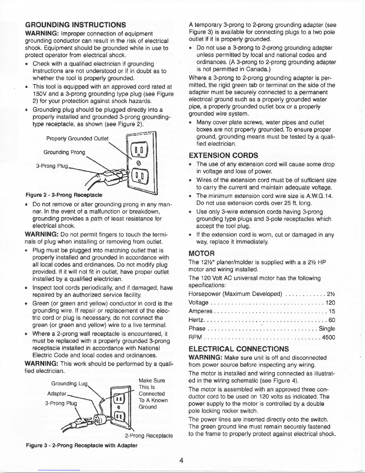
GROUNDING INSTRUCTIONS
WARNING:
Improper connection of equipment
grounding conductor can result in the risk of electrical
shock. Equipment should be grounded while
in
use to
protect operator from electrical shock.
• Check with a qualified electrician if grounding
instructions are not understood or if
in
doubt as to
whether the tool is properly grounded.
• This tool is equipped with
an
approved cord rated at
150V and a 3-prong grounding type plug (see Figure
2) for your protection against shock hazards.
• Grounding plug should be plugged directly into a
properly installed and grounded 3-prong grounding-
type receptacle, as shown (see Figure 2).
Properly Grounded Outlet
Grounding Prong
3-Prong
Plug
Figure 2 - 3-Prong Receptacle
•
Do
not remove
or
alter grounding prong
in
any man-
ner.
In
the event of a malfunction
or
breakdown,
grounding provides a path of least resistance for
electrical shock.
WARNING:
Do
not permit fingers to touch the termi-
nals
of
plug when installing or removing from outlet.
• Plug must be plugged into matching outlet that is
properly installed and grounded in accordance with
all local codes and ordinances.
Do
not modify plug
provided.
If it will not fit in outlet, have proper outlet
installed by a qualified electrician.
• Inspect tool cords periodically, and if damaged, have
repaired by
an
authorized service facility.
• Green (or green and yellow) conductor
in
cord is the
grounding wire.
If repair or replacement of the elec-
tric cord or plug is necessary,
do
not conneCt the
green (or green and yellow) wire to a live terminal.
• Where a 2-prong wall receptacle is encountered,
it
must be replaced with a properly grounded 3-prong
receptacle installed in accordance with National
Electric Code and local codes and ordinances.
WARNING:
This work should be performed by a quali-
fied electrician.
Grounding Lug
Make
Sure
This
IS
Connected
To
A Known
Ground
2-Prong Receptacle
Figure
3 - 2-Prong Receptacle with Adapter
4
A temporary 3-prong to 2-prong grounding adapter (see
Figure
3)
is available for connecting plugs to a two pole
outlet if it is properly grounded.
•
Do
not use a 3-prong to 2-prong grounding adapter
unless permitted by local and national codes and
ordinances. (A 3-prong to 2-p
ro
ng grounding adapter
is not permitted
in
Canada.)
Where a 3-prong to 2-prong ground ing adapter is
per-
mitted, the rigid green tab
or
terminal on the side of the
adapter must be securely connected to a permanent
electrical ground such as a properly grounded water
pipe, a properly grounded outlet box or a properly
grounded wire system.
• Many cover plate screws, water pipes and outlet
boxes are not properly grounded.
To
ensure proper
ground, grounding means must be tested by a
quali-
fied electrician.
EXTENSION CORDS
• The use of any extension cord will cause some drop
in voltage and loss of power.
• Wires of the extension cord must be of sufficient size
to
carry the current and maintain adequate voltage.
• The minimum extension cord wire size
is
A.W.G.14.
Do not use extension cords over 25 ft. long.
• Use only 3-wire extension cords having 3-prong
grounding type plugs and 3-pole receptacles which
accept the tool plug.
• If the extension cord is worn, cut or damaged
in
any
way,
replace it immediately.
MOTOR
The 12W' planer/molder is supplied with a a
2%
HP
motor and wiring installed.
The
120 Volt AC universal motor has the following
specifications:
Horsepower (Maximum Developed) .
...........
2%
Voltage . . . . . . . . . . . . . . . . . . . . . . . . . . . . . . . . . 120
Amperes
.....
. .
......
...........
.
........ 15
Hertz .
....
. .
.. ................
.
.......
.
..
60
Phase
....
..
.........
."
. .
........
......
Single
RPM
.....
.......
.
......
..
. .
...
......
. . 4500
ELECTRICAL CONNECTIONS
WARNING:
Make sure unit
is
ott and disconnected
from power source before inspecting any wiring.
The motor is installed and wiring connected as
illustrat-
ed in the wiring schematic (see Figure 4
).
The motor is assembled with
an
approved three con-
duc
tor
cord to
be
used on 120 volts as indicated. The
power supply to the motor is controlled by a double
pole locking rocker switch.
The power lines are inserted directly onto the switch.
The green ground
line must rema
in
securely fastened
to the frame to properly protect against electrical shock.
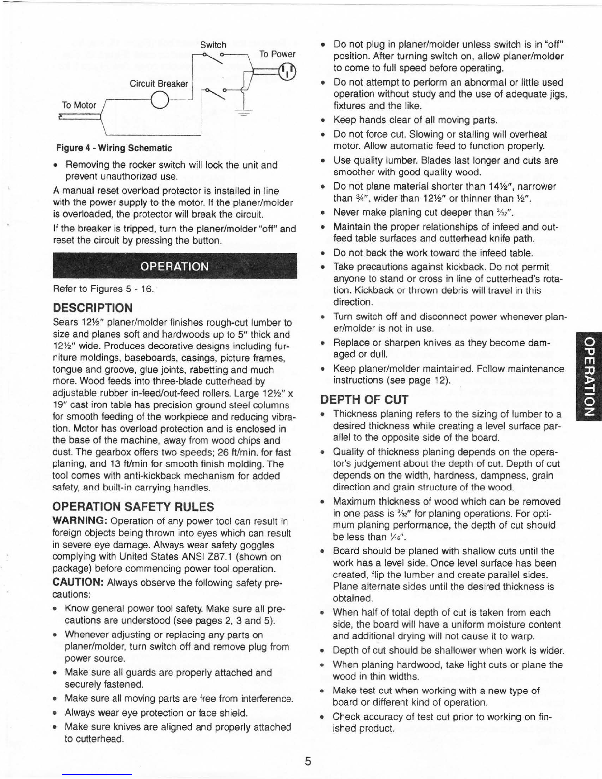
Switch
To
Motor
Figure 4 -Wiring Schematic
• Removing the rocker switch will lock the unit and
prevent unauthorized use.
A manual reset overload protector is installed in line
with the power supply to the motor.
If the planer/molder
is overloaded, the protector
will break the circuit.
If the breaker is tripped, turn the planer/molder "off" and
reset the circuit
by
pressing the button.
OPERATION
Refer to Figures 5 - 16.
DESCRIPTION
Sears 12W' planer/molder finishes rough-cut lumber to
size and planes soft and hardwoods up to
5" thick and
12W' wide. Produces decorative designs including furniture moldings, baseboards, casings, picture frames,
tongue and groove, glue joints, rabetting and much
more. Wood feeds into three-blade cutterhead by
adjustable rubber in-feed/out-feed rollers. Large
12W' x
19" cast iron table has precision ground steel columns
for smooth feeding of the workpiece and reducing vibration. Motor has overload protection and is enclosed
in
the base of the machine, away from wood chips and
dust. The gearbox offers two speeds; 26
ftlmin. for fast
planing, and
13ft/min
for smooth finish molding. The
tool comes with anti-kickback mechanism for added
safety, and
bu
ilt-in carrying handles.
OPERATION SAFETY RULES
WARNING: Operation of any power tool can result
in
foreign objects being thrown into eyes which can result
in severe eye damage. Always wear safety goggles
complying with United States
ANSI Z87.1 (shown on
package) before commencing power tool operation.
CAUTION: Always observe the following safety pre-
cautions:
• Know general power tool safety. Make sure all pre-
cautions are understood (see pages 2, 3 and 5).
• Whenever adjusting
or
replacing any parts on
planer/molder, turn switch off and remove plug from
power source.
• Make sure all guards are properly attached and
securely fastened.
• Make sure all moving parts are free from interference.
• Always wear eye protection or face shield.
• Make sure knives are aligned and properly attached
to cutterhead.
5
• Do not plug in planer/molder unless switch is in "o ff"
position. After turning switch on, allow planer/molder
to come to
full speed before operating.
• Do not attempt to perform an abnormal
or
little used
operation without study and the use
of
adequate jigs,
fixtures and the like.
• Keep hands clear
of
all moving parts.
• Do not force cut. Slowing or stalling will overheat
motor.
Allow automatic feed to function properly.
• Use quality lumber. Blades last longer and cuts are
smoother with good quality wood.
• Do not plane material shorter than
14Y2'',
narrower
than
3
.4"
, wider than 12W'
or
thinner than W'.
• Never make planing cut deeper than % ".
•
Maintain the proper relationships of infeed and outfeed table surfaces and cutterhead knife path.
•
Do
not back the work toward the infeed table.
• Take precautions against kickback. Do not permit
anyone
to
stand or cross in line of cutterhead's rota-
tion . Kickback
or
thrown debris will travel in this
direction.
• Turn switch off and disconnect power whenever planer/molder is not
in
use.
• Replace
or
sharpen knives as they become dam-
aged
or
dull.
•
Keep planer/molder maintained. Follow maintenance
instructions (see page 12}.
DEPTH
OF
CUT
• Thickness planing refers to the sizing of lumber to a
desired thickness while creating a
level surface par-
allel
to
the opposite side of the board.
• Quality
of
thickness planing depends on the operator's judgement about the depth of cut. Depth of cut
depends on the width, hardness, dampness, grain
direction and grain structure of the wood.
• Maximum thickness of wood which can be removed
in
one pass is
%2''
for planing operations . For optimum planing performance, the depth of cut should
be
less than
~6,.
• Board should be planed with shallow cuts until the
work has a
level side. Once level surface has been
created, flip the lumber and create
parallel sides.
Plane alternate sides until the desired thickness is
obtained.
• When half of total depth of cut is taken from each
side, the board
will have a uniform moisture content
and additional drying
will not cause
it
to warp.
• Depth of cut should be shallower when work is wider.
• When planing hardwood, take light cuts or plane the
wood in thin widths.
• Make test cut when working with a new type
of
board or different kind
of
operation.
• Check accuracy of test cut prior to working
on
fin-
ished product.

ADJUSTING THE DEPTH
Refer
to
Figure 16, page 18.
Board thickness which
indicated by either scale (Key No.4) on the side.
Thickness is adjusted
No. 22) clockwise to raise the knife height.
To reduce the knife height, rotate the handwheel counterclockwise.
• Do not set knife below '
which is less than a
• Knife height will be moved
revolution of the
Make a test cut on a piece
thickness produced.
The planer/molder will produce uneven depth of cut
(tapered cut)
To
restore parallelism of the cutterhead with the table:
• Clamp a vise plier on the left side
No.6)
• Loosen set screws (Key No. 51) and disengage right
bevel gear (Key No. 1
No. 18).
• Slowly rotate
Rotate clockwise to raise table, counterclockwise to
lower table. Table will be moved
turn
• After mov ing table the required distance, make sure
beveled gears (Key Nos. 1
and secured with set screws.
• Release and remove the vise plier
Make a test cut to make sure the adjustment was
•
appropriate.
• Add grease to bevel gears if necessary.
When the depth
loosen the pan head screw (Key.
indicator (Key No. 29) to show the thickness produced.
Make sure that the indicator is positioned correctly.
if
the cutterhead is not parallel with the table.
next to the bevel gear
of
the beveled gear by one tooth.
t~e
by
rotating the handwheel (Key
W'
handwheel.
O)
ha~dwheel
of
cut adjustment is operating correctly,
OF
CUT
planer/molder will produce
o/32".
Do not plane a board
thick.
Y.s"
with every complete
of
wood and measure the
of
the shaft (Key
(Key.
No.
10).
on the elevation screw (Key
to raise or lower the table.
by
.004" with every
0 and 12) are engaged
No.
28) and set the
is
TABLE HEIGHT ADJUSTMENT
Refer to Figure 16, page 18.
• The depth
raising or lowering the table .
• Rotate the handwheel (Key
the table
• The scale and indicator (Key Nos. 4 and 29) can be
used when adjusting the table height.
of
cut
of
the planer/molder
to
the desired position.
No.
22) to raise
is
adjusted by
or
lower
FEED RATE ADJUSTMENT
Refer to Figures 5 and 15, pages 6 and 16.
The planer/molder has a 2-speed gearbox that feeds
the workpiece
surface finish when molding or planing and
faster planing.
• Be sure to unplug the planer/molder from power source
and turn planer/molder
rate.
at
13 feet per minute (FPM) for improved
26
FPM for
OFF before adjusting the feed
• Remove the socket head bolt (Figure 15, Key No.
33) that secures the gearbox cover (Figure
No.
35), remove the gearbox cover. See Figure 5 for
the proper location of the gears.
21T
40T
MOLDING
13
FPM
Figure 5 - Gear Chart
The planer/molder is assembled with the gears for 13
FPM. Both planing and molding can be done at this set-
up. For the increased feed rate - 26 FPM, the gears
have to be changed. Gears for 26
ware bag.
To
change gears:
• Loosen and remove nylon insert locknuts (Figure
Key No. 28).
• Slide two screwdrivers, one on either side of the 40T
molding gear (Figure 15, Key No.
• Gently push the screwdrivers and slide gear off the
gear shaft (Figure 15, Key No. 29).
• Leave the key (Figure
• Remove the 21T molding gear (Figure
• Position the gears for 26 FPM on the gear shaft,
aligning the keyway.
• Gently push it into place.
• Replace and tighten nylon insert locknuts
PLANING
26
FPM
FPM are in the hard-
31
15,
Key
No.
27)
).
llT
]11
in
the gear
15,
Key
15
, Key
shaft.
No.
15,
26).
V-BELT ADJUSTMENT
Refer to Figures 14, 15 and 16, pages 14, 16 and 18.
Inadequate tension
will cause the belt to slip from the motor pulley (Figure
14, Key
To adju st
• Loosen and remo
• Remo
• Loosen two socket head bolts (Figure 16, Key
• Tighten two socket head bolts (Figure 16, Key No.
• Tighten two socket head bolts (Figure 16,
• Replace cover and tighten four bolts (Figure 16,
No.9)
V-Belt tension:
16, Key
that
48) that go into the indent on tension plate to tension
belt. Belt is tensioned properly when moderate finger
pressure applied to the midpoint of
deflection.
that go through the tension plat
Nos. 2 and 5).
No.
ve
cover.
go
through the tension plate (Figure 16,
in
the V-Belt (Figure 15, Key No. 54)
or drive pulley (Figure 15, Key
ve
four socket head bolts (Figure
5)
on
cover (Figure 16, Key No.
belt produces W'
Key
e.
No.
Key
2)
No.
53).
No.
No.
48)
39)
48)
Key
.
6
 Loading...