

Craftsman 351.252741, 351.252181, 351.253351 Operator's Manual
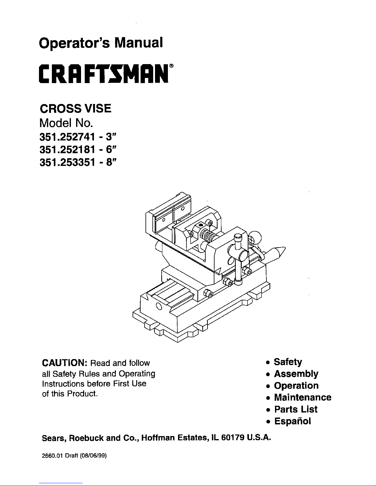
Operator's Manual
CRRFT. RN °
CROSS VISE
Model No.
351.252741 -3"
351.252181 - 6"
351.253351 -8"
CAUTION: Read and follow
all Safety Rules and Operating
Instructions before First Use
of this Product.
• Safety
• Assembly
• Operation
• Maintenance
• Parts List
• Espa_ol
Sears, Roebuck and Co., Hoffman Estates, IL 60179 U.S.A.
2660.01 Draft (08/06/99)
Warranty....................................... 2
Safety Rules.................................... 2
Assembly ...................................... 2
Operation ...................................... 2
Maintenance.................................... 3
Parts Illustrationand List ......................... 4-5
Espafiol ...................................... 6-7
FULL ONE YEAR WARRANTY ON CRAFTSMAN
CROSS VISES
Ifwithin one full year from the date of purchase, this
Craftsman Cross Vise fails due to a defect in materfel or
workmanship, Sears will repairitfree of charge.
Warranty service is available by simply returningthe Cross
Vise to the nearest Sears Store or Service Center throughout
the United States.
This warranty givesyou specificlegal rightsand youmay
have other rightswhich vary from state to state.
Sears, Roebuck and Co., Dept 817WA, Hoffman Estates, IL
60179
• Understand and obey all safety instructionssuppliedwith
drillpress, mill,or other machines on which vise is used.
• Bolt orclamp vise to work surface in at least two mounting
locations usingmounting flanges provided on base.
• Be sure workpiece isclamped securely between jaws
before starting machining operation.
• Do not over tighten--vise can develop a large damping
force.Use only force which is needed.
• Do not pound or hammer on workpiece.This vise is
designed to clamp the workpiece in a desired positionfor
machining operations only.
MODEL 252741, 3" VISE
Refer to Figure 1.
• Mount crank handles (Fig. 1, No. 12) to longitudinaland
cressfeed leadscrews (Fig. 1, Nos. 9 and 23) using acorn
nuts (Fig. 1, No. 13).
• This vise is shipped with a protective coating.This coating
should be removedbefore operation. Remove protective
coating with penetratingoil.
MODELS 252181 AND 253351,6" AND 8" VISES
Refer to Figure 1.
• Thread movablejaw leadscrew (Fig. 1, No. 14) through end
ofbody (Fig. 1, No. 16) and into holein movablejaw (Fig. 1,
No. 18).
• Secure with dog point set screw (Fig. 1, No. 19)
• Mount crank handles (Fig. 1, No. 12) to longitudinaland
crossfeed leadscrews (Fig. 1, Nos. 9 and 23) usingacorn
nuts (Fig. 1, No. 13).
• This vise is shipped with a protectivecoating. This coating
should be removed before operation.Remove protective
coatingwithpenetrating oil.
2
DESCRIPTION
Cross Vises travel ontwo separate axes_ongitudinal and
crossfeed, to permit accurate positioningof workpiece. Body,
saddle, base and jaws are made ofhigh strength cast iron.
Vise feadserew, longitudinaland crossfeed leadsorews are
precisfenground carbon steel.A prismaticjaw isprovided for
clamping roundstock.
Refer to Figure 1.
• Mount vise towork surface indesired location by securing at
least two mounting flanges located on base (Fig. 1, No. 1).
• Move saddle (Fig. 1, No. 3) by rotating longitudinal crank
handle (Fig. 1, No. 12). Tighten center set screw (Fig. 1,
No.6) to secure position.
• Move body to desired position by rotating crossfeed crank
handle (Fig. 1, No. 12). Tighten center set screw (Fig. 1,
No. 6) to secure position.
• Open jaws of vise. Place workpiece between jaws in
desired position. Rotate movable jaw leadscrew (Fig. 1, No.
14) to secure workpiese between jaws. Be sure workpiece
is secure in vise before starting machining operation.
SPECIFICATIONS
Longitudinaltravel (left to right).............. 5" (252741)
..................................... 8" (252180)
..................................... 8" (253351)
Cress travel (frontto back) ................. 5" (252741)
..................................... 8" (252180)
..................................... 8" (253351)
Jaw Width.............................. 3_ (252741)
..................................... 6" (252180)
..................................... 8" (253351)
Maximum Jaw Opening ................... 3" (252741)
..................................... 6" (252180)
..................................... 6" (253351)
Value of One Division ................ 0.0039" (252741)
................................. 0.0039"(252180)
................................. 0,0039" (253351)
Cross Travelper One Revolution........ 0.1181" (252741)
................................. 0.1575" (252180)
................................. 0.1575"(253351)
LongitudinalTravelper One Revolution... 0.1181" (252741)
................................. 0.1575" (252180)
................................. 0.1575"(253351)
MOUNTING PRISMATIC JAW
One prismatic jaw is provided. This prismatic jaw can be sub-
stitutedfor either flat jaw plate.
• Attach prismaticjawto work on roundstock. Deep V-slots
allow both horizontaland verticaldamping.
• Remove jaw plate by unscrewing socket head bolts (Fig. 1,
No. 17).
• Switch jaw plates and securely fasten prismatic jaw to vise,
using socket head bolts (Fig. 1, No. 17).
Particles of metal or wood can damage machined surfaces,
causing difficultor inaccurate operation.
• Keep machined surfaces and all moving parts clean and
free of dirt, chips and foreign materials.
• Keep machined surfaces and leadscrews lubricated with
medium weight machine oil.
GIB ADJUSTMENT
Refer to Figure 1.
• Adjustgibs (Fig. 1, No. 4) by tighteningthe set screws (Fig.
1, No. 6) at each end of the gibs.
• Adjustthe screws untila slight drag is felt when rotatingthe
crank handles (Fig. 1, No. 12). Secure screws by tightening
nuts(Fig. 1, No. 5).
3
 Loading...