

Page 1

Operator’s Manual
CRflFTSMHlF
Wall Mount
SHOP DUST COLLECTION SYSTEM
Model No.
351.223130
CAUTION: Read and follow
all Safety Rules and Operating
Instructions before First Use
of this Product.
Sears, Roebuck and Co., Hoffman Estates, IL 60179 U.S.A.
www.sears.com/craftsman
23961.01 Draft (06/02/06)
Safety Rules
Operation
Maintenance
Parts List
Español
Page 2

TABLE OF CONTENTS
Warranty...................................................................................................2
Safety Rules.............................................................................................2
Unpacking................................................................................................ 2
Assembly...............................................................................................2-3
Operation...............................................................................................3-4
Maintenance ............................................................................................4
Parts Illustration and List
Español................................................................................................. 5-7
.......................................................................
4
WARRANTY
ONE-YEAR FULL WARRANTY ON CRAFTSMAN TOOL
If this Craftsman tool fails due to a defect in material or
workmanship within one year from the date of purchase CALL
1-800-4-MY-HOME® TO ARRANGE FOR FREE REPAIR.
If this tool is used for commercial or rental purposes, this war
ranty will apply for oniy ninety days from the date of purchase.
This warranty applies oniy while this tool is in the United
States.
This warranty gives you specific legal rights and you may also
have other rights, which vary, from state to state.
Sears, Roebuck and Co., Dept. 817WA, Hoffman Estates,
IL 60179
SAFETY RULES
DANGER: Do not use this dust collection system in a flam
mable or explosive atmosphere. Do not use to collect metal
shavings or dust. Consult National Fire Protection Association
(NFPA) standards before setting up a dust collection system,
especially NFPA 664.
WARNING: For your own safety read all of the instructions
and precautions before operating tool.
WARNING: For your own safety read all of the instructions
and precautions for any dust collector used with this system.
CAUTION: Always follow proper operating procedures as
defined in this manual even if you are familiar with use of this
or similar tools. Remember that being careless for even a
fraction of a second can result in severe personal injury.
BE PREPARED FOR JOB
• Wear proper apparel. Do not wear loose clothing, gloves,
neckties, rings, bracelets or other jewelry which may get
caught in moving parts of machine.
• Wear protective hair covering to contain long hair.
• Wear safety shoes with non-slip soles.
• Wear safety glasses complying with United States ANSI
Z87.1. Everyday glasses have only impact resistant lens
es. They are NOT safety glasses.
• Wear face mask or dust mask if operation is dusty.
• Be alert and think clearly. Never operate power tools when
tired, intoxicated or when taking medications that cause
drowsiness.
PREPARE WORK AREA FOR JOB
• Keep work area clean. Cluttered work areas invite
accidents.
© Sears, Roebuck and Co.
• Do not use power tools in dangerous environments. Do not
use power tools in damp or wet locations. Do not expose
power tools to rain.
• Work area should be properly lighted.
• Proper electrical receptacle should be available for tool.
Three prong plug should be plugged directly into properly
grounded, three-prong receptacle.
• Extension cords should have a grounding prong and the
three wires of the extension cord should be of the correct
gauge.
• Keep visitors at a safe distance from work area.
• Keep children out of workplace. Make workshop childproof.
Use padlocks, master switches or remove switch keys to pre
vent any unintentional use of power tools.
DANGER: The operation of any power tool can result in for
eign objects being thrown into the eyes, which can result in
severe eye damage. Always wear safety glasses complying
with United States ANSI Z87.1 (shown on package) before
commencing power tool operation.
UNPACKING
Check for shipping damage. If damage has occurred, a claim
must be filed with the carrier immediately. Check for complete
ness. Immediately report any missing parts to dealer. Remove
all components of shop dust collection system from shipping
carton.
Refer to Figure 2.
Locate and account for the following components:
2V2 X 24" Flexible hose (Key No. 1)
Connector (12 each. Key No. 2)
45° Elbows (2 each. Key No. 3)
2V2 x 22" Plastic straight pipe (4 each. Key No. 4)
Hangers (8 each. Key No. 5)
Plastic “T” fittings (3 each. Key No. 6)
Blast gates (4 each. Key No. 7)
2V2" Hose clamp (10 each, Key No. 8)
2V2 X 72" flexible hose (4 each. Key No. 9)
Grounding kit (not shown)
Hardware bag (not shown)
ASSEMBLY
TOOLS NEEDED
Phillips Head Screwdriver
Portable Drill
’/4" Drill Bit
7s" Drill Bit
Hammer
NOTE: For masonry walls, use sixteen (16) masonry anchors
and masonry drill bit of proper size for anchors (not supplied).
SELECT SITE FOR SHOP DUST COLLECTION
SYSTEM
Refer to Figure 2.
Site for the Shop Dust Collection System should be located
as close to the woodworking machines as possible. Dust
Collector should be to the Left or Right of the machines and
Shop Dust Collector System should branch out to each
Page 3
machine. It is recommended that machines which produce
greater amounts of dust be located closest to the dust collec
tor.
WARNING; There is a danger of static electricity building up
in the dust collector system and causing a flash explosion or
fire. To prevent static electricity buildup, Install grounding kit.
• A grounding kit is included and must be installed in the
shop dust collector system to protect against electrostatic
discharge. The grounding kit is more easily installed as the
individual sections for each machine are assembled.
LAYOUT SYSTEM AT SELECTED SITE
Temporarily assemble the pieces together as described below
so that the location of the hangers can be determined and
where the wall anchors for the hangers will be placed.
• Attach 2V2 X 22" plastic straight pipe to 45-degree elbow
using connector.
• Attach 2V2" plastic “T” fitting to 2V2 x 22" plastic straight
pipe using connector.
• Repeat steps 2 and 3 for connection to each additional
machine.
• For last machine, attach 45° elbow to 2V2 x 22" plastio
straight pipe using connector.
• Prop plastic pipe and “T" fitting temporary assembiy with
2 x 4’s against wall. Inlet should be less than 24" from dust
collector.
• Position hangers approximately 6” from each end of 2'k x
22" straight plastic pipe and mark hole locations for each
hanger.
INSTALL WALL ANCHORS
Wall anchors need to be installed at the site selected for the
dust collector. To install wall anchors:
• Drill hole, 1 '/4" deep at each hanger mark.
• Hammer anchors into each of the holes, so that they are
flush with wall.
PERMANENT ASSEMBLY
Refer to Figures 1 and 2.
Mount first section of plastic straight pipe and “T” fitting
using hangers and thread-forming screws into wall anchors.
Drill Vs" hole in first section of plastic straight pipe where it
meets the “T” fitting.
Cut grounding wire to a length of 4' for plastic pipe, plus
length of hose that attaches from pipe to dust collector.
Run the grounding wire inside the plastic straight pipe and
hose to the dust collector.
Drill Vs" holes in the hose on dust collector side and bring
grounding wire out through hole.
Attach hose from pipe to dust collector.
Attach end of grounding wire to metal screw on the dust
collector.
Bring other end of grounding wire out through the Va"
drilled hole.
Mount additional sections of plastic straight pipe and “T”
fittings using hangers and thread-forming screws into wall
anchors.
Drill Vs" hole in both ends of each section of plastic straight
pipe where it meets the “T" fitting.
Run a 4' length of grounding wire inside each plastic
straight pipe.
• Bring each end of grounding wire out through the
drilled holes.
• Grounding wires will be joined with wire nuts after flexible
hoses are installed (see Figure 1).
• Attach blast gates to each “T” fitting using connector.
• Make sure that all thread-forming screws holding the
anchors are tight.
Va"
ATTACH FLEXIBLE HOSES TO MACHINES
Refer to Figures 1 and 2.
Hoses are attached to the blast gate and woodworking
machines using hose clamps. To attach hoses:
• Slide hose clamp onto one end of 2Va x 72" flexible hose.
Loosen clamp screw if required to slide hose clamp onto
hose.
Position the hose clamp wires on the hose grooves.
Run an 8' length of grounding wire inside the flexible
hose.
Drill
Va"
holes at each end of the hose and bring wire out
through holes.
Slide hose with clamp and grounding wire onto blast gate.
Tighten hose clamp screw to secure hose to blast gate.
Slide other hose clamp onto the opposite hose end.
Attach hose to machine dust port.
Make sure that all hose clamps are tight.
Attach machine end of grounding wire to metal part of
machine. Use a screw or bolt with a lock washer to ensure
a good ground connection.
Other end of wire is pulled around blast gate to be
attached to the pipe wires (see Figure 1).
Gather three copper wires at each “T” fitting and twist
together. Twist wire nut onto three wires.
Make sure that wire nuts are secure.
Seal all the
bled to prevent air leaks.
Vs"
holes with caulk after the system is assem
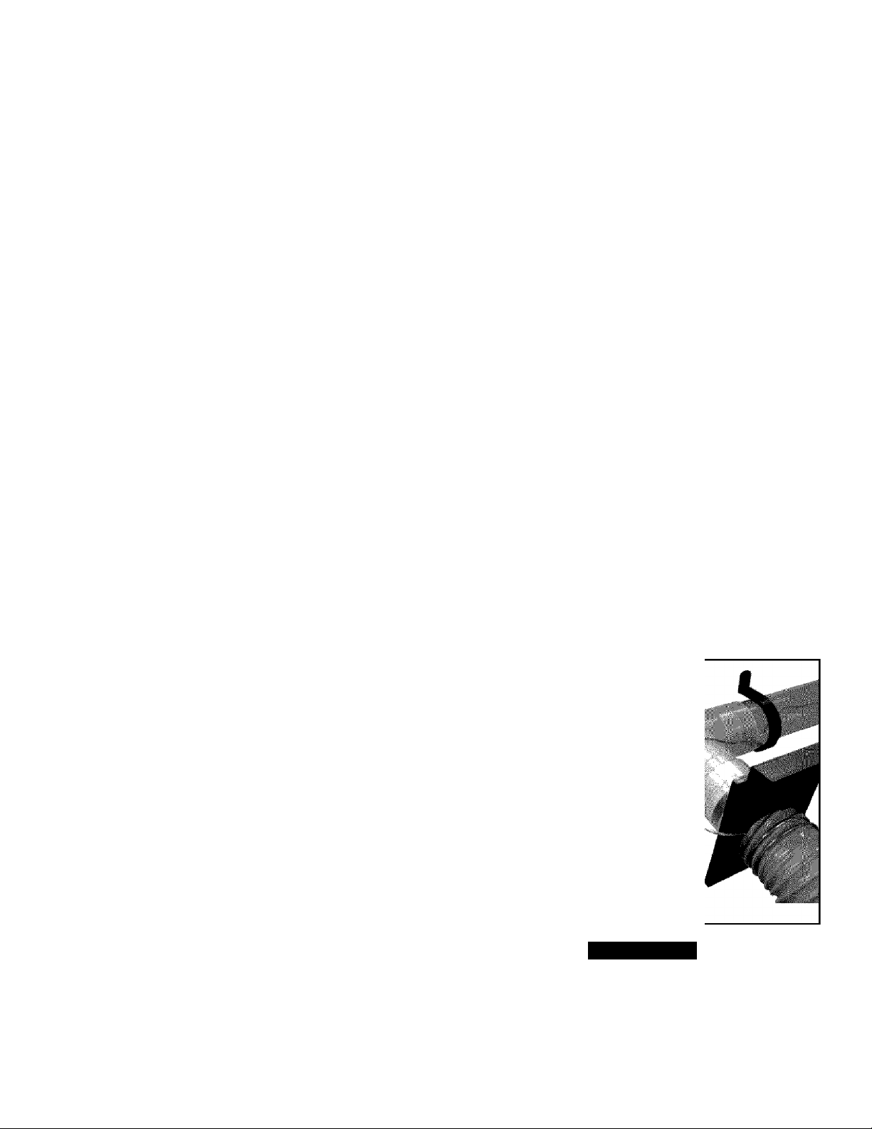
m
Figure 1 - Installing Grounding Kit
OPERATION
DESCRIPTION
The Craftsman Shop Dust Collection System is designed to
remove and collect wood dust and wood chips from wood
working machines. For best performance, use this shop dust
collection system with Craftsman Dust Collector (Model No.
22314).
Page 4

• If this system is used with other dust collectors, the dust
collector must be rated at least 3V2" (of water) static pressure
and 150 cfm at 2V2" diameter. A reducer may be needed.
• This system is not intended to be used with a wet/dry vac.
DANGER: Do not use this dust collection system in a
flammable or explosive atmosphere. Do not use to collect
metal shavings or dust Consult National Fire Protection
Association (NFPA) standards before setting up a dust collec
tion system, especially NFPA 664,
WARNING: Do not connect to dust collector until unit is
completely assembled.
CAUTION: Improper connection of the equipment-grounding
conductor can result in a risk of electrical shock.
Model 351.223130
Open blast gate of machine which will be used. Close all
other blast gates.
Turn dust collector power switch to ON.
Turn woodworking machine power switch to ON.
MAINTENANCE
Refer to Figure 2.
WARNING: Turn dust collector switch off and remove plug
from power source outlet before maintaining your shop dust
collection system.
Clean inside the pipes, fittings and flexible hose using a portable
vacuum cleaner or manually remove large debris as needed.
REPLACEMENT PARTS LIST FOR DUST COLLECTION SYSTEM
KEY
NO. PART NO. DESCRIPTION QTY.
1 23967.00 2V2 X 24” Flexible Hose 1
2 23968.00 Connector 12
3 23969.00 45° Elbow - 2V2" 2
4 23970.00 2V2 X 22" Plastic Straight Pipe 4
5 23971.00 Hanger 8
6 23972,00 2V2" Plastic “T” Fitting 3
7 23973.00 Blast Gate 4
8 23974.00 2V2" Hose Clamp 10
9 23975.00 2V2 X 72” Flexible Hose 4
10 23976.00 Mounting Hardware Kit 1
11 23977.00 Grounding Kit 1
A 23964.00 ID/Warning Label 1
A 23961.01 Operator’s Manual 1
A Not Shown
0
Page 5

SISTEMA DE RECOLECCION
DE POLVO para Talleres
Modelo No.
351.223130
PRECAUCION: Lea у siga todas las Reglas
de Seguridad e Instrucciones de Operación
antes de utilizar este producto por primera vez.
CONTENIDO
Inglés .....................................................................................................2-4
Ilustración y Lista de Partes......................................................................4
Garantía.....................................................................................................5
Reglas de Seguridad.................................................................................5
Desempaque..........................................................................................5-6
Montaje...................................................................................................6-7
Operación..................................................................................................7
Mantenimiento...........................................................................................7
GARANTIA
GARANTIA COMPLETA DE UN ANO PARA
HERRAMIENTA CRAFTSMAN
Si esta herramienta Craftsman fallara por causa de defectos en el
material o en la mano de obra en un lapso de un año a partir de la
fecha de compra, LLAME al 1-800-4-MY-HOME® PARA SOLICITAR
LA REPARACION GRATUITA DEL PRODUCTO.
Si esta herramienta se usa para fines comerciales o de alquiler, esta
garantía es válida únicamente por noventa días a partir de la fecha
de compra.
Esta garantía aplica únicamente si la herramienta se encuentra
en los Estados Unidos.
Esta garantía le otorga derechos legales específicos y también
puede usted tener otros derechos que varíen de estado a estado.
Sears, Roebuck and Co., Dept. 817WA, Hoffman Estates, IL 60179
REGLAS DE SEGURIDAD
PELIGRO: No utilice este sistema de recolección de polvo en
ambientes inflamables o explosivos. No lo utilice para recolectar
polvo o virutas metálicas. Consulte las normativas de la Asociación
Nacional de Protección contra Incendios (National Pire Protection
Assooiation, NFPA) antes de instalar un sistema de recolección
de polvo, especialmente la NFPA 664.
ADVERTENCIA: Por su propia seguridad, lea todas las
instrucciones y precauciones antes de manejar la herramienta.
ADVERTENCIA: Por su propia seguridad, lea todas las
instrucciones y precauciones correspondientes a todo colector
de polvo que se utilice con este sistema.
PRECAUCION: Siempre siga los procedimientos de funcionamiento
correctos, tal como se definen en este manual, aun cuando esté
familiarizado con el uso de ésta o de otras herramientas similares.
Recuerde que descuidarse aunque sólo sea por una fracción de
segundo puede ocasionarle graves lesiones.
EL OPERADOR DEBE ESTAR PREPARADO PARA
ELTRABAJO
• Use ropa apropiada. No use ropa holgada, guantes, corbatas,
anillos, pulseras ni otras joyas que puedan atascarse en las
piezas móviles de la máquina.
• Use una cubierta protectora para el cabello, para sujetar el
cabello largo.
• Use zapatos de seguridad con suela antideslizante.
• Use gafas de seguridad que cumplan con la norma ANSI Z87.1
de los Estados Unidos. Los anteojos comunes tienen lentes que
sólo son resistentes al impacto. NO son anteojos de seguridad.
• Use una máscara facial o una máscara contra el polvo, si al
utilizar la herramienta se produce mucho polvo.
• Esté alerta y piense claramente. Nunca maneje herramientas
mecánicas cuando esté cansado, intoxicado o bajo la influencia
de medicación que produzca somnolencia.
PREPARE EL AREA DE TRABAJO PARA LA TAREA
A REALIZAR
• Mantenga el área de trabajo limpia. Las áreas de trabajo
desordenadas atraen accidentes.
• No use herramientas mecánicas en ambientes peligrosos. No
use herramientas mecánicas en lugares húmedos o mojados.
No exponga las herramientas mecánicas a la lluvia.
• El área de trabajo debe estar iluminada adecuadamente.
• Debe haber disponible una toma de corriente adecuada para
la herramienta. El enchufe de tres puntas debe enchufarse
directamente a un receptáculo para tres puntas puesto a tierra
correctamente.
• Los cordones de extensión deben tener una punta de conexión
a tierra, y los tres hilos del cordón de extensión deben ser del
calibre correcto.
• Mantenga a los visitantes a una distancia prudente del área
de trabajo.
• Mantenga a los niños fuera del lugar de trabajo. Haga que
su taller sea a prueba de niños. Use candados, interruptores
maestros y extraiga las llaves del arrancador para impedir
cualquier uso involuntario de las herramientas mecánicas.
PELIGRO: La operación de toda herramienta mecánica puede
hacer que salgan arrojados objetos extraños hacia los ojos y les
causen graves heridas. Antes de comenzar a utilizar la herramienta
mecánica, póngase siempre gafas de seguridad (mostradas en el
empaque) que cumplan con la norma ANSI Z87.1 de los Estados
Unidos.
DESEMPAQUE
Verifique que no hayan ocurrido daños durante el envío. De ser
así, deberá enviarse de inmediato una reclamación a la compañía
transportista. Verifique que esté completa. Avísele inmediatamente
al distribuidor si faltan partes. Extraiga de la caja de envío todos los
componentes del sistema de recolección de polvo para talleres.
Consulte la Figura 2, página 4.
Ubique y cuente los componentes siguientes:
• Manguera flexible de 2% x 24" (Clave No. 1}
• Conectar (12 de cada uno, Clave No. 2)
• Codos de 45° (2 de cada uno. Clave No. 3)
• Tubo recto de plástico de 214 x 22" (4 de cada uno, Clave No. 4)
• Ganchos de suspensión (8 de cada uno, Clave No. 5)
• Adaptadores en “T” de plástico (3 de cada uno. Clave No. 6}
Page 6

Compuertas de regulación de aire (4 de cada una. Clave No. 7)
Abrazadera de manguera de 2VJ’ (10 de cada una. Clave No. 8)
Manguera flexible de 2'A x 72" (4 de cada una. Clave No. 9}
Equipo de conexión a tierra (no se muestra)
Bolsa de artículos de ferretería (no se muestra)
MONTAJE
HERRAMIENTAS NECESARIAS
Destornillador de punta Phillips
Taladro portátil
Broca de V"
Broca de Vb"
Martillo
AVISO: Para las paredes de mamposterla, utilice dieciséis (16)
anclas para mampostería y una broca para mamposterla de
tamaño adecuado para las brocas (no suministradas).
SELECCIONE EL LUGAR DE INSTALACION
DEL SISTEMA DE RECOLECCION DE POLVO
PARA TALLERES
Consulte la Figura 2, página 4.
El sistema de recolección de polvo para talleres debe situarse lo
más cerca posible de las máquinas de carpintería. El colector de
polvo debe estar a la izquierda o a la derecha de las máquinas y el
sistema de recolección de polvo para talleres debe ramificarse hasta
cada máquina. Se recomienda situar más cerca del colector de polvo
aquellas máquinas que produzcan mayor cantidad de polvo.
ADVERTENCIA: Existe el riesgo de que en el sistema de
recolección de polvo se acumule electricidad estática y se
produzca una explosión o un incendio. Para evitar la acumulación
de electricidad estática, instale el equipo de conexión a tierra.
• Se incluye un equipo de conexión a tierra que debe instalarse
en el sistema de recolección de polvo para talleres con el objeto
de protegerlo de descargas electrostáticas. Resulta más fácil
instalar el equipo de conexión a tierra a medida que se
montan las secciones individuales de cada máquina.
TIENDA EL SISTEMA EN EL LUGAR SELECCIONADO
Monte temporalmente las piezas como se describe a continuación
de modo de determinar la posición de los ganchos de suspensión
y la ubicación de sus correspondientes anclas de pared.
• Use un conectar para unir el tubo recta de plástico de 2'A x 22" y
el codo de 45 grados.
• Use un conectar para unir el adaptador en “T" y el tubo recto
de plástico de 2'A x 22".
• Repita los pasos 2 y 3 para conectar a cada máquina adicional.
• Con la última máquina, use un conectar para unir el codo de 45°
y el tubo recto de plástico de 2'A x 22".
• Válgase de chapas de 2 x 4 para fijar a la pared el conjunto
temporal de tubos de plástico y adaptadores en “T". El orificio
de entrada debe estar a menos de 24" del colector de polvo.
• Sitúe los ganchos de suspensión a aproximadamente 6" de cada
extremo del tubo recto de plástico de 2'A x 22", y marque la
ubicación de los agujeros para cada gancho.
INSTALE ANCLAS PARA PARED
Las anclas para pared deben instalarse en el lugar seleccionado para
el colector de polvo. Para instalar las anclas para pared en la pared:
• En cada marca para ganchos de suspensión, haga un agujero
de
Va"
de diámetro y VA" de profundidad.
• Con un martillo, clave las anclas en cada agujero hasta dejarlas
al ras con la pared.
MONTAJE PERMANENTE
Consulte las Figuras 1 y 2, páginas 7 y 4.
Monte en las anclas de pared la primera sección de tubo recto de
plástico y adaptador en “T” mediante los ganchos de suspensión
y los tornillos formadores de rosca.
Haga un agujero de 'tí' en la primera sección de tubo recta de
plástico en el lugar donde se une con el adaptador en “T".
Corte un tramo de cable de conexión a tierra de longitud
equivalente a 4' de tubo de plástico más la longitud de la
manguera que conecta el tubo y el colector de polvo.
Pase el cable de conexión a tierra por el interior del tubo recto
de plástico y la manguera hasta llegar al colector de polvo.
Haga agujeros de
polvo, y pase el cable de conexión a tierra por el agujero.
Conecte la manguera entre el tubo y el colector de polvo.
Conecte el extremo del cable de conexión a tierra al tornillo
metálico del colector de polvo.
Pase el otro extremo del cable de conexión a tierra a través
del agujero de
Monte en las anclas de pared las secciones adicionales de tubo
recto plástico y adaptadores en “T” mediante los ganchos de
suspensión y los tornillos formadores de rosca.
Haga un agujero de 'tí' en ambos extremos de cada sección de
tubo recto de plástico en el lugar donde se une al adaptador
en “T”.
Pase 4' de cable de conexión a tierra por el interior de cada tubo
recto de plástico.
Pase cada extremo del cable de conexión a tierra a través de
los agujeros de
Una vez instaladas las mangueras flexibles, una los cables de
conexión a tierra con las tuercas para cable (vea la Figura 1).
Use un conectar para unir las compuertas de regulación de
aíre a cada adaptador en “T".
Verifique el apriete de todos los tornillos formadores de rosca
que sujetan a las anclas.
Va"
en la manguera, del lado del colector de
Vb".
Va".
CONECTE MANGUERAS FLEXIBLES A LAS MAQUINAS
Consulte las Figuras 1 y 2, páginas 7 y 4.
Las mangueras se conectan a la compuerta de regulación de aire
y las máquinas de carpintería mediante abrazaderas de manguera.
Para conectar mangueras:
Deslice la abrazadera sobre un extremo de la manguera flexible
de 2'A X 72". Afloje el tornillo de la abrazadera, sí es necesario,
para deslizar la abrazadera sobre la manguera.
Ponga los cables de la abrazadera en las ranuras de la
manguera.
Pase 8' de cable de conexión a tierra por el interior de la
manguera flexible.
Haga agujeros de 'tí' en cada extremo de la manguera y pase el
cable por los agujeros.
Deslíce por la compuerta de regulación de aire la manguera
junto con la abrazadera y el cable de conexión a tierra.
Apriete el tornillo de la abrazadera para fijar la manguera a la
compuerta de regulación de aire.
Deslíce la otra abrazadera por el extremo opuesto de la
manguera.
Conecte la manguera al orificio de salida de polvo de la máquina.
Page 7

Verifique el apriete de todas las abrazaderas de manguera.
Conecte el extremo del cable de conexión a tierra de la máquina
a la parte metálica de la máquina. Use un tornillo o un perno
con arandela de seguridad para garantizar una buena conexión
a tierra.
Tire del otro extremo del cable y páselo alrededor de la
compuerta de regulación de aire para conectar a los cables
de los tubos (vea la Figura 1).
Junte los tres hilos de cobre de cada adaptador en “T” y retuerza
para unirlos. Enrosque la tuerca del cable sobre los tres hilos.
Cerciórese de que hayan quedado firmes la tuercas del cable.
Una vez montado el sistema, cierre todos los agujeros de
Ve" con masilla de calafateo para evitar fugas de aire.
Figura 1 - Instalación del Equipo de Conexión a Tierra
• Si usa este sistema con otros colectores de polvo, el colector de
polvo debe estar especificado, al menos, para una presión estáti
ca de 3’/2" (de agua) y 150 piesVmin a de diámetro.
Posiblemente sea necesario usar un reductor.
• Este sistema no ha sido diseñado para usarse con aspiradoras
de materiales sólidos o líquidos.
PELIGRO: No utilice este sistema de recolección de polvo en
ambientes inflamables o explosivos. No lo utilice para recolectar polvo
ni virutas metálicas. Antes de instalar un sistema de recolección de
polvo, consulte la normativa de la Asociación Nacional de Protección
contra Incendios (National Fire Protection Association, NFPA),
especialmente la NFPA 664.
ADVERTENCIA: No conecte el colector de polvo hasta haber
montado completamente la unidad.
PRECAUCION: Si no se conecta correctamente el conductor a
tierra del equipo, se corre el riesgo de un electrochoque.
• Abra la compuerta de regulación de aire de la máquina que va
a usar. Cierre el resto de las compuertas de regulación de aire.
• ENCIENDA el colector de polvo.
• ENCIENDA la máquina de carpintería.
MANTENIMIENTO
Consulte la Figura 2, página 4.
ADVERTENCIA: Apague el interruptor y extraiga el enchufe
del tomacorrienfe de la fuente de alimentación antes de darle
mantenimiento al sistema de recolección de polvo para talleres.
Limpie el interior de los tubos, los adaptadores y la manguera
flexible mediante una aspiradora portátil, o elimine manualmente
los residuos de mayor tamaño, según sea necesario.
OPERACION
DESCRIPCION
El Sistema de Recolección de Polvo para Talleres Craftsman ha sido
diseñado para extraer y recolectar el polvo y las astillas producidas
por las máquinas de carpintería. Para un mejor desempeño, use
este sistema de recolección de polvo para talleres con un Colector de
Polvo Craftsman (Modelo No. 22314).
Page 8

Get it fixed, at your home or ours!
Your Home
For repair-in your home-of all major brand appliances,
lawn and garden equipment, or heating and cooling systems,
no matter who made It, no matter who sold It!
For the replacement parts, accessories and
owner’s manuals that you need to do-it-yourself.
For Sears professional installation of home appliances
and items like garage door openers and water heaters.
1-800-4-MY-HOME® (1-800-469-4663)
Call anytime, day or night (U.S.A. and Canada)
www.sears.com www.sears.ca
Our Home
For repair of carry-in items like vacuums, lawn equipment,
and electronics, call or go on-line for the location of your nearest
Sears Parts & Repair Center.
1-800-488-1222
Call anytime, day or night (U.S.A. only)
www.sears.com
To purchase a protection agreement (U.S.A.)
or maintenance agreement (Canada) on a product serviced by Sears:
1-800-827-6655 (U S A ) 1-800-361-6665 (Canada)
Para pedir servicio de reparación
a domicilio, y para ordenar piezas:
1-888-SU-HOGAR®“
(1-888-784-6427)
Au Canada pour service en français:
1-800-LE-FOYER“^
(1-800-533-6937)
www.sears.ca
® Registered Trademark / ™ Trademark / ®’''’ Service Mark of Sears, Roebuck and Co.
® Marca Registrada / ™ Marca de Fábrica / Marca de Servicio de Sears, Roebuck and Co.
Marque de commerce / Marque déposée de Sears. Roebuck and Co.
©Sears, Roebuck and Co.
 Loading...