

Craftsman 351218330 Owner’s Manual

Operator's Manual
CRAFTSMAN
10"
CONTRACTOR TABLE SAW
Model No.
351.218330
CAUTION:
Read and follow all Safety
Rules and Operating
Instructions before First
Use of this Product. Keep
this Manual with Tool.
Sears, Roebuck and Co., Hoffman Estates, IL 60179 U.S.A.
www, sears.com/craftsman
31105,00 Draft (07/01/09)
Warranty ......................................... 2
Safety Rules .................................... 2-5
Unpacking ....................................... 5
Assembly ...................................... 6-8
Installation ...................................... 8-9
Operation ..................................... 9-13
Maintenance .................................... 13
Repair Protection Agreement ....................... 14
Troubleshooting ............................... 16-17
Parts Illustration and List ........................ 18-29
Espafiol ...................................... 30-47
ONE-YEAR FULL WARRANTY ON CRAFTSMAN
TOOL
if this Craftsman toolfails due to adefect inmaterial or
workmanshipwithinoneyear from thedate ofpumhase,call
1-800-4-MY-HOME®TO ARRANGE FOR FREE REPAIR(or
replacementif repairprovesimpossible).
Thiswarrantydoes notcoverthe blade, whichisan
expendable part.
(fthistooliseverusedfor commercialorrentalpurposes,this
warrantywillapplyfor only90 daysfrom the dateofpurchase.
Thiswarrantygivesyou specific legalrightsandyoumay also
have other rightswhichvaryfrom state to state.
Sears, Roebuck and Co., Hoffman Estates,IL 60179
WARNING: For your own safety, read allof the instructions
and precautions before operating tool.
PROPOSITION 65 WARNING: Some dust created by
power sanding, sawing, grinding, drilling and other construc-
tion activities contains chemicals known to the state of
California to cause cancer, birth defects or other reproductive
harm.
Some examples of these chemicals are:
• Lead from lead-based paints.
• Crystalline silica from bricks and cement and other
masonry products.
• Arsenic and chromium from chemically-treated lumber.
Your risk from these exposures vary, depending on how often
you do this type of work. To reduce your exposure to these
chemicals: work in a well ventilated area and work with
approved safety equipment. Always wear OSHNNIOSH
approved, properly fitting face mask or respirator when using
such tools.
CAUTION: Always follow proper operating procedures as
defined in this manual -- even if you are familiar with use of
this or similar tools. Remember that being careless for even a
fraction of a second can result in severe personal injury'.
BE PREPARED FOR JOB
• Wear proper apparel. Do not wear loose clothing, gloves,
neckties,rings, braceletsor otherjewelrywhichmay get
caughtinmovingpartsof machine.
© Sears, Roebuck and Co.
• Wear protective hair covering to contain long hair.
° Wear safety shoes with non-slip soles.
° Wear safety glasses complying with United States ANSI
Z87.1. Everyday glasses have only impact resistant lens-
es. They are NOT safety glasses.
° Wear face mask or dust mask if operation is dusty.
• Be alert and think clearly. Never operate power tools when
tired, intoxicated or when taking medications that cause
drowsiness.
PREPARE WORK AREA FOR JOB
• Keep work area clean. Cluttered work areas invite acci-
dents.
• Do not use power toolsindangerous environments. Do not
use powertoolsindamp or wet locations.Do not expose
power toolsto rain.
• Work area should beproperlylighted.
° Keepvisitorsat a safedistancefrom workarea.
• Keep childrenoutof workplace.Make workshopchildproof.
Use padlocks,master switchesor removeswitchkeysto
prevent anyunintentionaluseof powertools.
• Keep power cordsfromcomingin contactwithsharp
objects,oil,greaseandhot surfaces.
TOOL SHOULD BE MAINTAINED
• Always unplugtoolpriorto inspection.
• Consult manual for specificmaintainingand adjusting pro-
cedures.
• Keep tool lubricated and clean for safest operation.
° Remove adjusting tools. Form habit of checking to see that
adjusting tools are removed before switching machine on.
• Keep all parts in working order. Check to determine that
the guard or other parts will operate properly and perform
their intended function.
° Check for damaged parts. Check for alignment of moving
parts, binding, breakage, mounting and any other condi-
tion that may affect a tool's operation.
• A guard or other part that is damaged should be properly
repaired or replaced. Do not perform makeshift repairs.
(Use parts list provided to order replacement parts.)
• Maintain proper adjustment of rip fence and blade guard.
• Never adjust saw while running. Disconnect power to avoid
accidental start-up.
° Have damaged or worn power cords replaced immediately.
° Keep blade sharp for efficient and safest operation.
KNOW HOW TO USE TOOL
• Use right tool for job. Do not force tool or attachment to do
a job for which it was not designed.
• Disconnect tool when changing blade.
• Avoid accidental start-up. Make sure that the tool is in the
"off" position before plugging in, turning on safety discon-
nect or activating breakers.
° Do not force tool. It will work most efficiently at the rate for
which it was designed.
• Keep hands away from blade and moving parts and cutting
surfaces.
° Never leave tool running unattended. Turn the power off
and do not leave tool until it comes to a complete stop.
• Do not overreach. Keep proper footing and balance.
° Never stand on tool. Serious injury could occur if tool is
tipped or if blade is unintentionally contacted.
2
• Know your tool. Learn the tool's operation, application and
specific limitations.
° Handle workpiece correctly. Press firmly against table.
Protect hands from possible injury.
• Turn machine off if it jams. Blade jams when it digs too
deeply into workpiece. (Motor force keeps it stuck in the
work.)
• Feed work into the blade only as recommended in
"Operation"
WARNING: For your own safety, do not operate your saw until it
is completely assembled and installed according to instructions.
STABILITY OF SAW
Ifthere is anytendencyfor the saw to tip overor moveduring
certaincuttingoperations,such as cuttingextremelyheavy
panels or long heavy boards,the saw shouldbe bolteddown.
Ifyouattach anykind ofextensionsover24" wide toeither
end ofthe saw, make sure you either boltthe saw to thefloor,
as appropriate, orsupport theouterend ofthe extension from
the benchor floor, as appropriate.
LOCATION
The saw should be positioned so neither the operator nor a
casual observer is forced to stand in line with the saw blade.
KICKBACKS
A kickback occurs during a rip-type operation when a part or
all of workpiece is thrown back violently toward operator.
Keep your face and body to one side of the saw blade, out of
line with a possible kickback.
Kickbacks and possible injury from them can usually be avoid-
ed by:
• Maintaining rip fence parallel to saw blade.
• Keeping saw blade sharp. Replace or sharpen anti-kick-
back pawls when points become dull.
• Keeping saw blade guard, spreader, and anti-kickback
pawls in place and operating properly. The spreader must
be in alignment with the saw blade and the pawls must
stop a kickback once it has started. Check their action
before ripping.
° Not ripping work that is twisted or warped or does not
have a straight edge to guide along the rip fence.
• Not releasing work until you have pushed it all the way
past the saw blade.
• Using a push stick for ripping widths less than 6 inches.
° Not confining the cutoff piece when ripping or crosscutting.
PROTECTION: EYES, HANDS, FACE, BODY, EARS
• If any part of your saw is missing, malfunctioning, or has
been damaged or broken (such as the motor switch, elec-
tronic controls, other operating control, a safety device or
power cord), cease operating immediately until the partic-
ular part is properly repaired or replaced.
• Wear safety goggles that comply with United States ANSI
Z87.1 and a face shield or dust mask if operation is dusty.
Wear ear plugs or muffs during extended periods of oper-
ation.
Small loose pieces of wood or other objects that contact
the rear of the revolving blade can be thrown back at the
operator at excessive speed. This can usually be avoided
by keeping the guard and spreader in place for all thru-
sawing operations (sawing entirely thru work) and by
removing all loose pieces from the table with a long stick
of wood immediately after they are cut off.
• Use extra caution when the guard assembly is removed for
resawing, dadoing, or rabbeting--replace guard as soon
as that operation is completed.
• Never turn the saw ON before clearing the table of all
tools, wood scraps, etc., except the workpiece and related
feed or support devices for the operation planned.
• Never place your face or body in line with the cutting tool.
• Never place your fingers or hands in path of saw blade or
other cutting tool.
• For rip or rip-type cuts, the following end of a workpiece to
which a push stick or push board is applied must be
square (perpendicular to the fence) in order that feed
pressure applied to the workpiece by the push stick or
block does not cause the workpiece to come away from
the fence, and possibly cause a kickback.
• During rip and rip-type cuts, workpiece must be herd down
on table and against fence with a push stick, push block,
or featherboards, as applicable (see Figures l a and lb,
page 4).
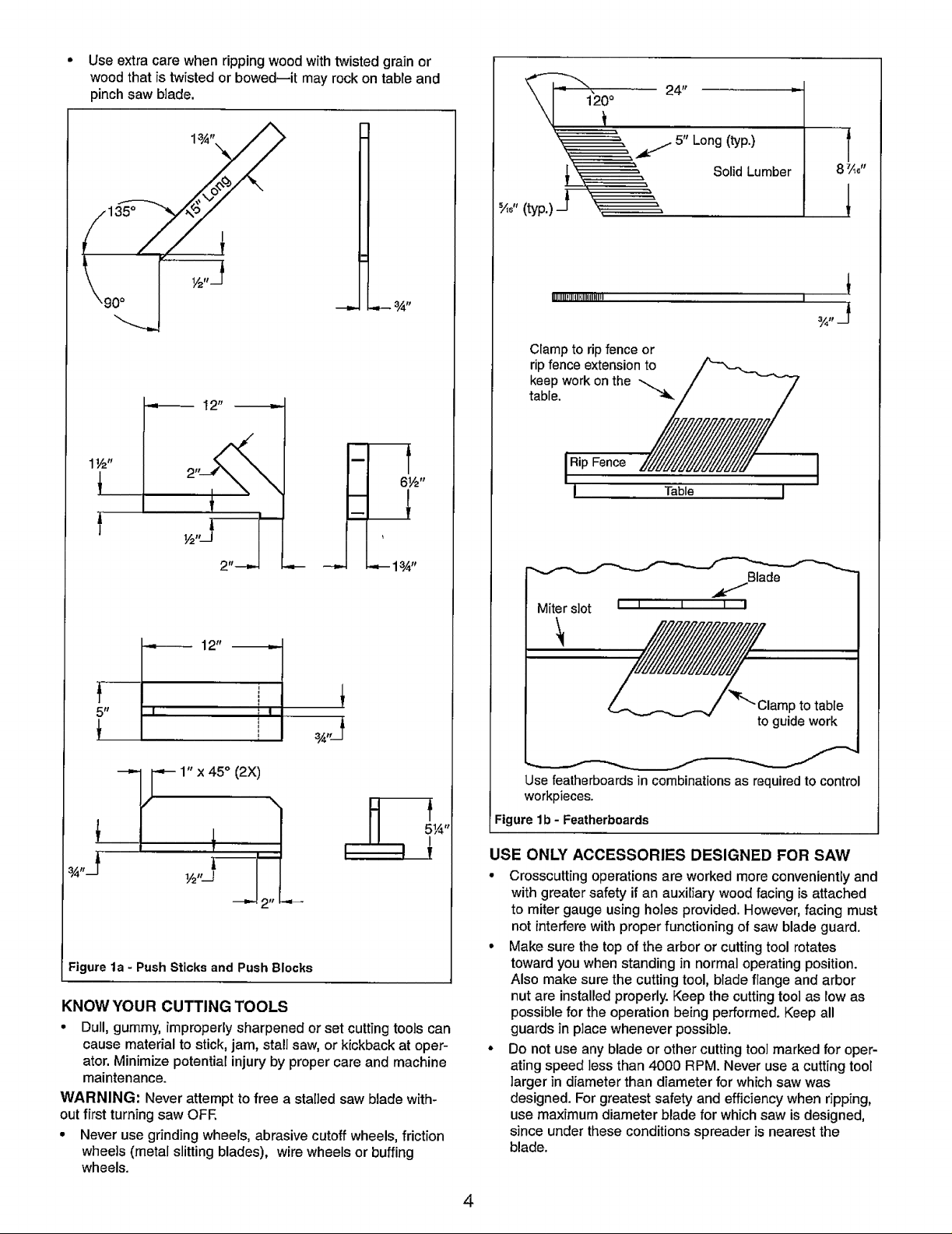
The push stick and push block examples shown below are use-
ful for keeping hands and fingers away from saw blade during
ripping, rabbeting and dadoing. Apply downward pressure and
push workpiece through the cut and past the blades. Several
other configurations may be suitable for safe operation.
Featherboards are used to keep the work in contact with the rip
fence or table during the cutting operation. Use of featherboards
can help to prevent kickbacks and binding. Featherboards
should be used for all "non thru-sawing" operations.
• Never reach in back of the cutting tool with either hand to
hold down or support the workpiece, remove wood scraps,
or for any other reason. Avoid awkward operations and
hand positions where a sudden slip could cause fingers or
hand to move into a saw blade or other cutting tool.
• Do not perform layout, assembly, or setup work on the
table while the cutting tool is rotating.
• Do not perform any operation freehand--always use either
rip fence or miter gauge to position and guide the work.
• Never use the rip fence when cross-cutting or the miter gauge
when ripping. Do not use rip fence as a length stop. Never
hold onto ortouch free-end of workpiece or a free-piece that
is cut off, while power is ON and/or saw blade is rotating.
• Shut the saw OFF and disconnect power source when
removing the table insert, changing the cutting too],
removing or replacing the blade guard, or making adjust-
ments.
Provide adequate support to the rear and sides of the saw
table for wide or long workpieces.
ib
Plastic and composition materials (like hardboard) may be
cut on your saw. However, since these are usually quite
hard and slippery, the anti-kickback pawls may not stop a
kickback. Therefore, be especially attentive to following
proper setup and cutting procedures for ripping. Do not
stand, or permit anyone else to stand, in line with a poten-
tial kickback.
• If you stall or jam the saw blade in the workpiece, turn saw
OFF and remove the workpiece from the saw blade.
Check to see if the saw blade is parallel to the miter
gauge grooves and if the spreader is in proper alignment
with the saw blade. If ripping at the time, check to see if
the rip fence is parallel with the saw blade. Readjust as
required.
• Do not remove small pieces of cutoff material that may
become trapped inside the blade guard while the saw is
running. This could endanger your hands or cause kick-
back. Turn saw OFF and wait until blade stops.
3
Use extra care when ripping wood with twisted grain or
wood that is twisted or bowed--it may rock on table and
pinch saw blade.
4 It
5" Long (typ.)
Solid Lumber
1½"
+
12"
- t
6½"
,-- 13A,,
%+"(typ.) J "_
IIIIIll}[IlUHIIilIlUlI" I
Clamp to rip fence or
rip fence extension to
keep work on the
table.
I Rip Fence
I Table
Miter slot
•_,;,,,, ,,
+
¾,,J
Blade
I I .........,I I I
i ' +
5 +1
!I_12"
+ i
2
Figure la - Push Sticks and Push Blocks
KNOW YOUR CUTTING TOOLS
• Dull, gummy, improperly sharpened or set cutting tools can
cause material to stick, jam, stall saw, or kickback at oper-
ator. Minimize potential injury by proper care and machine
maintenance.
WARNING: Never attempt to free a stalled saw blade with-
out first turning saw OFE
• Never use grinding wheels, abrasive cutoff wheels, friction
wheels (metal slitting blades), wire wheels or buffing
wheels.
p to table
to guide work
Use featherboards in combinations as required to control
workpieces.
Figure lb - Featherboards
USE ONLY ACCESSORIES DESIGNED FOR SAW
• Crosscutting operations are worked more conveniently and
with greater safety if an auxiliary wood facing is attached
to miter gauge using holes provided. However, facing must
not interfere with proper functioning of saw blade guard.
° Make sure the top of the arbor or cutting tool rotates
toward you when standing in normal operating position.
Also make sure the cutting tool, blade flange and arbor
nut are installed properly. Keep the cutting tool as low as
possible for the operation being performed. Keep all
guards in place whenever possible.
• Do not use any blade or other cutting tool marked for oper-
ating speed less than 4000 RPM. Never use a cutting tool
larger in diameter than diameter for which saw was
designed. For greatest safety and efficiency when ripping,
use maximum diameter blade for which saw is designed,
since under these conditions spreader is nearest the
blade.
4
• Adjust table inserts flush with table top. Never operate saw
unless proper insert is installed.
• Never feed material into the cutting tool from the rear of
the saw. An accident and serious injury could result.
THINK SAFETY
Safety is a combination of operator common sense and alert-
ness at all times when the saw is being used.
Never use another person as a substitute for a table exten-
sion, or as additional support for a workpiece that is longer or
wider than basic saw table, or to assist in feeding, supporting
or pulling the workpiece.
Do not pull the workpiece through the saw blade--position
your body at the infeed side of the guard; start and complete
the cut from that same side. This will require added table sup-
port for long or wide workpieces that extend beyond the
length or width of the saw table.
CAUTION: Follow safety instructions that appear on the front
of your saw.
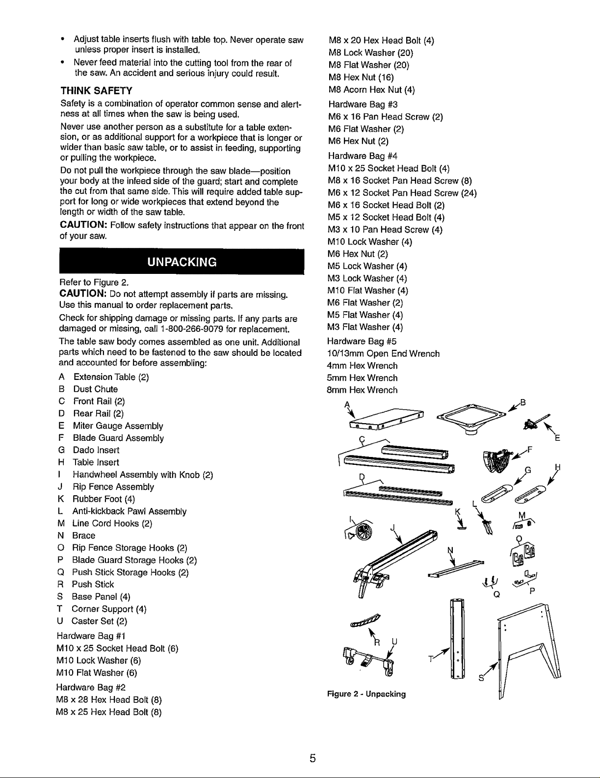
Refer to Figure 2.
CAUTION: Do not attempt assembly if parts are missing.
Use this manual to order replacement parts.
Check for shipping damage or missing parts. If any parts are
damaged or missing, calt 1-800-266-9079 for replacement.
The table saw body comes assembled as one unit. Additional
parts which need to be fastened to the saw should be located
and accounted for before assembling:
A Extension Tab]e (2)
B Dust Chute
C Front Rail (2)
D Rear Rail (2)
E Miter Gauge Assembly
F Blade Guard Assembly
G Dado Insert
H Tab]e Insert
I Handwheel Assembly with Knob (2)
J Rip Fence Assembly
K Rubber Foot (4)
L Antkkickback Pawi Assembly
M Line Cord Hooks (2)
N Brace
O Rip Fence Storage Hooks (2)
P Blade Guard Storage Hooks (2)
Q Push Stick Storage Hooks (2)
R Push Stick
S Base Panel (4)
T Corner Support (4)
U Caster Set (2)
Hardware Bag #1
M!0 x 25 Socket Head Bolt (6)
M10 Lock Washer (6)
M10 Flat Washer (6)
Hardware Bag #2
M8 x 28 Hex Head Bolt (8)
M8 x 25 Hex Head Bolt (8)
M8 x 20 Hex Head Bolt (4)
M8 Lock Washer (20)
M8 Flat Washer (20)
M8 Hex Nut (16)
M8 Acorn Hex Nut (4)
Hardware Bag #3
M6 x 16 Pan Head Screw (2)
M6 Flat Washer (2)
M6 Hex Nut (2)
Hardware Bag #4
MI0 x 25 Socket Head Bolt (4)
M8 x 16 Socket Pan Head Screw (8)
M6 x 12 Socket Pan Head Screw (24)
M6 x 16 Socket Head Bolt (2)
M5 x 12 Socket Head Bolt (4)
M3 x 10 Pan Head Screw (4)
M10 Lock Washer (4)
M6 Hex Nut (2)
M5 Lock Washer (4)
M3 Lock Washer (4)
M10 Flat Washer (4)
M6 Flat Washer (2)
M5 Flat Washer (4)
M3 Flat Washer (4)
Hardware Bag #5
10/I3mm Open End Wrench
4mm Hex Wrench
5mm Hex Wrench
8mm Hex Wrench
S
a
L._
Figure 2 - Unpacking
E
_F
L
Q P
5
IMPORTANT: Table is coated with a protectant. To ensure
proper fit and operation, remove coating. Coating is easily
removed with mild solvents, such as mineral spirits, and a soft
cloth. Avoid getting solution on paint or any of the rubber or
plastic parts. Solvents may deteriorate these finishes. Use
soap and water on paint, plastic or rubber components. After
cleaning, cover all exposed surfaces with a light coating of oil.
Paste wax is recommended for table top.
WARNING: Never use highly volatile solvents. Non flamma-
ble solvents are recommended to avoid possible fire hazard.
Refer to Figures 3, 4, 5, 7, 8, 9 and 10.
CAUTION: Do not attempt assembly if parts are missing.
Use this manual to order replacement parts.
Be certain all parts are clean and free of shipping preserva-
tive. Also, completely remove all parts of packing. Saw cabinet
should be directly on the floor.
SAW INSTALLATION
Positioning the saw on a level surface (shimming may be
required) will improve stability and accuracy and prevent
warpage and failure of cast components and welds.
WARNING; Make certain that the saw is disconnected from
the power source.
ASSEMBLE THE MOBILE BASE
Refer to Figure 12, page 24.
NOTE: Finger tighten bolts and nuts until assembly of mobile
base is complete. Then tighten all fasteners securely.
• Use two M8 x 16 socket pan head bolts (Key No. 1) to
attach a corner support bracket (Key No. 3) to each fixed
support (Key Nos. 9 and 29) at the ends of one of the
caster sets.
• Repeat for the other caster set.
° Attach the front panel (Key No. 8 - stamped 'A') between
the two corner supports attached to one of the caster sets
using six M6 x I2 socket pan head bolts (Key No. 2).
Note: Place the panel edges INSIDE the corner support
surfaces.
• Attach the rear panel (Key No. 8) between the two corner
supports attached to the remaining caster set.
= Attach the left side panel (Key No. 25 - stamped 'B') to the
assemblies made in the previous two steps.
• Attach the right side panel (Key No. 33 - stamped 'C') to
the assembly made in the previous step.
ASSEMBLE BASE TO CABINET
Refer to Figures i0 and 12, pages 20 and 24.
NOTE: Saw cabinet and base are very heavy. Two people are
required to assemble this saw.
° Place a large sheet of cardboard or carpet on the floor to
protect the table top.
• Carefully place the saw cabinet upside down on the floor.
° Remove the six bolts and the back panel (Fig. 10, Key
Nos. 2 and 24). This will allow you to adjust the cabinet
holes to align with the base holes.
° Place the dust chute (Fig. 12, Key No. 30) on the cabinet
with the chute facing upwards.
° Place the mobile base assembly onto the cabinet and dust
chute and secure in position with four socket head bolts,
lock washers and flat washers (Fig. 12, Key Nos. 10, 11
and 12).
NOTE: The foot pedals of the caster sets face towards front
and rear of cabinet, the push stick is attached to the left side
of the base and rip fence hooks are on the right side of the
base.
• Press the four rubber feet (Fig. 12, Key No. 4) to the base
legs.
° Turn the saw upright, reattach the back panel of the
cabinet.
HANDWHEEL ASSEMBLY
Refer to Figure 13, page 26.
WARNING: Make certain that the saw is disconnected from
the power source.
• Place one of the handwheels (Key No. 30) onto the blade
raise/lower shaft (Key No. 56) located on the front of the
cabinet. Align the groove in the back of the handwheel
with the pin.
° Thread the locking knob (Key No. 27) onto the threaded
end of the shaft.
° Repeat the steps above to assemble the remaining hand-
wheel and locking knob onto the bevel shaft located on
the right side of the cabinet.
ATTACH LINE CORD HOOKS
Refer to Figure 10, page 20.
° Tilt the tableto 45°.
° Installthe linecordhooks(KeyNo.9)usingsockethead
bolts, washersand nuts(KeyNos.10, 12 and 13) to the
leftside of thesaw cabinet.
ASSEMBLE BLADE GUARD STORAGE BRACKETS
Referto Figure 12, page 24.
Installthe blade guardstorage brackets(KeyNos. 18 and 19)
to the leftside pane[ (KeyNo.25) of the base usingfour
screws, lock washers and fiat washers(Key Nos.15, 16
and 17).
ASSEMBLE PUSH STICK STORAGE BRACKETS
Refer to Figure 12, page 24.
Installthepush stickstorage brackets (KeyNo.23) tothe left
side panel(Key No.25) ofthebase usingfour screws, lock
washersandflat washers(KeyNos.20, 2t and 22).
ASSEMBLE RIP FENCE STORAGE BRACKETS
Refer to Figure 12, page 24.
Install the rip fence storage brackets (Key No. 34) to the right
side panel (Key No. 33) of the base using two screws, flat
washers and hex nuts (Key Nos. 14, 31 and 32).
ATTACH EXTENSION TABLES
Refer to Figure 11, page 22.
° Assemble extension table (Key No. 35) to the table using
hex head bolts, lock washers and fiat washers (Key Nos.
36, 37 and 38).
° Hand tighten only. Do not tighten completely until tables
are level.
° Repeat above procedure for the other extension table.
6
• Use a straight edge to check level and flatness between
main and extension tables.
• After tables are adjusted level and flat, secure the exten-
sion tables by tightening the hex nuts completely.
CHECK TABLE ALIGNMENT
Refer to Figures 3 and 13, pages 7 and 26.
• Saws are shipped from the factory with the table adjusted
so the miter gauge slots are parallel to the saw blade.
However, in order to obtain the best results from the saw, it
is suggested this adjustment be checked before operating.
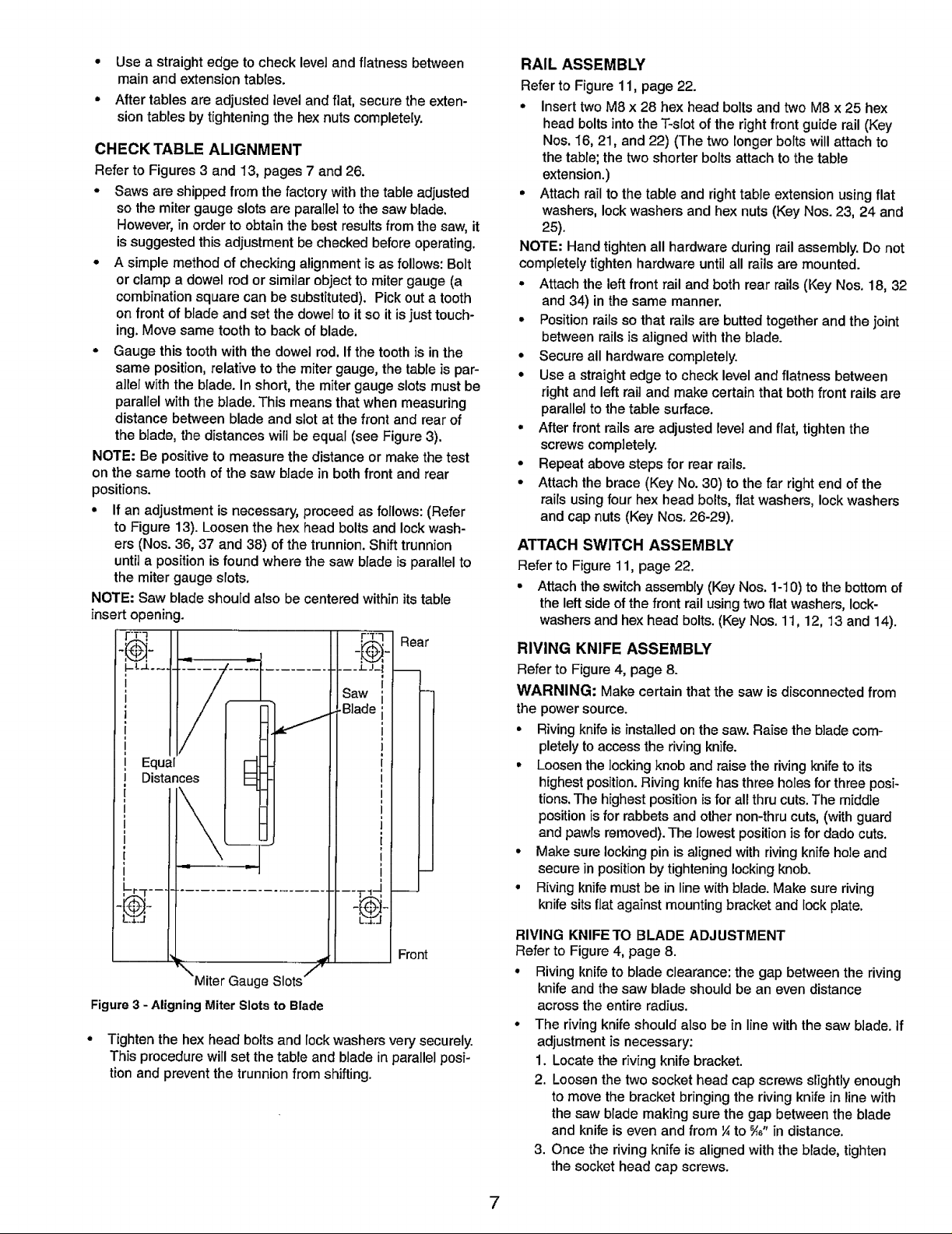
° A simple method of checking alignment is as follows: Bolt
or clamp a dowel rod or similar object to miter gauge (a
combination square can be substituted). Pick out a tooth
on front of blade and set the dowel to it so it is just touch-
ing. Move same tooth to back of blade.
• Gauge this tooth with the dowel rod. If the tooth is in the
same position, relative to the miter gauge, the table is par-
allel with the blade. In short, the miter gauge slots must be
parallel with the blade. This means that when measuring
distance between blade and slot at the front and rear of
the blade, the distances will be equal (see Figure 3).
NOTE: Be positive to measure the distance or make the test
on the same tooth of the saw blade in both front and rear
positions.
• If an adjustment is necessary, proceed as follows: (Refer
to Figure 13). Loosen the hex head bolts and lock wash-
ers (Nos. 36, 37 and 38) of the trunnion. Shift trunnion
until a position is found where the saw blade is parallel to
the miter gauge slots.
NOTE: Saw blade should also be centered within its table
insert opening.
__'1",j_,
Rear
t
I
1
I
i
I
i
I
i
I
i
1
1
I
i
I
i
, r_Y
_aw :
_Blade :
RAIL ASSEMBLY
Refer to Figure 11, page 22.
° Insert two M8 x 28 hex head bolts and two M8 x 25 hex
head bolts into the T-slot of the right front guide rail (Key
Nos. 16, 21, and 22) (The two longer bolts will attach to
the table; the two shorter bolts attach to the table
extension.)
• Attach rail to the table and right table extension using flat
washers, lock washers and hex nuts (Key Nos. 23, 24 and
25).
NOTE: Hand tighten all hardware during rail assembly. Do not
completely tighten hardware until all rails are mounted.
• Attach the left front rail and both rear rails (Key Nos. 18, 32
and 34) in the same manner.
• Position rails so that rails are butted together and the joint
between rails is aligned with the blade.
• Secure all hardware completely.
• Use a straight edge to check level and flatness between
right and left rail and make certain that both front rails are
parallel to the table surface.
• After front rails are adjusted level and flat, tighten the
screws completely.
• Repeat above steps for rear rails.
• Attach the brace (Key No. 30) to the far right end of the
rails using four hex head bolts, flat washers, lock washers
and cap nuts (Key Nos. 26-29).
ATTACH SWITCH ASSEMBLY
Refer to Figure 11, page 22.
• Attach the switch assembly (Key Nos. 1-10) to the bottom of
the left side of the front rail using two flat washers, lock-
washers and hex head bolts. (Key Nos. 11, 12, 13 and 14).
RIVING KNIFE ASSEMBLY
Refer to Figure 4, page 8.
WARNING: Make certain that the saw is disconnected from
the power source.
• Riving knife is installed on the saw. Raise the blade com-
pletely to access the riving knife.
• Loosen the locking knob and raise the riving knife to its
highest position. Riving knife has three holes for three posi-
tions. The highest position is for all thru cuts. The middle
position is for rabbets and other non-thru cuts, (with guard
and pawls removed). The lowest position is for dado cuts.
• Make sure locking pin is aligned with riving knife hole and
secure in position by tightening locking knob.
• Riving knife must be in line with blade. Make sure riving
knife sits flat against mounting bracket and lock plate.
Front
"'Miter Gauge Slots ''f
Figure 3 - Aligning Miter Slots to Blade
° Tighten the hex head bolts and lock washers very securely.
This procedure will set the table and blade in parallel posi-
tion and prevent the trunnion from shifting.
RIVING KNIFETO BLADE ADJUSTMENT
Refer to Figure 4, page 8.
• Riving knifetoblade cJearance:thegap betweenthe riving
knife and thesaw blade should be an even distance
across the entireradius.
• The rivingknifeshouldalso bein linewiththe saw blade, if
adjustmentis necessary:
1. Locatetheriving knife bracket.
2. Loosenthe twosockethead capscrews slightlyenough
to move the bracketbringing the rivingknifein linewith
thesaw blademakingsure the gap betweentheblade
and knifeiseven and from¼to _," in distance,
3. Once the riving knife isalignedwiththe blade, tighten
thesocket headcap screws.
7
Locking
Pin
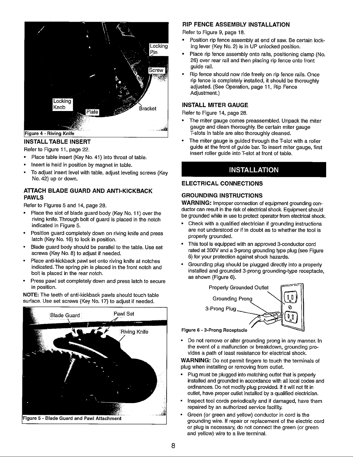
Figure 4 - Riving Knife
INSTALL TABLE INSERT
Referto Figure 11, page 22.
° Place table insert (Key No.41) into throat of table.
• Insert is held in position by magnet in table.
• To adjust insert level with table, adjust leveling screws (Key
No. 42) up or down.
ATTACH BLADE GUARD AND ANTI-KICKBACK
PAWLS
Refer to Figures5 and 14, page 28.
• Placethe slot ofbladeguardbody (Key No.11) overthe
riving knife.Throughbolt ofguardis placed inthe notch
indicatedinFigure5.
• Positionguardcompletelydownon rivingknifeand press
latch (KeyNo. 16) to lockin position.
° Bladeguardbody should be parallel tothe table.Useset
screws(Key No.8) toadjustifneeded.
• Place anti-kickbackpawlset ontorivingknifeat notches
indicated.The springpinisplacedin thefront notchand
bolt isplaced inthe rearnotch.
° Presspawlset completelydownand presslatchtosecure
in position.
NOTE:The teethofanti-kickback pawls should touchtable
surface. Use set screws (KeyNo. 17) to adjust if needed.
RIP FENCE ASSEMBLY INSTALLATION
Refer to Figure 9, page 18.
° Positionrip fenceassembly at end ofsaw.Be certainlock-
ing lever(KeyNo.2) is in UP unlockedposition.
° Placerip fenceassembly ontorails,positioningclamp(No.
26) overrear rail and thenplacingripfence ontofront
guide rail.
° Ripfence should now ride freely on ripfence rails. Once
rip fence is completely installed, it should be thoroughly
adjusted. (See Operation, page 11, Rip Fence
Adjustment.)
INSTALL MITER GAUGE
Referto Figure 14, page 28.
° The mitergauge comespreassembled.Unpackthe miter
gaugeand cleanthoroughly.Be certain mitergauge
T-slotsin tableare alsothoroughlycleaned.
° The mitergaugeisguidedthroughtheT-slotwitha roller
guideat the frontofguidebar. To insertmiter gauge,first
insertrollerguideintoT-slotat front oftable.
ELECTRICAL CONNECTIONS
GROUNDING INSTRUCTIONS
WARNING: improperconnectionofequipmentgroundingcon-
ductorcanresultintheriskofelectricalshock.Equipmentshould
begroundedwhileinusetoprotectoperatorfrom electricalshock.
• Check witha qualifiedelectrician ifgroundinginstructions
are not understoodor if in doubtas towhetherthetool is
properlygrounded.
• Thistoolisequippedwithan approved3-conductorcord
ratedat 300V anda 3-pronggroundingtypeplug(see Figure
6) for yourprotectionagainst shock hazards.
• Grounding plug should be pluggeddirectlyintoa properly
installedand grounded3-pronggrounding-typereceptacle,
as shown (Figure6).
Properly Grounded Outlet
Grounding Prong
iBlade Guard Pawl Set
3-Prong Plug ___
Figure 6 - 3-Prong Receptacle
° Do not remove or alter grounding prong in any manner. In
the event of a malfunction or breakdown, grounding pro-
vides a path of least resistance for electrical shock.
WARNING: Do not permit fingers to touch the terminals of
plug when installing or removing from outlet.
• Plug must be plugged into matching outlet that is properly
installed and grounded in accordance with all local codes and
ordinances. Do not modify plug provided. If it will not fit in
outlet, have proper outlet installed by a qualified electrician.
° Inspect tool cords periodically and if damaged, have them
repaired by an authorized service facility.
• Green (or green and yellow) conductor in cord is the
grounding wire. If repair or replacement of the electric cord
or plug is necessary, do not connect the green (or green
and yellow) wire to a live terminal.
8
Where a 2-prong wall receptacle is encountered, it must be
replaced with a properly grounded 3-prong receptacle
installed in accordance with National Electric Code and
local codes and ordinances.
WARNING: This work should be performed by a qualified
electrician.
A temporary 3-prong to 2-prong grounding adapter (see
Figure 7) is available for connecting plugs to a two pole outlet
if it is properly grounded.
Grounding Lug Make Sure
This Is
Adapter Connected To
3-Prong Plug A Known
Ground
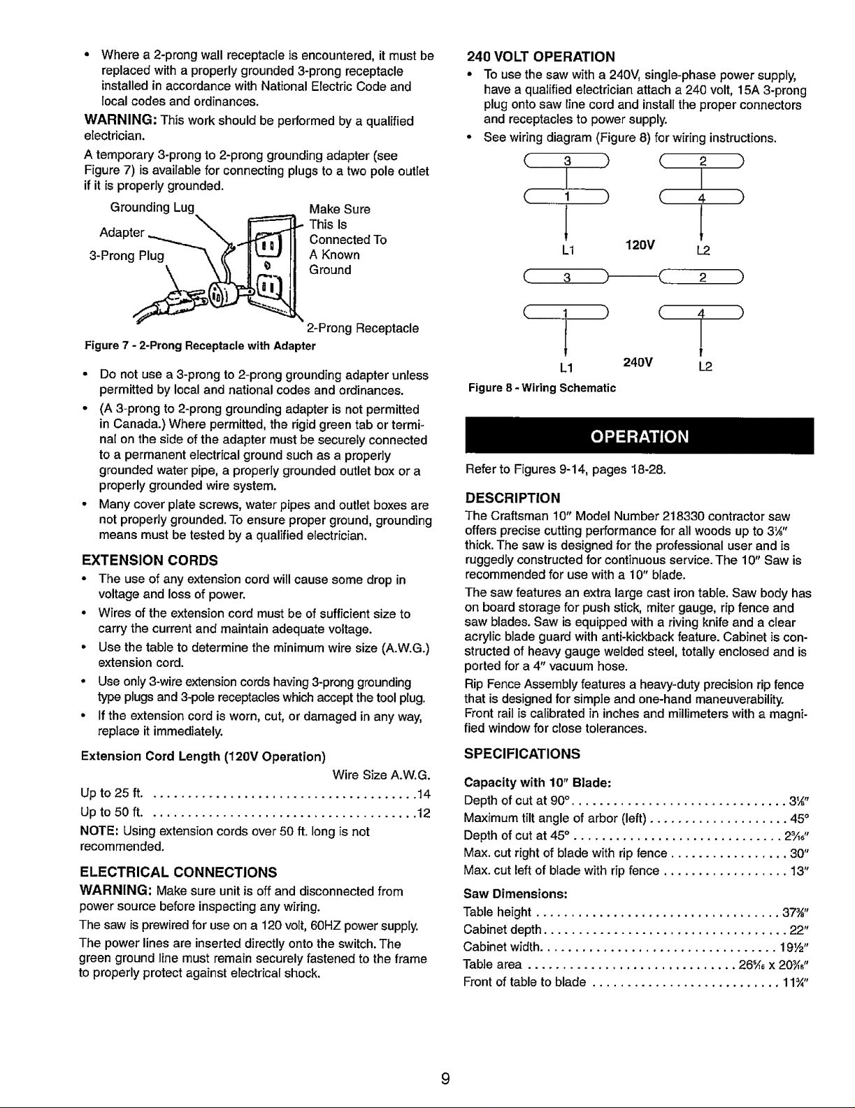
240 VOLT OPERATION
° To use the saw with a 240V, single-phase power supply,
have a qualified electrician attach a 240 volt, 15A 3-prong
plug onto saw line cord and install the proper connectors
and receptacles to power supply.
• See wiring diagram (Figure 8) for wiring instructions.
3 ) ( 2 )
I I
1 ) (. 4 )
L
L1 120V L2
(.. 3
2 )
2-Prong Receptacle
Figure 7 - 2-Prong Receptacle with Adapter
° Do not use a 3-prong to 2-prong grounding adapter unless
permitted by local and national codes and ordinances.
° (A 3-prong to 2-prong grounding adapter is not permitted
in Canada.) Where permitted, the rigid green tab or termi-
nal on the side of the adapter must be securely connected
to a permanent electrical ground such as a properly
grounded water pipe, a properly grounded outlet box or a
properly grounded wire system.
° Many cover plate screws, water pipes and outlet boxes are
not properly grounded. To ensure proper ground, grounding
means must be tested by a qualified electrician.
EXTENSION CORDS
° The use of any extension cord will cause some drop in
voltage and loss of power.
° Wires of the extension cord must be of sufficient size to
carry the current and maintain adequate voltage.
• Use the table to determine the minimum wire size (A.W.G.)
extension cord.
° Use only 3-wire extension cords having 3-prong grounding
type plugs and 3-pole receptacles which accept the tool plug.
• If the extension cord is worn, cut, or damaged in any way,
replace it immediately.
Extension Cord Length (120V Operation)
Wire Size A.W.G.
Up to 25 ff....................................... 14
Up to 50 ft....................................... 12
NOTE: Using extension cords over 50 ft. long is not
recommended.
ELECTRICAL CONNECTIONS
WARNING: Make sure unit is off and disconnected from
power source before inspecting any wiring.
The saw is prewired for use on a 120 volt, 60HZ power supply.
The power lines are inserted directly onto the switch. The
green ground line must remain securely fastened to the frame
to properly protect against electrical shock.
( 1 )
( 4 )
1
kl
Figure 8 -Wiring Schematic
Refer to Figures 9-14, pages 18-28.
DESCRIPTION
The Craftsman 10" Model Number 218330 contractor saw
offers precise cutting performance for all woods up to 3_"
thick. The saw is designed for the professional user and is
ruggedly constructed for continuous service. The 10" Saw is
recommended for use with a 10" blade.
The saw features an extra large cast iron table. Saw body has
on board storage for push stick, miter gauge, rip fence and
saw blades. Saw is equipped with a riving knife and a clear
acrylic blade guard with anti-kickback feature. Cabinet is con-
structed of heavy gauge welded steel, totally enclosed and is
ported for a 4" vacuum hose.
Rip Fence Assembly features a heavy-duty precision rip fence
that is designed for simple and one-hand maneuverability.
Front rail is calibrated in inches and millimeters with a magni-
fied window for close tolerances.
240V
SPECIFICATIONS
Capacity with 10" Blade:
Depth of cut at 90°. .............................. 3'_"
Maximum tilt angle of arbor (left) .................... 45°
Depth of cut at 45° . ............................. 2¾,"
Max. cut right of blade with rip fence ................. 30"
Max. cut left of blade with rip fence .................. 13"
Saw Dimensions:
Table height ................................... 37¾"
Cabinet depth ................................... 22"
Cabinet width.................................. 19Y2"
Table area .............................. 26'/, x 20_,"
Front of table to blade ........................... 11¾"
L2
9
 Loading...