

Page 1
Sears Brands Management Corporation, Hoffman Estates, IL 60179 U.S.A.
www.sears.com/craftsman
31624.00 Draft (10/08/09)
Assembly Instructions
10″
CONTRACTOR TABLE SAW
Model No.
351.218330
Page 2
2
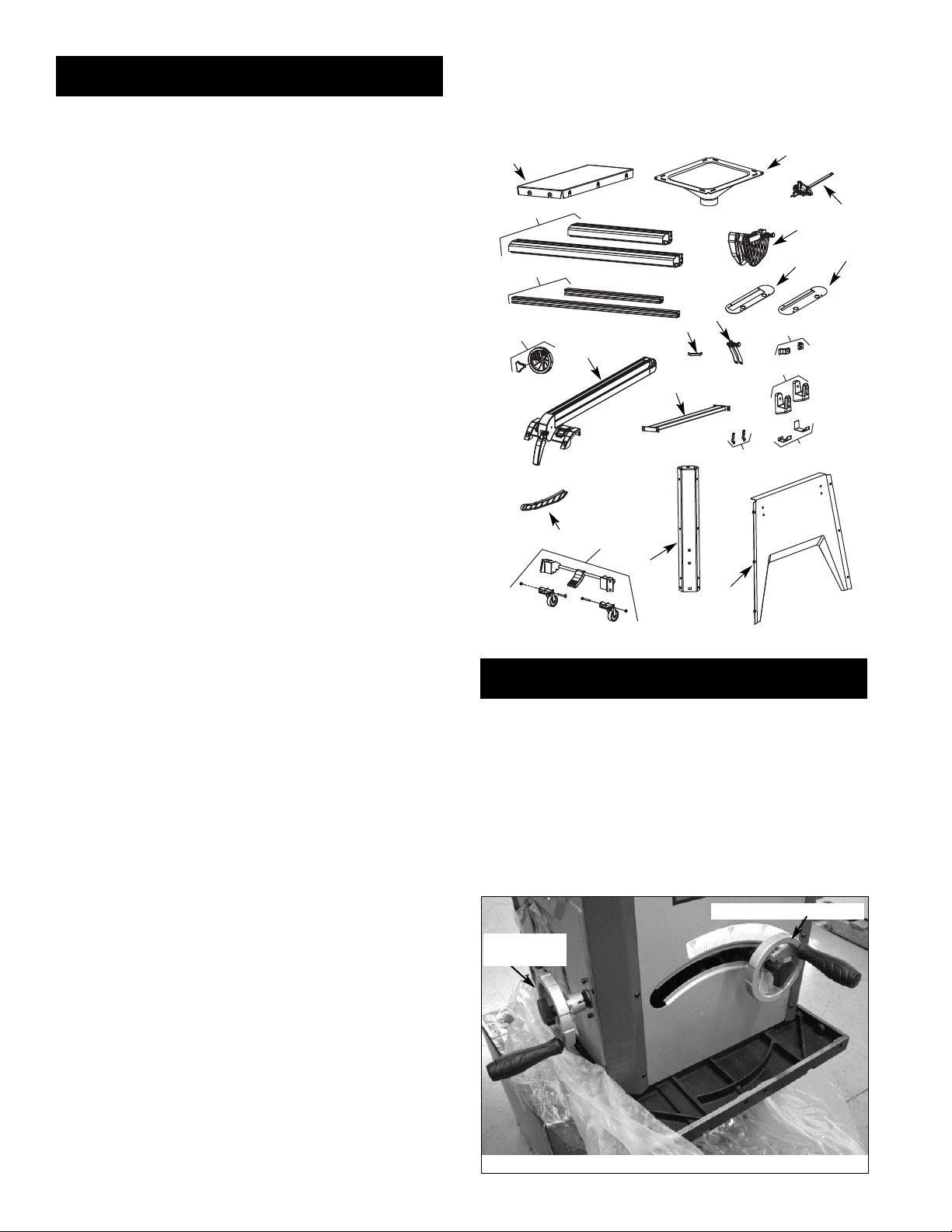
UNPACKING
The table saw body comes assembled as one unit. Additional
parts which need to be fastened to the saw should be located
and accounted for before assembling:
A Extension Table (2)
B Dust Chute
C Front Rail (2)
D Rear Rail (2)
E Miter Gauge Assembly
F Blade Guard Assembly
G Dado Insert
H Table Insert
I Handwheel Assembly with Knob (2)
J Rip Fence Assembly
K Rubber Foot (4)
L Anti-kickback Pawl Assembly
M Line Cord Hooks (2)
N Brace
O Rip Fence Storage Hooks (2)
P Blade Guard Storage Hooks (2)
Q Push Stick Storage Hooks (2)
R Push Stick
S Base Panel (4)
T Corner Support (4)
U Caster Set (2)
Hardware Bag #1
M10 x 25 Socket Head Bolt (6)
M10 Lock Washer (6)
M10 Flat Washer (6)
Hardware Bag #2
M8 x 28 Hex Head Bolt (8)
M8 x 25 Hex Head Bolt (8)
M8 x 20 Hex Head Bolt (4)
M8 Lock Washer (20)
M8 Flat Washer (20)
M8 Hex Nut (16)
M8 Acorn Hex Nut (4)
Hardware Bag #3
M6 x 16 Hex Head Screw (2)
M6 Flat Washer (2)
M6 Hex Nut (2)
M6 Lock Washer (2)
Hardware Bag #4
M10 x 25 Socket Head Bolt (4)
M8 x 16 Socket Pan Head Screw (8)
M6 x 12 Socket Pan Head Screw (24)
M6 x 16 Socket Head Bolt (2)
M5 x 12 Socket Head Bolt (4)
M3 x 10 Pan Head Screw (4)
M10 Lock Washer (4)
M6 Hex Nut (2)
M5 Lock Washer (4)
M3 Lock Washer (4)
M10 Flat Washer (4)
M6 Flat Washer (2)
M5 Flat Washer (4)
M3 Flat Washer (4)
Hardware Bag #5
10/13mm Open End Wrench
4mm Hex Wrench
5mm Hex Wrench
8mm Hex Wrench
STEP 1
INSTALL HANDWHEELS
• Remove saw cabinet and place upside down on carboard
box or cardboard on floor.
• Place one of the handwheels onto the blade raise/lower
shaft located on the front of the cabinet. Align the groove
in the back of the handwheel with the pin.
• Thread the locking knob onto the threaded end of the shaft.
• Repeat the steps above to assemble the remaining handwheel and locking knob onto the blade tilt shaft located on
the side of the cabinet.
© Sears, Roebuck and Co.
Figure 1 - Unpacking
F
G
H
I
J
K
M
N
L
A
B
P
S
U
T
Q
R
O
C
E
D
Figure 2
Blade Raise Handwheel
Blade Tilt
Handwheel
Page 3
3
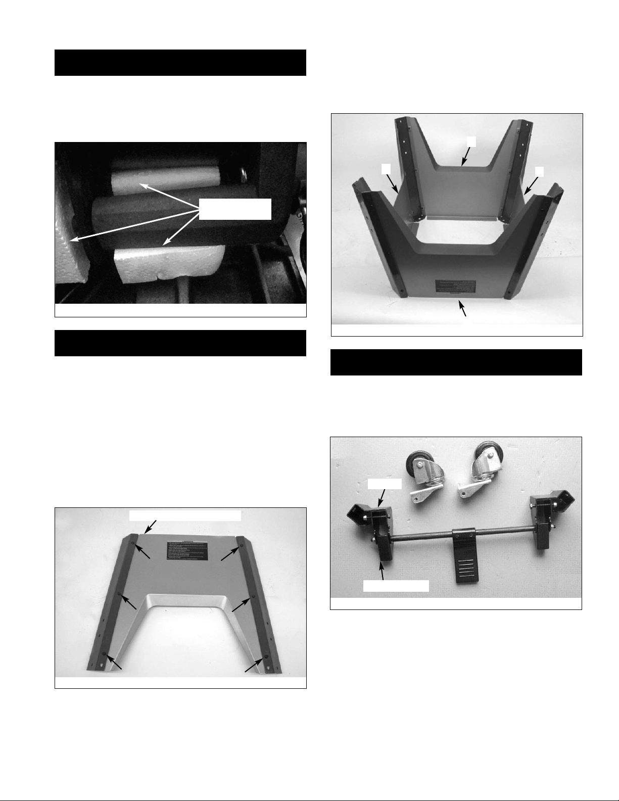
STEP 2
• Use the blade tilt handwheel to tilt the blade completely to
45°.
• Remove the packing material from behind the motor.
• Return blade to the 0° position.
STEP 3
ASSEMBLE MOBILE BASE PANELS
Tools Required: 4mm Hex Wrench
Hardware Required: Twenty-four M6 x 12 socket pan head
bolts (Hardware bag #4).
• Attach the front panel between the two corner supports
using six M6 x 12 socket pan head bolts.
Note: Place the panel edges INSIDE the corner support
surfaces.
Note: Front panel and rear panel are both stamped ‘A’.
Front panel has warning label.
• Repeat above step for the rear panel.
• Set both panel assemblies upside down on bench and
attach the left side panel (stamped ‘B’) to the assemblies
made above.
• Attach the right side panel (stamped ‘C’) to the assembly.
Below is completed base assembly.
STEP 4
ASSEMBLE CASTER SETS
Tools Required: Two 1⁄2″ Open End Wrenches
• Refer to Figure 6; remove casters (4) and supports (2)
from carton.
Figure 4
Figure 5
Letter Stamp On Top Edge
Figure 3
Remove this
packing material
A
A
Kick Plate Cam
Bracket
B
C
Figure 6
Page 4
4
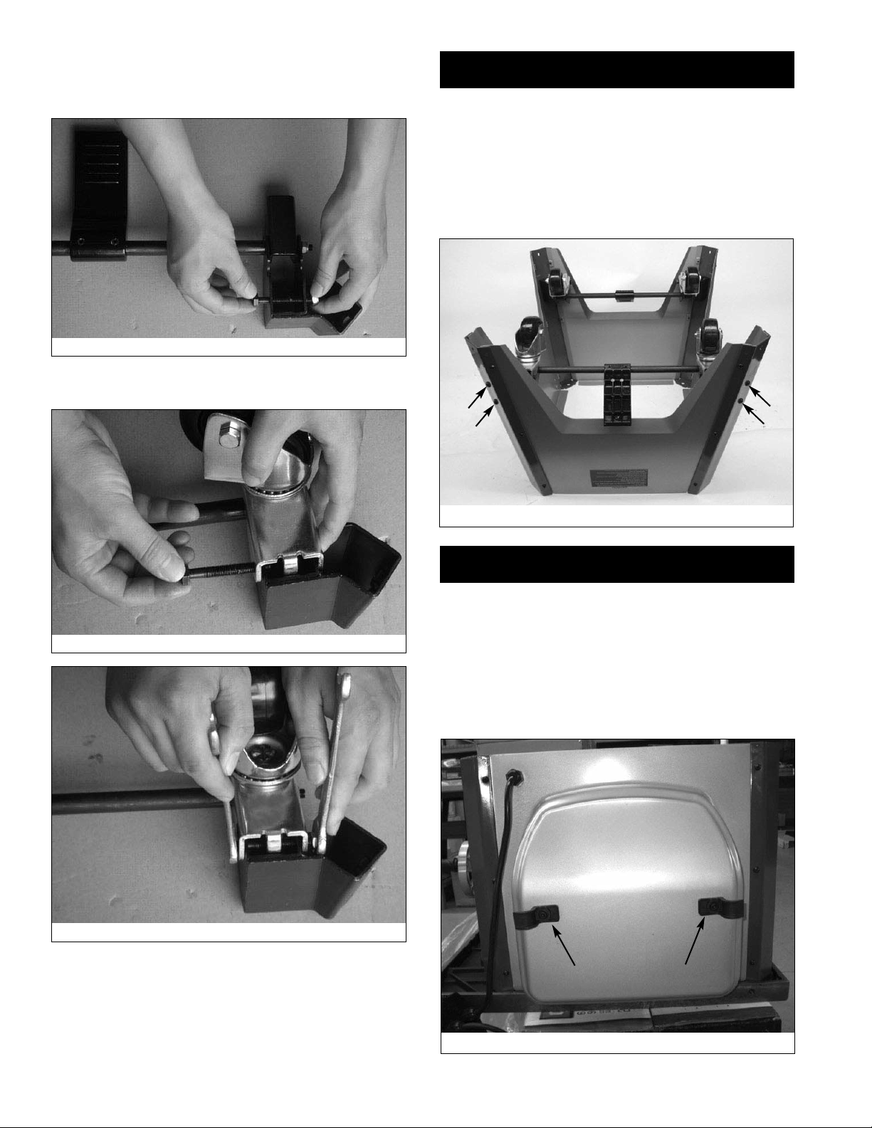
• Refer to Figure 7; loosen and remove the bolt and hex nut
from the support. Rotate foot pedal bar so that kick plate
cam is inside bracket. The kick plate cam must be underneath the caster to function properly.
• Refer to Figure 8 and 9; place caster onto the support and
secure in position with bolt and hex nut.
• Repeat above steps for the second caster set.
STEP 5
ATTACH CASTER SETS TO BASE
Tools Required: 5mm Hex Wrench
Hardware Required: Eight M8 x 16 socket pan head bolts
(Hardware bag #4).
• Attach one caster set to the two front corner supports
using four M8 x 16 socket pan head bolts.
• Attach the remaining caster set to the two rear corner
supports.
STEP 6
ATTACH LINE CORD HOOKS
Tools Required: 4mm Hex Wrench
Hardware Required: Two M6 x 16 socket pan head screws,
two M6 flat washers and two M6 hex nuts (Hardware bag #4).
• Insert a screw into a line cord hook and place against the
holes on the left side of the saw cabinet.
• Secure hook in position using flat washer and hex nut.
• Repeat for other hook.
Figure 7
Figure 8
Figure 9
Figure 10
Figure 11
Page 5

5
STEP 7
ATTACH BASE TO CABINET
Tools Required: 8mm Hex Wrench
Hardware Required: Four M10 x 25 socket head bolts, four M10
lock washers and four M10 flat washers (Hardware bag #4).
• Place dust chute over the cabinet as shown. Make sure
the holes in the corners are aligned with the slots in the
dust chute.
• Place the base assembly over the dust chute and secure
the base assembly to the cabinet using the flat washers,
lock washers and bolts.
• Secure all fasteners in the base assembly fully tight.
STEP 8
ATTACH RIP FENCE BRACKETS
Tools Required: 4mm Hex Wrench
Hardware Required: Two M6 x 16 socket head bolts, two M6
flat washers and two M6 hex nuts (Hardware bag #4).
Install the rip fence storage brackets to the right side panel of
the base using two screws, flat washers and hex nuts.
STEP 9
BLADE GUARD AND PUSH STICK STORAGE
BRACKETS
Tools Required: Phillips screwdriver and 4mm hex wrench
Hardware Required: Four M3 x 10 pan head screws, four M3
lock washers, four M3 flat washers, four M5 x 12 socket head
bolts, four M5 lock washers and four M5 flat washers
(Hardware bag #4).
• Install the push stick storage brackets to the left side panel
of the base using four screws, lock washers and flat washers.
• Install the blade guard storage brackets to the left side
panel of the base using four screws, lock washers and flat
washers.
• Press the four rubber feet to the base legs.
• Turn the saw upright.
Figure 12
Figure 13
Figure 14
Rubber Feet
Blade Guard
Bracket
Push Stick
Bracket
Figure 15
Page 6

STEP 10
ATTACH EXTENSION TABLES
Tools Required: 13mm Open End Wrench and Straight Edge
Hardware Required: Six M10 x 25 hex head bolts, six M10
lock washers and six M10 flat washers (Hardware bag #1).
• Assemble extension table to the table using hex head
bolts, lock washers and flat washers.
• Hand tighten only. Do not tighten completely until tables
are level. Use a straightedge to level tables.
• Repeat above procedure for the other extension table.
• Use a straight edge to check level and flatness between
main and extension tables.
• After tables are adjusted level and flat, secure the extension tables by tightening the hex nuts completely.
STEP 11
INSTALL BLADE
Tools Required: 13mm Open end Wrench
• Loosen knob on right side of cabinet.
• Remove blade and wrench. Replace knob.
• Depress arbor lock and use wrench to loosen flange nut.
Remove flange and nut from arbor.
• Place blade on arbor. Make sure arrow on blade and teeth
point towards front of saw.
• Replace flange and nut on arbor and securely snug blade
in position.
STEP 12
CHECK TABLE ALIGNMENT
• Saws are shipped from the factory with the table adjusted
so the miter gauge slots are parallel to the saw blade.
However, in order to obtain the best results from the saw, it
is suggested this adjustment be checked before operating.
• A simple method of checking alignment is as follows: Bolt
or clamp a dowel rod or similar object to miter gauge (a
combination square can be substituted). Pick out a tooth
on front of blade and set the dowel to it so it is just touching. Move same tooth to back of blade.
• Gauge this tooth with the dowel rod. If the tooth is in the
same position, relative to the miter gauge slot, the table is
parallel with the blade. In short, the miter gauge slots must
be parallel with the blade. This means that when measuring distance between blade and slot at the front and rear
of the blade, the distances will be equal (see Figure 20).
NOTE: Be positive to measure the distance or make the test
on the same tooth of the saw blade in both front and rear
positions.
• If an adjustment is necessary, proceed as follows: (Refer
to Figure 13 in operator’s manual). Loosen the hex head
bolts and lock washers (Nos. 36, 37 and 38) of the trunnion. Shift trunnion until a position is found where the saw
blade is parallel to the miter gauge slots.
NOTE: Saw blade should also be centered within its table
insert opening.
6
Figure 17
Flange
Straight Edge
Nut
Figure 18
Arbor Lock
Figure 19
Page 7

• Tighten the hex head bolts and lock washers very securely.
This procedure will set the table and blade in parallel position and prevent the trunnion from shifting.
STEP 13
RAIL ASSEMBLY
Tools Required: 13mm Open end Wrench
Hardware Required: Eight M8 x 28 hex head bolts, eight M8 x
25 hex head bolts, four M8 x 20 hex head bolts, twenty M8
lock washers, twenty M8 flat washers, sixteen M8 hex nuts
and four M8 acorn nuts. (Hardware bag #2).
• Insert two M8 x 28 hex head bolts and two M8 x 25 hex
head bolts into the T-slot of the right front guide rail. (The
two longer bolts will attach to the table; the two shorter
bolts attach to the table extension.)
• Attach right front rail to the table and right table extension
using flat washers, lock washers and hex nuts.
NOTE: Hand tighten all hardware during rail assembly. Do not
completely tighten hardware until all rails are mounted.
• Attach left front rail in the same manner. (The two longer
bolts attach to the table; the two shorter bolts attach to
table extension.)
• Position rails so that rails are butted together and the joint
between rails is aligned with the blade. You may need a
mallet to lightly tap rails together. Make sure rails are completely butted together at the joint.
• Use a straight edge to check level and flatness between
right and left rail and make certain that both front rails are
parallel to the table surface..
• After front rails are adjusted level and flat, tighten the
screws completely.
• Secure all hardware completely.
• Loosen and remove six socket pan head screws and the
back panel. This will allow easier attachment of the rear rails.
• Install the rear rails in the same manner as the front rails
and align the rail joint to the blade.
• Replace back panel of the cabinet.
7
Figure 22 - Use Straight Edge to Align Rail Joint to Blade
Figure 24
Figure 20 - Aligning Miter Slots to Blade
Equal
Distances
Saw
Blade
Rear
Miter Gauge Slots
Front
M8 x 28 Bolts
M8 x 25 Bolts
Figure 21 - Right Front Rail
Figure 23
Page 8

• Attach brace to the far right end of the rails.
Simultaneously slide brace with hex bolts into the rail Tslots and secure in position using lock washers, flat washers and acorn nuts.
STEP 14
ATTACH SWITCH ASSEMBLY
Tools Required: 10mm Open end Wrench
Hardware Required: Two M6 x 16 hex head bolts, two M6 flat
washers, two M6 lock washers and two M6 hex nuts.
(Hardware bag #3).
• Insert the two M6 x 16 hex head bolts into the T-slot on the
bottom of the left front rail. Position bolts approximately 6 to
8″ from the left end of the rail.
• Attach switch assembly to bolts and secure in position with
flat washers, lock washers and hex nuts.
STEP 15
POSITION AND ADJUST RIVING KNIFE
• Riving knife is installed on the saw. Raise the blade completely to access the riving knife.
• Loosen the locking knob and raise the riving knife to its
highest position. Riving knife has three holes for three positions. The highest position is for all thru cuts. The middle
position is for rabbets and other non-thru cuts, (with guard
and pawls removed). The lowest position is for dado cuts.
• Make sure locking pin is aligned with riving knife hole and
secure in position by tightening locking knob.
• Riving knife must be in line with blade. Make sure riving
knife sits flat against mounting bracket and lock plate.
RIVING KNIFE TO BLADE ADJUSTMENT
• Riving knife to blade clearance: the gap between the riving
knife and the saw blade should be an even distance
across the entire radius.
• The riving knife should also be in line with the saw blade. If
adjustment is necessary:
1. Locate the riving knife bracket.
2. Loosen the two socket head cap screws slightly enough
to move the bracket bringing the riving knife in line with
the saw blade making sure the gap between the blade
and knife is even and from
1
⁄4 to 5⁄16″ in distance.
3. Once the riving knife is aligned with the blade, tighten
the socket head cap screws.
STEP 16
INSTALL TABLE INSERT
• Place table insert into throat of table.
• Insert is held in position by magnet in table.
• To adjust insert level with table, adjust leveling screws up
or down.
8
Figure 25
Figure 26
Figure 28
Figure 27 - Riving Knife
Locking
Pin
Bracket
Plate
Locking
Knob
Screw
Leveling Screws
Page 9

STEP 17
ATTACH BLADE GUARD AND ANTI-KICKBACK
PAWLS
• Place the slot of blade guard body over the riving knife.
Slot of bushing is placed in the notch indicated in Figures
29 and 30.
• The bushings have a beveled edge and must be located in
the center of the slot to lock properly.
• Position guard completely down on riving knife and press
latch to lock in position.
• Blade guard body should be parallel to the table. Use set
screws to adjust if needed.
• Place anti-kickback pawl set onto riving knife at notches
indicated. The spring pin is placed in the front notch and
bolt is placed in the rear notch.
• Press pawl set completely down and press latch to secure
in position.
NOTE: The teeth of anti-kickback pawls should touch table
surface. Use set screws to adjust if needed.
STEP 18
INSTALL MITER GAUGE
• The miter gauge comes preassembled. Unpack the miter
gauge and clean thoroughly. Insert into storage slots on
right side of cabinet.
9
Figure 29 - Blade Guard and Pawl Attachment
Blade Guard
Pawl Set
Riving Knife
Figure 30
Bushing
Figure 31 - Latches Lock and Unlock Blade Guard and Pawls
to Riving Knive
Set Screws
Latches
Figure 32
Page 10

STEP 19
INSTALL PUSH STICK
• Insert the push stick into brackets on left side of base.
STEP 20
INSTALL RIP FENCE
• Position rip fence assembly at end of saw. Be certain locking lever is in UP unlocked position.
• Place rip fence assembly onto rails, positioning clamp over
rear rail and then placing rip fence onto front guide rail.
• Rip fence should now ride freely on rip fence rails. Once
rip fence is completely installed, it should be thoroughly
adjusted.
STEP 21
SAW COMPLETELY ASSEMBLED
10
Figure 33
Figure 35
Figure 34
Page 11

11
NOTES
Page 12

Get it fixed, at your home or ours!
Your Home
For expert troubleshooting and home solutions advice:
www.managemyhome.com
For repair – in your home – of all major brand appliances,
lawn and garden equipment, or heating and cooling systems,
no matter who made it, no matter who sold it!
For the replacement parts, accessories and
owner’s manuals that you need to do-it-yourself.
For Sears professional installation of home appliances
and items like garage door openers and water heaters.
1-800-4-MY-HOME
Call anytime, day or night (U.S.A. and Canada)
www.sears.com www.sears.ca
®
(1-800-469-4663)
Our Home
For repair of carry-in items like vacuums, lawn equipment,
and electronics, call anytime for the location of your nearest
Sears Parts & Repair Service Center
1-800-488-1222 (U.S.A.) 1-800-469-4663 (Canada)
www.sears.com www.sears.ca
To purchase a protection agreement on a product serviced by Sears:
1-800-827-6655 (U.S.A.) 1-800-361-6665 (Canada)
Para pedir servicio de reparación
a domicilio, y para ordenar piezas:
1-888-SU-HOGAR
(1-888-784-6427)
®
Au Canada pour service en français:
1-800-LE-FOYER
(1-800-533-6937)
www.sears.ca
MC
® Registered Trademark / TM Trademark /SM Service Mark of Sears Brands, LLC
® Marca Registrada / TM Marca de Fábrica / SM Marca de Servicio de Sears Brands, LLC
MC
Marque de commerce / MD Marque déposée de Sears Brands, LLC © Sears Brands, LLC
 Loading...