

Page 1

Operator's Manual g
PLANER WITH DUST COLLECTION
Model No.
13" I
351.217430
CAUTION: Read and follow
all Safety Rules and Operating
Instructions before First Use
of this Product.
Sears, Roebuck and Co., Hoffman Estates, IL 60179 U.S.A.
www.sears.con_craftsman
18236.03 Draft (07/01/04)
Page 2
Warranty.................................... 2
Safety Rules ............................... 2-3
Unpacking .................................. 3
Assembly ................................. 3-4
Installation ................................. 4-5
Operation ................................. 6-9
Maintenance .............................. 9-11
Troubleshooting ........................... 12-13
Parts Illustration and List ................... 14-19
Espa_ol ................................. 20-31
FULL ONE YEAR WARRANTY
Ifthis product fails due toa defect inmaterial or work-
manship within oneyear from the date of purchase,
Sears will at its option repair or replace itfree of
charge. Contact your nearest Sears Service Center
(1-800-4-MY-HOME) to arrange for productrepair,or
returnthisproductto place of purchase for replacement.
If this product is used for commercial or rental purpos-
es, this warranty will applyfor 90 days from the date of
purchase.
This warranty applies only while this product is used in
the United States.
This warrantygives you specificlegal dghts and you may
also have other rights which vary from stateto state.
Sears, Roebuck and Co., Dept. 817WA, Hoffman
Estates, IL 60179
WARNING: For yourown safety, read all of the rules
and precautions before operating tool.
CAUTION: Always follow proper operating procedures
as defined in this manual even ifyou are familiar with
use of this or similar tools. Remember that being care-
less for even a fraction of a second can result in severe
personal injury.
BE PREPARED FOR JOB
• Wear proper apparel. Do not wear loose clothing,
gloves, neckties, rings, bracelets or other jewelry
which may get caught inmoving parts of machine.
• Wear protective hair covering to contain long hair.
• Wear safety shoes with non-slip soles.
• Wear safety glasses complying with United States
ANSI Z87.1. Everyday glasses have only impact
resistant lenses. They are NOT safety glasses.
• Wear face mask or dust mask if operation is dusty.
• Be alert and think clearly Never operate power tools
when tired, intoxicatedor when taking medications
that cause drowsiness.
© Sears, Roebuck and Co.
PREPARE WORK AREA FOR JOB
• Keep work area clean. Cluttered work areas invite
accidents.
• Do not use power tools in dangerous environments.
• Do not use power toots in damp or wet locations.Do
not expose power tools to rain.
• Work area should be properly lighted.
• Proper electrical receptacle shouldbe availablefor
tool. Three prong plug should be plugged directly
into properly grounded, three-prong receptacle.
• Extension cords should have a grounding prong and
the three wires of the extension cord shouldbe of
the correct gauge.
• Keep visitors at a safe distance from work area.
• Keep childrenout of workplace. Make workshop child-
proof. Use padlocks, master switches or remove switch
keys to prevent any unintentional use of power tools.
TOOL SHOULD BE MAINTAINED
• Always unplugtool priorto inspection.
• Consult manual for specificmaintainingand adjust-
ing procedures.
• Keep toollubricatedand clean for safest operation.
• Remove adjustingtools.Form habitof checkingto
see that adjustingtools are removed before switch-
ingmachine on.
• Keep all parts in working order. Check to determine
that the guard or other parts will operate properly
and perform their intended function.
• Check for damaged parts. Check for alignment of
moving parts, binding, breakage, mounting and any
other condition that may affect a tool's operetlon.
• A guard or other part that is damaged should be
properly repaired or replaced. Do not perform
makeshift repairs. (Use parts list provided to order
replacement parts.)
KNOW HOW TO USE TOOL
• Use right tool for job. Do not force tool or attachment
to do a job for which it was not designed.
• Disconnect tool when changing blades.
• Avoid accidental start-up. Make sure that the switch
is in the OFF position before plugging in.
• Do not forcetool. It will work most efficientlyat the
rate for which it was designed.
• Keep hands away from moving parts and cutting
surfaces.
• Never leave tool runningunattended. Turn the power
offand do not leave tool untilit comes to a complete
stop.
• Do notoverreach. Keep proper footingand balance.
• Neverstandontool.Seriousinjurycould occurif tool is
tipped or if blade is unintentionally contacted.
• Know your tool. Learn the tool's operation, applica-
tion and specific limitations.
2
Page 3
• Use recommended accessories (refer to page 15).
Use of improper accessories may cause risk of
injuryto persons.
• Handle workpiece correctly.Protect handsfrom
possible injury.
• Turn machine off if it jams. Blade jams when it digs
too deeply into workpiece. (Motor force keeps it
stuck in the work.)
• Always keep drive, cutterhead and blade guards in
place and in proper operating condition.
• Feed work into blade or cutter against direction of
rotation.
CAUTION: Think safety! Safety is a combinationof
operator common sense and alertness at all times
when tool is being used.
WARNING: Do not attempt to operate tool untit it is
completely assembled according to the instructions.
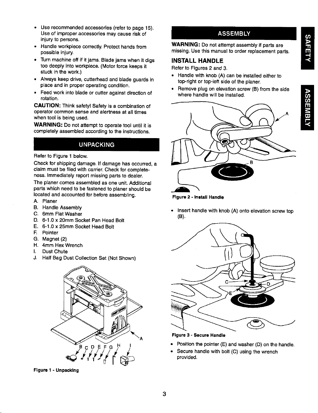
Refer to Figure 1 below.
Check for shipping damage. If damage has occurred, a
claim must be filed with carrier. Check for complete-
ness. immediately report missing partsto dealer,
The planer comes assembled as one unit. Additional
parts which need to be fastened to planer should be
tocated and accounted for before assembling.
A. Planer
B. Handle Assembly
C. 6ram Flat Washer
D. 6-1.0 x 20mm Socket Pan Head Bolt
E. 6-1.0 x 25mm Socket Head Bolt
F. Pointer
G. Magnet (2)
H. 4ram HexWrench
I. Dust Chute
J. Half Bag Dust Collection Set (Not Shown)
WARNING: Do not attempt assembly if parts are
missing. Use this manual to order replacement parts,
INSTALL HANDLE
Refer to Figures 2 and 3.
• Handle with knob (A) can be installedeither to
top-right or top-left side of the planer,
• Remove plug on elevation screw (B) from the side
where handle will be installed.
Figure 2 - Install Handle
• Insert handle with knob (A) onto elevation screw top
(B).
Figure 1 - Unpacking
Figure3 - Secure Handle
• Positionthe pointer (E) and washer (D) on the handle.
• Secure handle with bolt (C) usingthe wrench
provided,
Page 4
INSTALL DUST CHUTE
Refer to Figure 22.
• Slide dust chute (Key No. 10) over fan housing(Key
No. 8). Secure in positionwith bolt (Key No 9).
• Attachthe Half Bag Dust CollectionSet (included)
after mounting planer to work surface.
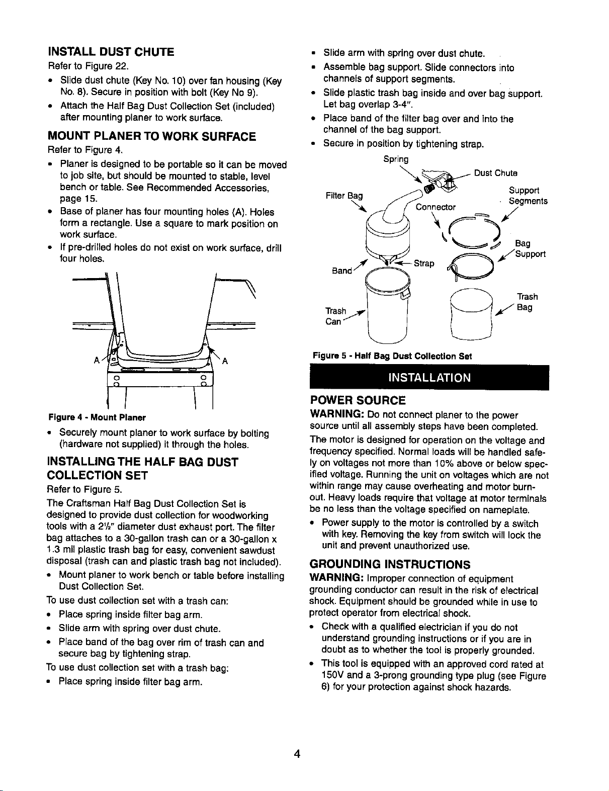
MOUNT PLANER TO WORK SURFACE
Refer to Figure 4.
• Planer is designed to be portable so itcan be moved
to job site, butshould be mountedto stable, level
bench or table. See Recommended Accessories,
page 15.
• Base of planer has four mounting holes (A). Holes
form a rectangle. Use a square to mark position on
work surface.
• If pre-drilled holes do not exist on work surface, drill
four holes.
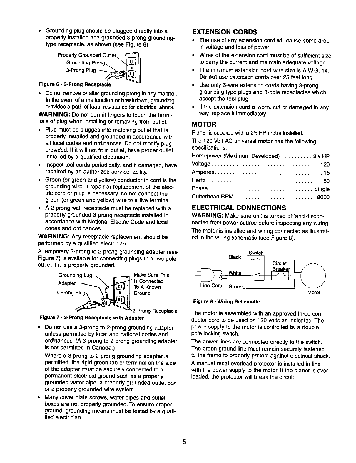
• Slide arm withspring over dust chute.
• Assemble bag support. Slide connectorsinto
channels of support segments:
• Slide plastic trash bag inside and over bag support.
Let bag overlap 3-4".
• Place band of the filter bag over and into the
channel of the bag support.
• Secure in position by tightening strap.
Figure4 - MountPlaner
• Securely mount planer towork surface by bolting
(hardware not supplied) itthrough the holes.
INSTALLING THE HALF BAG DUST
COLLECTION SET
Refer to Figure 5.
The Craftsman Half Bag Dust CoUection Set is
designed to provide dust collection for woodworking
tools with a 2%" diameter dust exhaust port. The filter
bag attaches to a 30-gaUon trash can or a 30-gallon x
1.3 mil plastic trash bag for easy, convenient sawdust
disposal (trash can and plastic trash bag not included).
• Mount planer to work bench ortable before installing
Dust Collection Set,
To use dust collection set with a trash can:
• Place spring insidefilter bag arm.
• Slide arm with spring over dust chute.
• Place band of the bag over rim oftrash can and
secure bag by tightening strap.
To use dust collection set with a trash bag:
• Place spring inside filter bag arm.
Figure 5 - Half Bag Dust Collection Set
POWER SOURCE
WARNING: Do not connectplaner to the power
source untilall assembly steps have been completed.
The motoris designedfor operationon the voltage and
frequency specified. Normal loads willbe handledsafe-
lyon voltages not more than 10% above or below spec-
ified voltage. Running the uniton voltageswhichare not
within range may cause overheating and motor burn-
out. Heavy loads require that voltage at motor terminals
be no less than the voltage specifiedon nameplate.
• Power supply to the motor is controlled by a switch
with key.Removing the key from switch will lock the
unit and prevent unauthorized use.
GROUNDING INSTRUCTIONS
WARNING: Improper connection of equipment
groundingconductorcan result in the riskof electrical
shock.Equipment shouldbe groundedwhile in use to
protectoperatorfrom electrical shock.
• Check with a qualified electricianifyou do not
understand groundinginstructionsor if you are in
doubt as to whether the tool is properlygrounded.
• This tool isequipped withan approved cord rated at
150V and a 3-prong groundingtype plug (see Figure
6) for your protectionagainst shockhazards.
Page 5
• Grounding plug should be plugged directly into a
properly installed and grounded 3-prong grounding-
type receptacle, as shown (see Figure 6).
Properly Grounded Outlet _
Grounding Prong ®11
3-Prong Plug __
Figure 6 - 3-Prong Receptacle
• Do not remove or alter grounding prong in any manner.
In the event of a malfunction or breakdown, grounding
provides a path of least resistance for electrical shock.
WARNING: Do not permit fingers to touch the termi-
nals of plug when installing or removing from outlet.
• Plug must be plugged into matching outlet that is
properly installed and grounded in accordance with
all local codes and ordinances. Do not modify plug
provided. If it will not fit in outlet, have proper outlet
installed by a qualified electrician.
• Inspect tool cords periodically, and if damaged, have
repaired by an authorized service facility.
• Green (or green and yellow) conductor in cord is the
grounding wire. If repair or replacement of the elec-
tric cord or plug is necessary, do not connect the
green (or green and yellow) wire to a live terminal.
• A 2-prong wall receptacle must be replaced with a
properly grounded 3-prong receptacle installed in
accordance with National Electric Code and local
codes and ordinances.
WARNING: Any receptacle replacement should be
performed by a qualified electrician.
A temporary 3-prong to 2-prong grounding adapter (see
Figure 7) is available for connecting plugs to a two pole
outlet if it is properly grounded.
Grounding Lug _ Make Sure This
-- - _ m.--..---rr is Connected
P,oapTer _''"_ _'t"_-J[I ToAKnown
3-Prong __ _.. J Ground
"/'_ _;_v't_'l _"_2-Prong Receptacle
Figure 7 - 2-Prong Receptacle with Adapter
• Do not use a 3-prong to 2-prong grounding adapter
unless permitted by local and national codes and
ordinances. (A 3-prong to 2-prong grounding adapter
is not permitted in Canada.)
Where a 3-prong to 2-prong grounding adapter is
permitted, the rigid green tab or terminal on the side
of the adapter must be securety connected to a
permanent electrical ground such as a properly
grounded water pipe, a properly grounded outlet box
or a properly grounded wire system.
• Many cover plate screws, water pipes and outlet
boxes are not properly grounded. To ensure proper
ground, grounding means must be tested by a quali-
fied electrician.
EXTENSION CORDS
• The use of any extensioncord will cause some drop
involtage and loss of power.
• Wires ofthe extensioncord mustbe of sufficientsize
to carry the current and maintain adequate voltage.
• The minimum extension cord wire size is A.W.G. 14.
Do not use extension cords over 25 feet long.
• Use only 3-wire extension cords having 3-prong
grounding type plugs and 3-pole receptacles which
accept the tool plug.
• If the extension cord is worn, cut or damaged in any
way, replace it immediately.
MOTOR
Planeris suppliedwith a 2+/2HP motorinstalled.
The 120 Volt AC universalmotorhas the following
specifications:
Horsepower (Maximum Developed) .......... 2V2HP
Voltage ................................... 120
Amperes................................... 15
Hertz ..................................... 60
Phase.................................. Single
Cutterhead RPM .......................... 8000
ELECTRICAL CONNECTIONS
WARNING: Make sure unit is turned offand discon-
nected from power source before inspectingany wiring.
The motoris installedand wiringconnected as illustrat-
ed in the wiringschematic (see Figure 8).
Black
Switch
Circuit
Breaker
Line Cord
Motor
Figureg- WiringSchematic
The motor is assembled with an approved three con-
ductor cord to be used on 120 volts as indicated. The
power supply to the motor is controlled by a double
pole locking switch.
The power lines are connected directly to the switch.
The green ground line must remain securely fastened
to the frame to properly protect against electrical shock.
A manual reset overload protector is installed in line
with the power suppry to the motor. If the planer is over-
loaded, the protector will break the circuit.
5
Page 6
DESCRIPTION
Craftsman 13" planer finishes rough-cutlumber to size
and planes soft and hardwoods up to 6" thick and 13"
wide. Wood feeds into two-blade cutterhead by rubber
infeed/outfeed rollers. Sturdy base construction and
four-post design permits smooth feeding and virtually
snipeless planing. Planer comes with enclosed, univer-
sal ball bearing, 2_/2HP (max. developed) motor with
overload protection. Motor has ON/OFF switch with
removable key to prevent accidental start-up. Unit fea-
tures rollercase lock for uniform thickness, power move-
ment control for rollercase, depth-of-cut gauge for con-
venient set-up, workpiece thickness pre-set gauge with
6 settings for consistent set-up, easy hands-free
replacement of blades for safety and minimized down-
time, built-in dust collector, top mounted rollers for
workpiece return, built-in carrying handles, cord wraps
for portability and folding infeed/outfeed rollers for
smooth operation. Planer takes cuts up to _/_"per pass
at 24 feet per minute. Inch height scale has graduations
in _A6"increments, and metric height scale has gradua-
tions in lmm increments.
MOTOR
Table Size ........................... 13" x 10%"
Blade Width ............................... 13"
Maximum Depth of Cut ..................... 3/32"
Cuts Per Minute ......................... 16,000
Dust Collection Port......................... 2V2"
Overall Dimensions........ 21" H x 26_/2" W x 35V2"D
Motor ............... 2V2HP (max, dev,), 15A, 120V
Weight ................................. 97 Ibs
• Do not plug in planer unless switch is in off position.
After turning switch on, allow planer to come to full
speed before operating.
• Keep hands clear of all moving parts.
• Do not force cut. Slowing or stalling will overheat
motor. Allow automatic feed to function properly.
• Use quality lumber. Blades last longer and cuts are
smoother with good quality wood.
• Do not plane material shorter than 15", narrower
than 3A",wider than 13" or thinner than '/8".
• Never make planing cut deeper than 3/,,.
• Maintain the proper relationships of infeed and out-
feed table surfaces and cutterhead blade path.
• Do not back the work toward the infeed table.
• Take precautions against kickback. Do not permit any-
one 1ostand or cross in line of cutterhead's rotation.
Kickback or thrown debris will travel in this direction.
• Turn switch off and disconnect power whenever plan-
er is not in use.
• Replace knives as they become damaged or dull.
• Keep planer maintained. Follow maintenance instruc-
tions (see pages 9 -11).
OPERATING CONTROLS
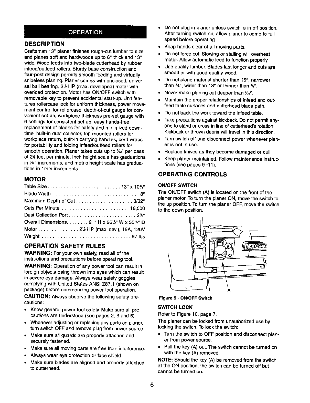
ON/OFF SWITCH
The ON/OFF switch (A) is located on the front of the
planer motor. To turn the planer ON, move the switch to
the up position. To turn the planer OFF, move the switch
to the down position.
OPERATION SAFETY RULES
WARNING: For yourown safety,read all of the
instructions and precautionsbefore operatingtool
WARNING: Operation of any power toolcan resultin
foreignobjectsbeing thrown into eyes whichcan result
in severe eye damage. Always wear safety goggles
complying with United States ANSI Z87.1 (shown on
package) before commencing power tool operation.
CAUTION: Always observe the following safety pre-
cautions:
• Know general power tool safety.Make sure all pre-
cautions are understood (see pages 2, 3 and 6).
• Whenever adjusting or replacing any parts on planer,
turn switch OFF and remove plug from power source.
• Make sure all guards are properly attached and
securely fastened.
• Make sure all moving parts are free from interference.
• Always wear eye protection or face shield.
• Make sure blades are aligned and properly attached
to cutterhead.
Figure 9 - ON/OFF Switch
SWITCH LOCK
Refer to Figure 10, page 7.
The planer can be lockedfrom unauthorizeduse by
lockingthe switch.To lock the switch:
• Turnthe switchto OFF positionand disconnect plan-
er from powersource.
• Pull the key (A) out.The switch cannot be turned on
with the key (A) removed.
NOTE: Shouldthe key (A) be removedfrom the switch
at the ON position,the switchcan be turned offbut
cannot be turned on.
Page 7
B
Figure10 - Switch Lockand Circuit Reset
• Toreplace key, slidekey intothe slot on switch until
it snaps.
CIRCUIT BREAKER
Refer to Figure 10.
The planer isequipped with a motor protection device-
circuitbreaker. The breaker will automaticallyshut the
planer off when excessive current is consumed.
Ifthe breaker is tripped, turn the planer off and reset
the circuitby pressingthe button(B).
CAUTION: Be sure to turn the planer off priorto reset-
tingthe circuitbreaker to avoid unintentionalstart-up of
the planer.
A rotationaldirection label with depth indicatoris pro-
vided on bothsides of the planer top.
The English/Metricscale (D) with pointerallowseasy
adjustment of relier case height.
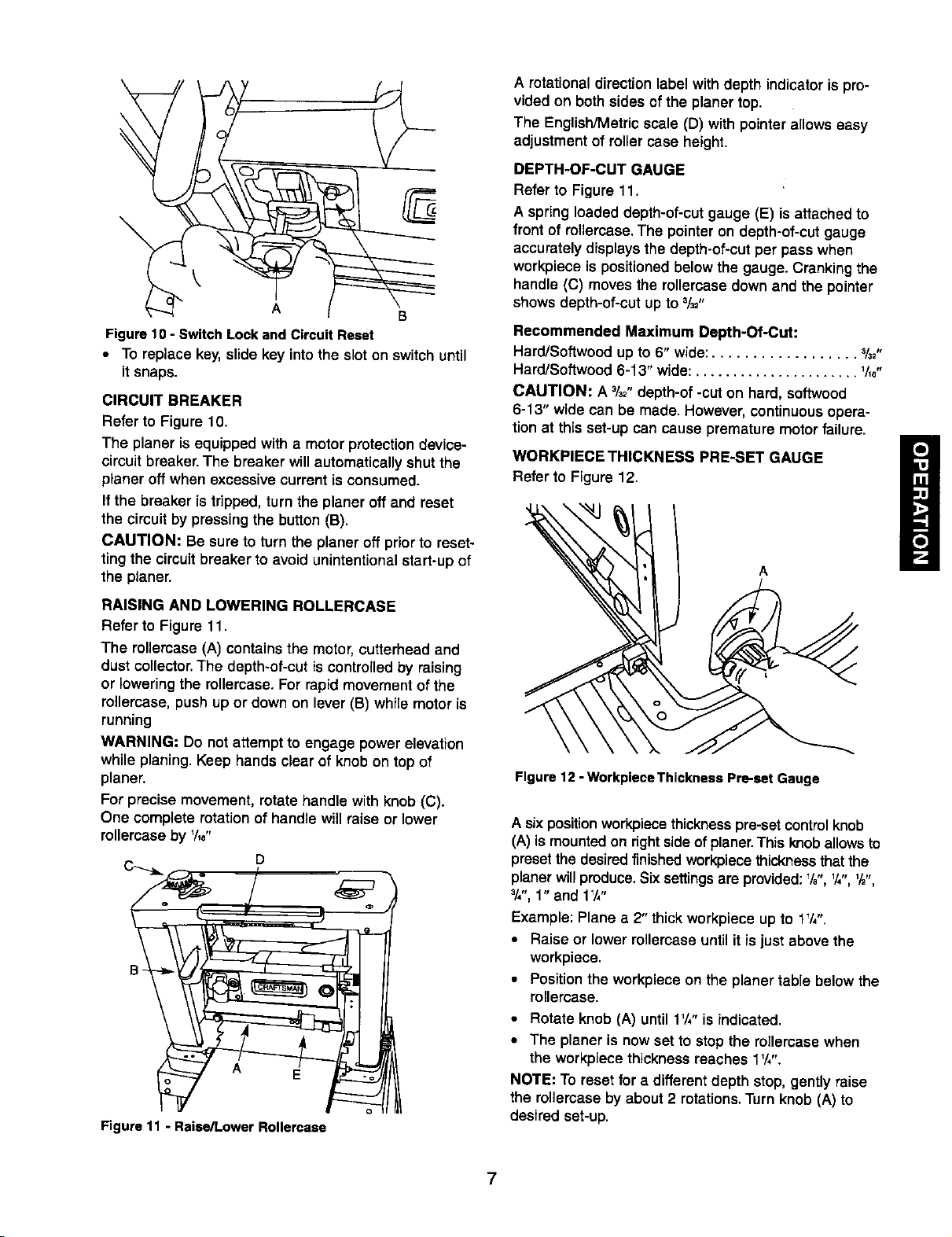
DEPTH-OF-CUT GAUGE
Refer to Figure 11.
A spring loaded depth-of-cut gauge (E) is attached to
front of rollercase. The pointer on depth-of-cut gauge
accurately displays the depth-of-cut per pass when
workpieca is positioned below the gauge. Cranking the
handle (C) moves the rollercase down and the pointer
shows depth-of-cut up to 3/=,,
Recommended Maximum Depth-Of-Cut:
Hard/Softwood up to 6" wide:.................. %2"
Hard/Softwood 6-13" wide: ...................... V_e"
CAUTION: A 3/_,,depth-of -cuton hard, softwood
6-13" wide can be made. However, continuousopera-
tion at this set-up can cause premature motorfailure.
WORKPIECE THICKNESS PRE-SET GAUGE
Refer to Figure 12.
A
RAISING AND LOWERING ROLLERCASE
Refer to Figure 11.
The rellercase (A) containsthe motor,cutterhead and
dust collector.The depth-of-cut is controlledby raising
or lowering the rellercase. For rapid movementof the
rellercase, push up or down on lever (BI while motor is
running
WARNING: Do notattempt to engage power elevation
while planing.Keep handsclear of knobon top of
planer.
For precise movement, rotate handle with knob (C).
One complete rotationof handle will raise or lower
rollercaseby %6"
Figure 11 - Raise/Lower Rollercase
Figure 12 -Workpisce Thickness Pre-set Gauge
A six position workpiecethickness pre-setcontrolknob
(A) ismountedon rightside of planer.This knoballowsto
presetthe desiredfinished workpiecathicknessthatthe
planerwillproduce.Sixsettingsare provided:%", Y,",'/_",
_/,",1" and 1W'
Example: Plane a 2" thickworkpiece up to 1_/,".
• Raise or lowerrollercase until it is just above the
workpiece.
• Positionthe workpiece on the planer table belowthe
rollercase.
• Rotate knob (A) until 1V,"is indicated.
• The planer is nowset to stopthe roilercase when
the workpiecethickness reaches 1V,".
NOTE: To reset for a differentdepth stop,gently raise
the rollercase byabout 2 rotations.Turnknob (A) to
desired set-up.
7
Page 8
ROLLERCASELOCK
Refer to Figure 13.
The rollercase can be locked from any movementdur-
ing planing in order to guarantee uniform thickness. To
lock rollercase, pull down on lever (A).
Figure 13 - Ronercase Lock
To release rollercase, gently push up lever (A)
NOTE: The rollercasecan be raised or lowered when it
is locked by exerting excessivepressure on handle.
However, cranking the handle when the rollercaseis
lockedwillwear down the locking mechanism prema-
turely.
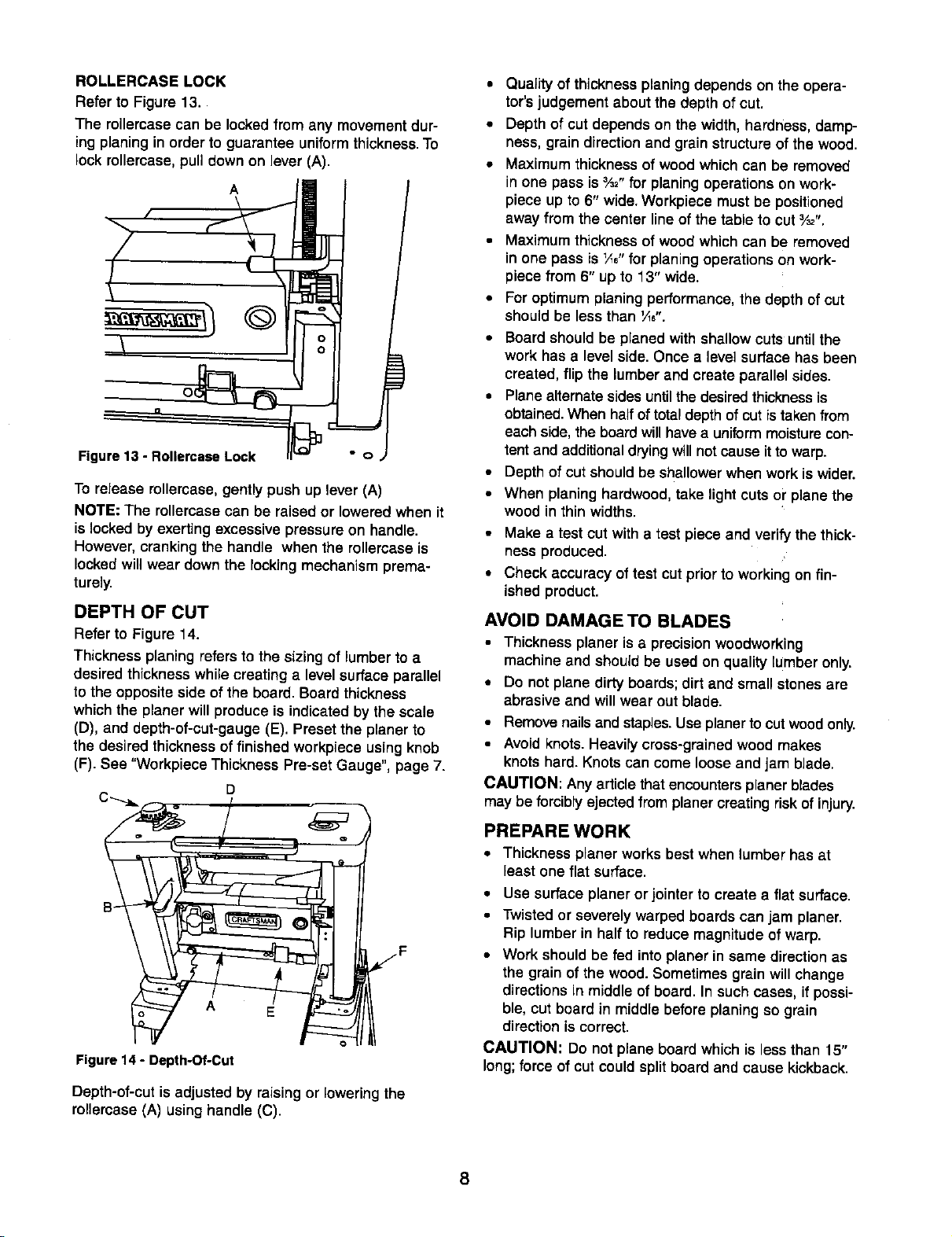
DEPTH OF CUT
Refer to Figure 14.
Thickness planing refers to the sizing of lumber to a
desired thicknesswhile creating a level surface parallel
to the opposite side of the board. Board thickness
whichthe planer will produce is indicated by the scale
(D), and depth-of-cut-gauge (El. Preset the planer to
the desired thickness of finished workpiece using knob
(F). See "Workpiece Thickness Pre-set Gauge", page 7.
D
• Quality of thickness planing depends on the opera-
tor's judgement about the depth of cut.
• Depth of cut depends on the width, hardness, damp-
ness, grain direction and grain structure of the wood.
• Maximum thickness of wood which can be removed
in one pass is 3/=,,for planing operations on work-
piece up to 6" wide. Workpiece must be positioned
away from the center line of the table to cut _/=".
• Maximum thickness of wood which can be removed
in one pass is _," for planingoperations on work-
piece from 6" up to 13" wide.
• For optimum planing performance, the depth of cut
should be less than '/1,".
• Board should be planed with shallow cuts until the
work has a level side. Once a level surface has been
created, flip the lumber and create parallel sides.
• Planealternatesides until the desired thickness is
obtained.When halfof totaldepth of cut istaken from
each side,the boardwillhavea uniformmoisturecon-
tentand additionaldryingwill notcause ittowarp.
• Depth of cut shouldbeshallowerwhen work is wider.
• When planing hardwood, take lightcuts or plane the
wood in thin widths.
• Make a test cut with a test piece and verifythe thick-
ness produced.
• Check accuracy of test cut prior to working on fin-
ished product.
AVOID DAMAGE TO BLADES
• Thickness planer is a precisionwoodworking
machine and shouldbe used on quality lumber only,
• Do not plane dirtyboards;dirt and small stones are
abrasive and willwear out blade,
• Removenailsand staples.Useplanerto cutwoodonly.
• Avoidknots.Heavilycress-grethedwood makes
knots hard. Knotscan come loose and jam blade.
CAUTION: Anyarticlethat encountersplaner blades
may be forciblyejected from planercreating riskofinjury,
Figure 14 - Depth-Of-Cut
Depth-of-cutis adjusted by raisingor lowering the
rollercase (A) using handle (C).
PREPARE WORK
• Thickness planer works best when lumber has at
least one flat surface.
• Use surface planer orjointerto create a flat surface.
• Twistedor severely warped boards can jam planer.
Rip lumber in half to reduce magnitude of warp.
• Work shouldbe fed intoplaner in same directionas
the grain of the wood. Sometimes grain will change
directions in middle of board. In such cases, if possi-
ble, cut board in middle before planing so grain
direction is correct.
CAUTION: Do not plane board which is less than 15"
long;force of cut couldsplitboard and cause kickback.
8
Page 9
FEEDINGWORK
The planerissuppliedwithplaningbladesmountedinthe
cutterheadand infeedandoutfeedrollersadjustedtothe
correctheight.Planerfeed isautomatic;itwillvary slightly
depending on typeofwood.
• Feed rate refers to rate at which lumber travels
through planer.
• Operator is responsiblefor aligning work so it will
feed properly.
• Raise/lower rottercaseto produce the depth ol cut
desired.
• Stand on side towhich the handle is attached.
-!
Figure15 - FeedingWork
• Boards longerthan 24" shouldhave additionalsup-
port from free standing materiat stands.
• Positionthe workpiece with the face to be planed on
top,
• Turnthe planer on.
• Rest board end on in-feed roller plate and direct
board into planer.
• Gently slide workpiece into the infeed side of the
planer until the infeed roller begins to advance the
workpiece.
• Let go of the workpieca and allow automatic feed to
advance the workpieca.
• Do not push/pull on workpiece. Move to the rear and
receive planed lumber by grasping itin same man-
ner as it was fed.
CAUTION: To avoid risk of injury due to kickbacks, do
not stand directly in line with front or rear of planer,
• Do not grasp any portion of board which has not
gone past out-feed roller.
• Repeat this operation on all boards which need to be
same thickness.
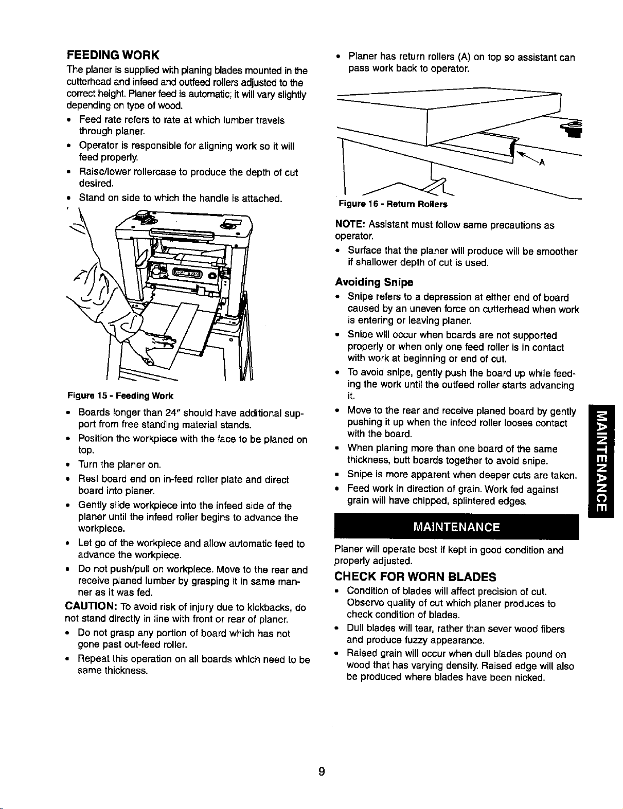
• Planer has return rollers (A) on top so assistant can
pass work back to operator.
Figure 16 - Return Rollers
NOTE: Assistantmustfollow same precautions as
operator.
• Surface thatthe planer willproducewill be smoother
ifshallowerdepth of cut is used.
Avoiding Snipe
• Snipe refers to a depression at either end of board
caused by an uneven force on cutterhead when work
is entering or leaving planer.
• Snipe will occur when boards are not supported
properly or when only one feed roller is in contact
with work at beginning or end of cut.
• To avoid snipe, gently push the board up while feed-
ing the work until the outfeed rotterstarts advancing
it.
Move to the rear and receive planed board by gently
pushing it up when the infeed roller looses contact
with the board.
• When planing more than one board of the same
thickness, butt boards together to avoid snipe.
• Snipe is more apparent when deeper cuts are taken.
• Feed work in direction of grain. Work fed against
grain will have chipped, splintered edges.
Planer willoperate best if kept in good conditionand
properly adjusted.
CHECK FOR WORN BLADES
• Conditionof blades willaffect precisionof cut.
Observe quality of cutwhich planer producesto
check conditionof blades.
• Dull bladeswilltear, rather than sever woodfibers
and producefuzzy appearance.
• Raised grain willoccurwhen dull blades poundon
wood that has varying density.Raised edge willalso
be prm:luced where blades have been nicked.
9
Page 10
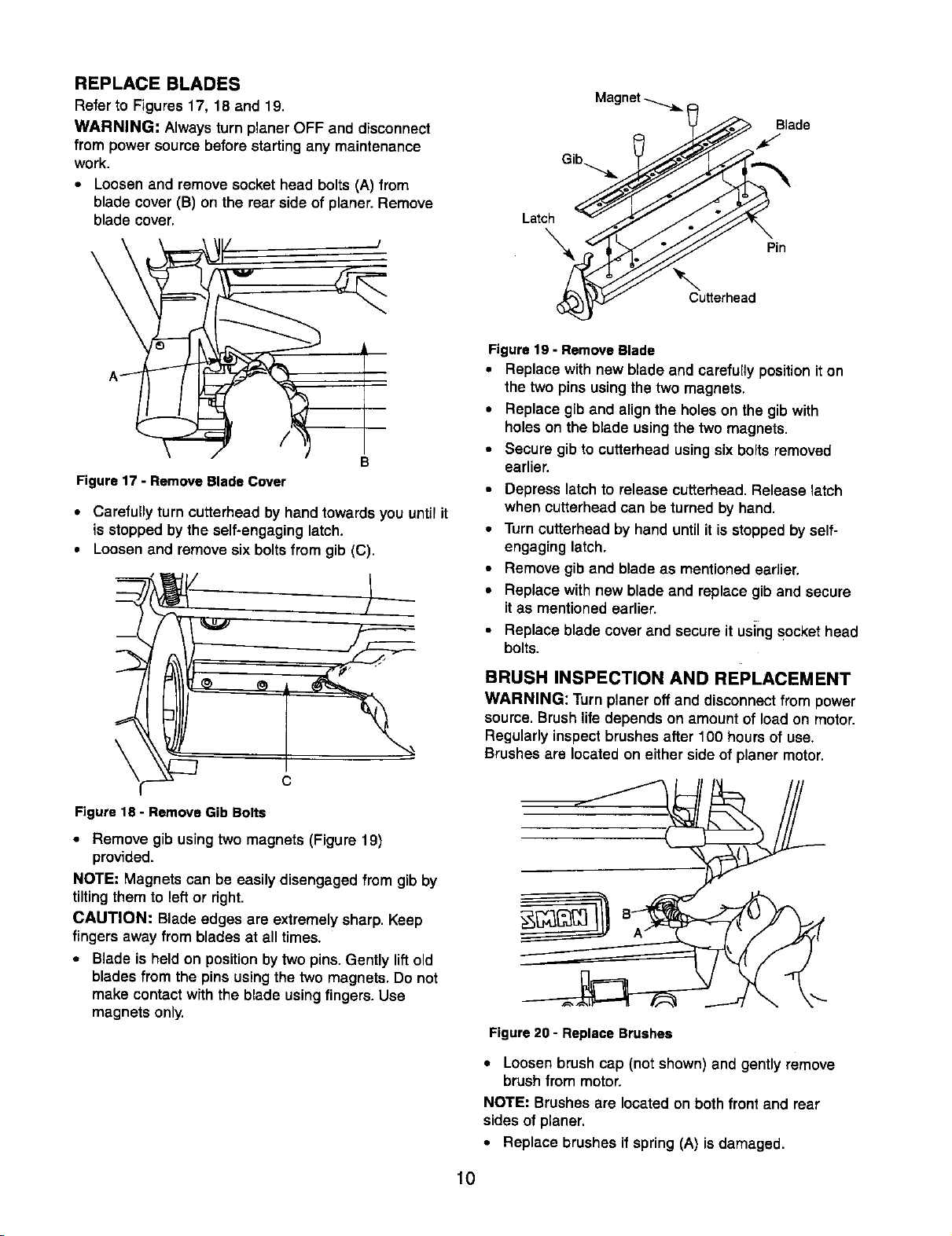
REPLACE BLADES
Refer to Figures 17, 18 and 19.
WARNING: Always turn planer OFF and disconnect
from power source before starting any maintenance
work.
• Loosen and remove socket head bolts (A) from
blade cover (B) on the rear side of planer.Remove
blade cover.
A/
B
Figure17 - RemoveBlade Cover
• Carefully turn cutterhead by hand towards you until it
is stopped by the self-engaging latch.
• Loosen and remove six bolts from gib (C).
Magnet
Blade
Latcx_kS
Figure19 - RemoveBlade
• Replace with new blade and carefullyposition it on
the two pins using thetwo magnets.
• Replace gib and align the holeson the gib with
holeson the blade using the two magnets,
• Secure gib to cutterhead usingsix boltsremoved
earlier.
• Depress latch to release cutterhead. Release latch
when cutterhead can be turned by hand.
• Turncutterhead by hand until it is stopped by self-
engaging latch,
• Remove gib and blade as mentioned earlier.
• Replace with new blade and replace giband secure
itas mentioned earlier.
• Replace blade cover and secure it usingsockethead
bolts.
Figure 18 - Remove Gib Bolts
• Remove gib using two magnets (Figure 19)
provided.
NOTE: Magnets can be easily disengaged from gib by
tiltingthem to leftor right.
CAUTION: Blade edges are extremely sharp. Keep
fingers away from blades at all times.
• Blade is held on position by two pins. Gently lift old
blades from the pins using the two magnets. Do not
make contact with the blade using fingers. Use
magnets only.
BRUSHINSPECTION AND REPLACEMENT
WARNING: Turn planer off and disconnect from power
source. Brushlife depends on amount of load on motor,
Regularly inspect brushes after 100 hours of use.
Brushes are located on either side of planer motor.
Figure 20 - Replace Brushes
• Loosen brush cap (not shown) and gently remove
brush from motor.
NOTE: Brushes are located on both front and rear
sides of planer.
• Replace brushes if spring (A) is damaged.
10
Page 11

• Replace brushes if carbon (B) is worn.
• Replace brushes and tighten brush cap.
ADJUSTING ROLLERCASE LEVEL
Refer to Figures 21 and 22, pages 14and 16.
The planer will produceuneven depthof cut (tapered
cut) if rollemase (Fig. 22, Key No. 59) is not parallel
with base (Fig. 21, Key No. 48). To restore parallelism of
rollercasewith base:
• Using a test piece, measure height of the taper.
• Turnplaner offand disconnect from power source.
• Fold front and rear extensiontables.
• Lay planer carefully on itsback so that bottom side
of base is facing you.
• Loosentwo socket head bolts (Fig.21, Key No. 62).
Loosen chain (Fig. 21, Key No.67) bysliding idler
bracket (Fig. 21, KeyNo. 60).
• Rotate elevationscrews as needed. Each turn of
screw will movethat side of rollercase by _Aa".
• Retighten chain using idler bracket.Tighten socket
head bolts securely.
• Set planer back on itsbase.
• Make a test cut toverify adjustment.
REPLACING V-BELT
Refer to Figures 21, 22 and 23, pages 14, 16 and 18.
Inadequate tension in V-belts (Fig 22, Key No. 28 and
Fig. 23, Key No.78) will cause belts to slip from the pul-
leys. Loose belts must be replaced. To replace V-belts:
• Remove socket pan head screw and flat washer
(Fig. 21, Key Nos. 1 and 2). Pull handle off. Pull knob
(Fig. 21, Key No. 40) off.
• Remove four pan head screws (Fig. 21, Key No. 15)
from cover (Fig. 21, Key No. 10). Remove cover.
Remove right side cover (Fig. 21, Key No. 39).
• Remove V-belt (Fig. 22, Key No. 28) by walkingthe
belt from both pulleys alternately. Gently pull the belt
while turning the pulleys at the same time. Repeat
with V-belt (Fig. 23, Key No. 78).
• Replace with new belts. Walk each belt onto the pul-
leys in the reverse manner as when removingthe
belts.
Make sure each of the belts are evenly seated all
the way on both pulleys.
Replace right side panel and knob. Replace cover
and secure with pan head screws. Replace handle
and secure with flat washer and pan head screw.
LUBRICATION
• Motorand cutterhead bearings are sealed and need
no lubrication.
Gears and elevation screws should be cleaned of
debris and greased.
The table and extension tables can be coated with a
lubricant such as paste wax, to make the workpiece
feed smoother. Be sure the lubricant used does not
affect the ability to finish the workpiece with varnish,
sealer, etc. Do not use any siliconebase lubricants.
CLEAN PLANER
• Keepplaner cleanof any wood chips,dust,dirt ordebris.
• After 10 hours of operation, the chains and gears
should have wood chips, dust and old grease
removed.
• Use common automotive bearing grease to lubricate
all chains and gears. Be sure all chains and gears
have plenty of grease.
11
Page 12

SYMPTOM
Snipe
(gouging at ends of board)
Fuzzy grain Planing wood with a high moisture Remove high moisture content from woodby
Torn grain 1.Too heavy a cut 1.Review "Depth of Cut"
Rough raised grain 1.Dull blades 1.Replace blades per instructions.
Uneven depth of cut Rollercase not level with planer Rollercase not level
side to side) base See "Adjusting Table Level"
Rollercase elevation adjusts
with difficulty
POSSIBLE CAUSE(S)
1.Dull blades
2.Inadequate supportof long boards
3.Uneven force on cutterhead
4.Rollercase not level with base
5.Lumber not butted properly
content drying
2.Blades cutting against grain 2.Review "Feeding Work"
3.Dull blades 3.Replace blades per instructions
2.Too heavy a cut 2.Review "Depth of Cut"
3.Moisture content too high 3.Dry the wood or use dried wood
1.Sprockets or chain dirty
2.Elevation screws, columns dirty
3.Elevation screws worn
4.Friction between rollercase and
covers
5.Rollercase not parallel with planer
base
6.Rollercase lockengaged
CORRECTIVE ACTION
1.Replace bladesper instructions,
See "Maintenance"
2,Support long boards.See "Avoiding Snipe"
3,Gently push board when board is in contact
withonlyonefeed roller,See "AvoidingSnipe"
4,Adjust rollercase
See "Adjusting Table Level"
5,Butt end to end each piece of stock as
boards pass through planer
See "Maintenance"
See "Maintenance"
1.Clean and lubricate sprocketsand chain
2.Clean and lubricateelevationscrews, columns
3.Replace elevation screws
4.Clean and lubricate
5.Adjust rollercase
See "Adjusting Table Level"
6.Release rollercase lock
Board feeds inside, but stops 1.Outfeed rollers cannot rotate due 1.Clear the clogging, cleandust collector
moving past the outfeed roller to clogging of chips system. See "Clean Planer"
2.Too much pressure on the 2.Use support stands to support workpiece
cutterhead from long workpiece longer than 24". See "Recommended
Accessories"
Board thickness does not Indicator not set correctly Adjust indicator and tighten securely
match depth of cut scale
Chain jumping 1.Sprockets worn 1.Replace sprockets
2.Chain worn 2.Replace chain
Planer will not operate 1.No power to planer 11.Check power source by qualified electrician
2.Motor overload protection tripped !2.Turn planer off. Reset motor overload
3.Defective or loose switch or wiring 3.Check switchand wiring by qualified
Belt slipping Loose belt Replace belt, see "Replacing V-Belt"
Rollercase connect be lowered Workpiece thickness gauge setting Reset thickness gauge setting,
restricts rollercase movements see "Workpiece Thickness Gauge"
I
protection. See "Overload Reset"
electrician
12
Page 13

SYMP/uM
Excessive dust in air
(gougingat ends of board)
Excessive fan noise
Motor overheats
Tripping circuit breaker or fuses
POSSIBLE CAUSE(S)
1.Leaking bag or hose connection
2.Collector bag leaks
1.Large debris or piece of wood in
fan housing
2.Loose fan
1.Motor overload
2.Improper motor cooling
1.Motor overload
2.Improper capacity of circuit breaker
or fuses
3.Dull blades
CORRECTIVE ACTION
1.Check collector bagconnections. Check
collectorhose connections
2.Dust trapped under bag clamp or collector
bag not sealed on flange
1.Turn collector off and let debris settlein
collector bag. Remove blade guard and
clear chamber
2.Remove blade cover and tighten bolt
(Fig. 22, Key No. 19)
1.Reduce depth ofcut
2.Clean sawdustfrom motor
1.Reduce depth of cut
2.Use proper capacity circuitbreaker or fuse
3.Replace blades
13
Page 14

Model 351.217430
Figure 21 - Replacement Parts Illustration for Base
9,
19 20 7 1_
-_1
,, 22
26 27/4
j°
56
35 36
58
38
28/_
65
68
66
54
14
Page 15

KEY
NO.
2
3
4
5
6
7
8
9
10
11
12
13
14
15
16
17
18
19
20
21
22
23
24
25
26
27
28
29
30
31
32
33
34
35
36
PART NO.
16099.00
STD851006
16098.00
16100.00
00964.00
STD652005
20042.00
16610.00
18578.00
18623.00
18524.00
09637.00
16742.00
02783.00
16096.00
16101.00
18500.00
01903.00
18566.00
05285.00
18603.00
18581.00
18565.00
07339.00
18525.00
03069.00
18583.00
18580.00
07482.00
18554.00
18516.00
18555.00
00389.00
18564,00
18619.00
18344.00
DESCRIPTION
QTY.
6-1.0 x 20ram Socket Pan Head 2
Screw
6ram Flat Washer* 2
Pointer 1
Handle Assembly 1
6-1.0 x 6ram Set Screw 1
5ram LockWasher* 4
6 x 24ram Knurled Dowel Pin 2
Spring 1
Plug 1
Upper Cover 1
6 x 21mm Knurled Dowel Pin 2
Bushing 4
Roller 2
4 x 18mm Spring Pin 1
8-1.25 x 16ram Socket Pan Head 4
Screw
Grip 2
4-1.59 x 6ram Threadforming 8
Screw
4-0.7 x 10ram Pan Head Screw 2
Bracket 1
5-0.8 x 6ram Pan Head Screw 4
Spring 1
Pointer Bracket 1
Cable 1
6mm Steel Ball 1
Collar 2
5-0.8 x 6ram Set Screw 2
Pointer Guide 1
Pointer 1
5-0.8 x 18ram Socket Head Bolt 2
Pulley Bracket 1
Bushing 2
Cable Pulley 1
5-9.8 x 12mm Pan Head Screw 1
Left Side Cover 1
Tool Storage Case 1
5-1.6 x 12ram Threadforming 4
Screw
Shaft37 18597.00 1
KEY
! NO. PART NO.
38 16115.00
39 18591.00
40 18560.00
41 18616,00
42 18547.00
43 03855.00
44 00256.00
45 18526.00
46 18527.00
47 18534.00
48 18507.00
49 STD841217
50 STD833020
51 STD840610
52 18601.00
53 08662.00
54 09658.00
55 18615.00
56 00781.00
57 18563.00
58 18535.00
59 18590.00
60 18299.00
61 STD851005
62 05331.00
63 18339.00
64 18333.00
65 05148.00
66 18618.00
67 18522.00
68 18540.00
69 STD315505
70 18510.00
71 18332.00
72 18338.00
73 STD851004
74 20036.00
75 STD841015
76 18505.00
DESCRIPTION
Magnet
RightSide Cover
Knob
Table
Guide Plate
5-0.8 x 10ram Socket Head Bolt
3AMI-20 Retaining Ring
FrontColumn
Rear Column
ElevatingScrew
Base
12-1.75mm Hex Nut*
6-1.0 x 20ram Hex Head Bolt*
6-1.0ram Hex Nut*
Spacer
6-1.0 x 8ram Socket Head Bolt
Bushing
Support Roller
4-0.7 x 8ram Pan Head Screw
Left Roller Plate
ExtensionTable
Right Roller Plate
Idler Bracket
5mm FlatWasher*
5-0.8 x 12mm Socket Head Bolt
Sprocket
Spacer
3AMI-8 Retaining Ring
Thickness Gauge
Chain
Gauge Bracket
6000ZZ Ball Bearing*
Bearing Retainer
Spacer
Sprocket
4ram Flat Washer*
4-0.7 x 12ram Socket Pan Head
Screw
10-1.5ram Hex Nut*
AdjustScrew
QTY.
2
1
1
1
2
8
2
2
2
2
1
4
4
4
4
4
4
2
12
2
2
2
1
2
6
1
1
1
1
1
1
2
2
2
2
2
2
4
4
Standard hardware item available locally
A Not Shown
Recommended Accessories
A Multi-Purpose Stand
A Horizontal Roller Stand
A Three-Roller Stand
15
9-22224
9-21417
9-22265
Page 16

Model 351.217430
Figure 22 - Replacement Parts Illustration for Rollercase
51
36
35
11 12
13
14 15
21 25
23
f
40
33
\
47 48
32
12
11
2
69
73
2-_--'P--/
43
16
34
.d,--- 41
f,
Page 17

KEY
NO.
1
2
3
4
5
6
7
10
11
12
13
14
15
16
17
18
19
20
21
22
23
24
25
26
27
28
29
30
31
32
33
34
35
36
PART NO.
18506.00
03855.00
18514.00
18499.00
01784.00
18523.00
06731.00
18537.00
18349.00
18288.00
STD840812
STD852008
16383.00
06821.00
06396.00
18568.00
16129.00
16351.00
06346.00
STD851006
18536,00
18539.00
STD315505
18599.00
18533.00
00964.00
18538.00
18495.00
16125.00
16124.00
16123.00
16382.00
03069.00
20039.00
18573.00
00964.00
DESCRIPTION
Air Duct
5-0.8 x 10mm Socket Head Bolt
Blade Cover
4-1.4 x 12mm Flat Head
ThreadformingScrew
5-0,8 x 10ram Pan Head Screw
Chip Deflector
5-0.8 x 10ram Socket Pan Head
Screw
Fan Housing
6-1.0 x25ram Socket Pan Head
Screw
Dust Chute
8-1.25mm Hex Nut*
8mm Lock Washer*
Left Cam
3CM1-12 E-Ring
3 x 12mm Spring Pin
LockLever
Spring
LockLever Cap
6-1.0 x 12mm Socket Pan Head
Screw
6ram Flat Washer*
!Ean
i Fan Shaft
6000ZZ Ball Bearing*
Spacer
Dust Cover
6-1.0 x 6mm Set Screw
Fan Pulley
135J2 V-Belt
Rod
Spring
Pad
Right Cam
5-0,8 x 6ram Set Screw
Spring
Nut
6-1.0 x 6ram Set Screw
QTY.
1
16
1
3
4
1
2
1
2
2
1
2
2
1
1
1
1
1
1
1
2
1
1
1
1
1
4
4
4
1
1
2
1
1
KEY
NO.
37
38
39
4O
41
42
43
44
45
46
47
48
49
5O
51
52
53
54
55
56
57
58
59
60
61
62
63
64
65
66
67
68
69
7O
71
72
73
74
75
PART NO.
18562.00
STD851005
08551,00
00814.00
18612.00
02702.00
18593.00
18513.00
18595.00
18589.00
05383.00
STD540501
00361.00
01474.00
18582.00
01548.00
STD851004
18579.00
18520.00
00781.00
18584.00
18574.00
18594.00
18494.00
18587.00
18636.00
18570.00
18571,00
02614,00
STD841015
18614.00
!18611.00
00533.00
STD851008
00483.00
18567.00
03853.00
03843.00
18585,00
DESCRIPTION QTY.
Left Elevating Nut 1
5ram Flat Washer* 1
Retainer Plate 1
5-0.8 x 16ram Socket Head Bolt 2
Outfeed Spring 2
Cord Clamp 1
Roller 2
Belt Guard 1
Screw 1
Right Elevating Nut 1
5-9.8 x 16mm Hex Head Bolt 5
5-0.8ram Hex Nut* 5
5-0.8 x 8ram Pan Head Screw 2
5ram Serrated Lock Washer 2
Pointer Cover 1
4-0.7 x 12ram Pan Head Screw 1
4mm Flat Washer* 1
Pointer 1
Bushing 1
4-0.7 x 8ram Pan Head Screw 2
PointerHousing 1
Nut 1
Rollercase 1
12mm Steel Ball 1
Retaining Plate 1
3-1.0 x 8ramThreadforming Screw 2
Magnet 4
Magnet Seat 4
5-0.8 x 10ram Flat Head Screw 4
10-1.5mm Hex Nut* 1
Stop Rod 1
InfeedSpring 2
3AM1-15 Retaining Ring 2
8ram Fiat Washer* 1
8-1.25 x 25mm Socket Head Bolt 1
Cable Clamp 1
Sprocket 2
RetainingBracket 4
Retainer 4
Standard hardware itemavailable locally
17
Page 18

Model 351.217430
Figure 23 - Replacement Parts Illustration for Cutterhead and Gearing
48 55
51
67
68
\
63
64
65
2-.._
3
83 84
82
@ _X 87
69
71
\7 3
.76
77 78 79
86
85
7 46
4O
44
45
35
36
37
59
J
!
26
47
18
Page 19

KEY
NO. PART NO.
1 18517.00
2 18548.00
3 00221.00
4 03855.00
8 18516.00
6 16515.00
7 18545.00
8 18551.00
9 00256.00
10 03069.00
11 18546.00
12 ST0852005
13 18598.00
14 05331.00
15 STD315505
16 18510.00
17 18332.00
18 18338.00
19 ST0851004
20 20036.00
21 18606.00
22 06182.00
23 18549.00
24 18541.00
25 18622.00
26 ST0315525
27 18542.00
28 18613.00
29 18607.00
30 97339.00
31 18519.00
32 18621.00
33 06252.00
34 18553,00
35 18497.0O
36 22548,00
37 03853.00
38 06045.00
39 ST0851005
40 18608.00
41 18617.O0
42 18600.00
43 18502.00
44 15105.00
45 18575.00
Standard hardware item available locally
A Not Shown
DESCRIPTION
Bushing
Guide Rod
3AMI-10 Retaining Ring
5-0.8 x 10rnrn Socket Head Bolt
Bushing
Bracket
Grip
Handle
3AMI-20 Retaining Ring
6-0.8 x 6ram Set Screw
Guide Bracket
5mm Lock Washer*
Sliding Bar
5-0.8 x 12rnrn Socket Head Bolt
6000ZZ Ball Bearing"
Bearing Retainer
Spacer
Sprocket
4rnrn Flat Washer*
4-0.7 x 12turn Socket Pan Head
Screw
Spring
6-1.0 x 30rnm Socket Head Bolt
Guide Rod
Gear
Transmission Seat
6002ZZ Ball Bearing"
Gear
Spring Holder
Spring
6mm Steel Ball
Bushing
Transmission Collar
5-0.8 x 14rnrn Socket Head Bolt
Holder
3AMI-24 Retaining Ring
Chain
Sprocket
5-0.8 x 20rnm Socket Head Bolt
5mrn Flat Washer*
Spring
Tension Wheel Assembly
Spacer
5-0.8 x 30turn Socket Head Bolt
5-0.8 x 35rnrn SocketHead Bolt
Outside Gear Plate
QTY.
1
1
1
4
1
1
1
1
3
2
1
2
1
2
1
1
1
1
1
1
2
2
1
2
1
2
1
4
4
4
4
1
2
1
1
1
1
1
1
1
1
1
2
4
1
KEY
NO.
PART NO. DESCRIPTION
46
20038.00
47
18596.00
48
18267.00
49
18351.00
5O
18329.00
51
20020.00
52
18577.00
53
STD315225
54
18572.00
55
18266.00
56
18277.00
57
18330.00
58
18528.00
59
19069.00
60
16529.00
61
03839.00
62
18557.00
63
18602.00
64
9-29459
65
18543,00
66
09789.00
67
18512.00
68
ST0315245
69
18509.00
7O
05331.00
71
18609.00
72
18531.00
73
20040,00
74
01784,00
75
18824,00
76
18832,00
77
18552,00
78
93841.00
79
00964,00
8O
18530.00
81
18493,00
82
20041,00
83
16080,00
84
94287,00
85
20043,00
86
20044.00
87
20045.00
A
18625,00
20026,00
18236,03
QTY.
Sleeve 2
Shaft 1
58"1"/12TGear 1
70T Gear 1
Spacer 2
Inside Gear Plate 1
Pinion Gear 1
6202ZZ Ball Bearing* 1
Motor Pulley 1
52T/12T Gear 1
Bushing 5
Spacer 4
Cover 1
4 x4x 19mm Key 1
Cutterhead 1
5 x5x 10mm Key 1
Cutterhead Pin 4
Spring 4
Blade (Set of 2) 1
Gib 2
6-1.0 x 16turn Socket Pan Head 12
Screw
Bearing Retainer 1
6204ZZ Bail Bearing* 1
Bearing Cover 1
5-0.8 x 12mm Socket Head Bolt 3
Spring 1
Cutterhead Lock 1
Bushing 1
5-0.8 x 10mm Pan Head Screw 1
Spacer 1
Cutterhead Pulley 1
Pulley Retaining Nut 1
135J6 V-Belt 1
6-1.0 x 6rnrnSet Screw 1
Cutterhead Fan Pulley 1
Motor Assembly 1
Line Cord 1
Switch 1
Circuit Breaker 1
Brush Holder 2
Brush (set of 2) 1
Brush Cap 2
Half-Bag Dust Collection Set 1
Parts Bag 1
Operator's Manual 1
19
Page 20

CEPILLADORA CON RECOLECTOR
DE POLVO de 13"
Modelo No.
351.217430
PRECAUClON: Lea y acate todas las normas
de seguridad e instrucciones de operaci6n
antes de usar pot prirnera vez este producto,
Ingl(_s........................................ 2-19
Garantfa ........................................ 20
Reglas de seguridad............................ 20-21
Desempaque .................................... 21
Montaje ...................................... 21-22
Instalaci6n.................................... 22-24
Operaci6n .................................... 24-28
Mantenimiento ................................ 28-29
Identificaci6n de problemas ...................... 30-31
GARANTIA COMPLETA DE UN AI_O
Si fallare este producto pot causa de defectos en el material
o en la mano de obra en un lapso de un a_o a partir de la
fecha de compra, Sears Io reparar_,o reemplazard, a su
elecci6n, sin oostoadicional. Solioiteal Centro de servicio
Sears (1-800-4-MY-HOME) rods cercano la repareci6n del
productoo devu_lvalo al establecimientodonde Io adquiri6.
Si este procluctose usa para fines comerciales o de alquiler,
esta garantfa es v_.lida por 90 d(as a partir de la fecha de
compra.
Esta garentfa aplica _nicamente cuando el produotose utiliza
en los Estados Unidos.
Esta garentfa le otorga derechos legales especfficosy
tambidn puede usted tener otros derechos que varfen de
estado a estado.
Sears, Roebuck and Co., Dept. 817WA, Hoffman Estates,
IL 60179
ADVERTENCIA: Pot su propia seguridad, lea todas las
normas y precauciones antes de manejar la herramienta.
PRECAUClON: Siempre siga los procedimientos de
operaci6n correctos,tal como se definen en este manual,
aun cuando estd familiarizado con el uso de _sta o de otres
herramientas similares. Recuerde que descuidarse aunque
s61osea pot una fraccibn de segundo puede ocasionarle
graves ]esiones.
EL OPERADOR DEBE ESTAR PREPARADO
PARA ELTRABAJO
Use ropa apropiada. No use ropa holgada, guantes,
corbatas, anillos, pulseras ni otras joyas que puedan
atascarse en las piezas rn6viles de la mdquina.
Use una cubierta protectora para el cabello, para sujetar el
cabello largo. ,
Use zapatos de seguridad con suelas antidesllzantes.
Use gafas de seguridad que cumplan con la norma ANSI
Z87.1 de los Estados Unidos. Los anteojos comunes
tienen lentes que s61oson resistentes al impacto,NO son
anteojos de seguridad.
Use una mdscara para la care o una m_.scaracontra el
polvo,sial utilizarla herramienta se produce mucho polvo.
Estd alerta y piense claremente. Nunca opere herramien-
tas mec_.nicascuando est_ cansado, intoxicado o bajo la
influenciade medicaci6n que produzca somnolencia.
PREPARE EL AREA DETRABAJO PARA LA
TAREA A REALIZAR
Mantenga el drea de trabajo limpia. Las dreas de trabajo
desordenadas atraen accidentes.
No use herremientas mec_.nicas en ambientes peligrosos.
No use herramientas mec_.nicas en lugares hOmedos
o mojados. No exponga las herramientas mec_.nicas
a la Iluvia.
Eldrea de trabajo debe estar iluminada adecuadamente.
Debe haber disponibleuna toma de corriente adecuada
para la herramienta. El enchufe de tres puntas debe en-
chufarse directamente a un recept_.culopara tres puntas
puesto a tierra correctamente.
Los cordones de extensi6n deben tener una puntade
conexi6n a tierra y los tres alambres del cord6n de
extensiSn deben ser del calibre correcto.
Mantenga a losvisitantes a una distancia prudente del
_.rea de trebajo.
Mantenga a los niSosfuere del lugar de trabajo. Haga que
su taller sea a prueba de ni_os, Use candados, interrup-
tores maestros y remueva las Ilaves del arrencador para
impedir cualquier uso involuntariode ]as herramientas
mecdnicas.
SE DEBE DAR MANTENIMIENTO A
LA HERRAMIENTA
Desenchufesiemprela herramientaantesdeinspec-
cionarla.
Consulte el manual para informarse sobre los proce-
dimientosde mantenimientoy ajuste especfflcos.
Mantenga la herramienta lubricaday limpia de modo que
funcione de la manere m_.ssegure.
Retire las herremientas de ajuste. Desarrolle el hdbito de
verificarque hayan sido retiradas las herramientasde
ajuste antes de encender la mdquina.
Mantenga todas las partes listas para funcionar. Revise
el protector u otras piezas para determinar si funcionan
eorrectamente y hacen el trabajo que deben hacer.
Revise que no haya partes daSadas. Verifique el alinea-
miento de las partes m6viles, si hay atascamiento, roturas
y montaje o cualquier otre condici6n que pudiera afectar el
funeionamiento de la herramienta.
Si hay una protecci6n o cualquier otra parte daSada, dstas
deberdn repararse correctamente o ser reemplazadas. No
haga reparaciones provisionales(v&lgase de la listade
piezas incluida para solicitarpiezas de reemplazo).
20
Page 21

EL OPERADOR DEBE SABER COMO USAR
LA HERRAMIENTA
• Use la herramienta corractapara cada trabajo. No fuerce
la herramienta o el accesorio ni los use para una tarea
para la que no fueron diseSados.
• Cuando cambie las cuchillas,desconecte la herramienta.
• Evite que ]a herramienta se encienda por accidente,
Aseg0rese de que el interruptorest_ en la posici6n
OFF (apagado) antes de enchufar.
• No fuerce la herramienta. Funcionar_ en la forma rods
eficiente a la velocidad para la cu_l se disefi6.
• Mantenga las manos alejadas de las partes movibles y
de las superficiescortadoras.
• Nunca deje desatendidauna herramientaen funcionamiento.
Descon_etela y no abandone el lugar hasta que se haya
detenido por completo.
• No trate de alcanzar demasiado lejos. Mant_ngase firme y
equilibrado.
• Nunca se pare sobre la herramienta. Se pueden producir
lesiones graves si la harramienta se vuelca o hace contac-
to con la cuchilla sin intencibn.
• Conozca su herramienta. Aprenda a manejar la herramienta,
su aplicacibn y limitaeiones especfficas.
• Use los accesorios recomendados (eonsulte la pdgina 15).
Si se usan accesorios incorreetos, puede sufrirlesiones o
lesionar a alguien.
• Maneje la pieza de trabajo en forma eorrecta. Prot_jase
las manos de posibles lesiones.
• Apague la mdquina si se atasca. La hoja se atasca si se
introduce muy profundamente en la pieza de trabajo (la
fuerza del motor la mantiene trabada en la pieza de trabajo).
• Siempre mantenga los protectores de la transmisibn, el
portacuchilla y la euehilla en su lugar yen adecuadas
condicionesde funcionamiento.
• Introduzca la pieza de trabajo en la cuchilla o cortadora en
sentidocontrario al de rotaci6n,
PRECAUCION: iPiense en [a seguridad! La seguridad es
una combinaei6n del sentido com_n del operador y un estado
de alerta permanente al usar la herramienta.
ADVERTENClA: No trate de operar la herramienta hasta
que haya sido completamente armada seg_n las instruc-
cionas.
F. Indicador
G. Imanes (2)
H. Llave hexagonal de 4 mm
I. Canal para polvo
J. Equipo recolector de polvo de media bolsa (no se muestra)
Flgura 1 - Desempaque
ADVERTENCIA: No intente hacer el montaje sihay partes
que faltan. V&lgase de este manual para solicitarpartes de
repuesto.
INSTALE LA MANIVELA
Consulte [as Figuras 2 y 3.
Se puede instalar la manivela con perilla (A) ya sea en el
ladosuperior derecho o izquierdode la cepilladora,
Retire el obturadordel tornillode elevaei6n (B) del lade
donde se instalar_ la manivela.
Consulte la Figura 1 a continuaci6n.
Verifique que no hayan ocurrido dafios durante el envro. Si
hay dados, se deber_, presentar un reclamo a la eompaSfa de
transporte. Verifique que est6 completa. Avise inmediata-
mente al distribuidor si faltan partes.
La cepilladora viene armada como una unidad. Es neeesario
Iocalizar y tomar en cuenta las piezas adicionales que daben
asegurarse a la herramienta antes de armada:
A. Cepilladora
B. Conjunto del volante
C. Arandela plana de 6 mm
D. Perno de cabeza hueca, 6-1.0 x 20 mm
E. Perno de eabeza hueca, 6-1,0 x 25 mm
Figura2 - Instale la Manlvela
Introduzca la manivela con perilla (A) en la parte superior
del tornillode elevaci6n (B),
21
Page 22

• Coloque el indicador (E) y ia arandela (D) en la manivela.
• Asegure la manivela mediante el perno (C) y la Ilave que
se incluye.
Figure 3 -Asegure le Menlvela
INSTALE EL CANAL PARA POLVO
Consulte la Figura 22, pdgina 16.
• Deslice el canal para polvo (Clave No. 10) sobre el
alojamiento del ventilador (Clave No.8). Fije en su
lugarcon el perno (Clave No 9).
• Instale el Equipo Recolector de Polvo de Media Bolsa
(ineluido) despuds de montar ia cepiliadora on la
superficiede trabajo.
MONTAJE DE LA CEPILLADORA EN
LA SUPERFICIE DE TRABAJO
Consulte la Figura 4.
La cepilladora ha sido dise_ada para ser portdtilde modo
que puada Ilevarse ai lugar de trabajo, pero se debe men-
tar en un banco o mesa estable y nivelada. Vdase
Accesorios Recomendados on la pdgina 15.
La base do la cepil]adoratiene cuatro agujeros do montaje
(A). Los orificiosforman un rectdngulo.Use una escuadra
pare marcar la posici6nsobre la supefficie de trabajo.
Si la superfieiede trabajo no tiene ya hechos los orificios,
perforecuatro con un taladro.
Monte firmemente la cepilladora en la superficie de
trabajo aperndndola (pernos no ineluidos) a travds
de los agujeros.
COMO INSTALAR EL EQUIPO RECOLECTOR
DE POLVO DE MEDIA BOLSA
Consulte la Figura 5.
El Equipo Recolector de Polvo de Media Bolsa Craftsman
estddise_ado para recolectar el polvo residualde herramien-
tas de cerpinterfa que tengan un orificiodo escape de polvo
do 2V2"de didmetro. La bolsa de filtrar se une a un cubo de
basura de 30 galones o una boise pidstica para basura do 30
galones x 1.3 milipuigadas para permitirel desecho sencilloy
prdcticode aserdn (no se incluyeel cubo de basura nila
bolsa pldstica para basura).
Monte la copilladora en un banco de trabajo o mesa antes
de instalar el Equipo Recolector de PoIvo.
Pare usar el equipo recolector de polvocon un cube de
basura:
Coloque el resorte dentro del braze de la bolsa do filtrar.
Dos]ice el braze con el resorte sobre el canal para polvo.
Ponga la banda de la bolsa sobre el reborde del cube de
basura y ajuste la bolsa apretando la cinta.
Para usar el equipo recolector de polvocon una boise para
basura:
Coloque el resorte dentro del brazo de la bolsa de filtrar.
Deslice el brazo con el resorte sobre el canal para polvo.
Arme el soporle de la bolsa. Deslice los conectores por
las ranuras de los segmentos del soporte,
Deslice la bolsa pldstica por dentro del soporte. Deje sola-
par la bolsa entre 3 y 4".
Ponga la banda de la bolsa de filtrar sobre el soporte de la
bolsa y dentro de la ranura.
Fije on su lugar apretando la cinta.
Resorte
"__ Canal pare polvo
Boisepara ._ _ Segmentos
tiltrar "_ S_onecto r _oporte
Figura 4 - Monte la Cepilladora
Cubodo 2;L12
basura / _
Figure 5 - Equlpo Recolectorde Polvode MediaBoise
FUENTE DE ALIMENTACION
ADVERTENCIA: No conecte la cepilladora a la fuente de
alimentacibn hasta haber cumplido todos los pasos del
ensamblaje.
22
Page 23

Elmotor ha sidodiseSado para funcionar al voltaje y frecuen-
cia espeeificados. Las cargas normales se pueden manejar
sinriesgos dentro de un intervalo del 10% respecto al voltaje
espeeificado. Si se haee funeionar la unidad a un voltaje fuera
de este intervalo, se puede recalentar y quemar el motor.Las
cargas pesadas exigen que el voltaje en los terminales del
motor no sea inferior al especificado.
La fuente de alimentaeidn del motor se controla mediante
un interruptor de Ilave. Si sa extrae la llave del interruptor,
se bloquea la unidad e impide el uso no autorizado.
INSTRUCCIONES PARA LA CONEXION A TIERRA
ADVERTENCIA: Si no sa conecta correctamente el con-
ductor a tierra del equipo,sa corre el riesgo de un electro-
choque. El equipo debe ester conectado a tierra mientras se
usa para proteger al operador de un electrochoque.
• Si no entiende lee instrucciones de conexidn a tierra o
dude que la herramienta haya quedado efectivamente
puesta a tierra, consulte un electrieista calificado,
Esta herramienta viene equipada con un cable especifica-
do para 150Vy un enchufe de 3 puntas para conexibna
tierra (vdase la Figura 6) que Io protegen a usted de un
electrochoque.
El enchufe de eonexidn a tierra debera coneetarsa directa-
mente a un zbcalo para 3 clavijas instalado y conectado
debidamente a tierra, tal como se muestra (vdase la
Figura 6).
Tomacorrientepuesto __-_1
atierra adecuadamente_ _t-"3 II
Puntade conexidnatierra.,rra_ _'L_ _I
Enchufede 3 puntas _r._ I_
Figure6 - Recept_culopare 3Puntsa
• No retire ni modifique en forma alguna la punta de cone-
xi6n a tierra. En caso de un mal funcionamiento o una
descompostura, la conexidn a tierra proporciona una ruta
de menor resisteneia pare la descarga eldctrica.
ADVERTENClA: AI conectar o desconectar el enchufe del
tomacorriente, no permita que los dedos toquen los termi-
nales o el enchufe.
• El enehufe debe conectarse en el tomacorriente corres-
pondiente que haya sido instalado y conectado a tierra
debidamente, de acuerdo con todoslos cddigos y regula-
clones locales. No modifique el enchufe que se ineluye. Si
nocabe en el tomacorriente, solicite a unelectricista califi-
cado que instale un tomacorriente adecuado.
• Revise peri6dicamente los cordones de la herramienta y si
estdn da_ados, II_velos a un eentro de servicio autorizado
pare que los reparen.
• El conductorverde (o verde y amarillo) del corddn es el
cable de eonexidn a tierra. Si es necasario reparar o reem-
plazar el corddn eldctrico o el enchufe, no conecte el cable
verde (o verde y amarillo) a unterminal cargado.
• Un zbcalo para dos clavijasdeber_ ser reemprazado con
un zdcalo para tree elavijas debidamente conectado a
tierra e instalado de acuerdo con las Normas para
Instalaciones Eldctricas (National ElectricCode) y los
c6digos y regulaciones locales.
ADVERTENClA: $51o un electricista califlcado debe cam-
biar los recept_culos.
Se puede user temporalmente un adaptador de 3 puntas a 2
puntas con conexibn a tierra (vdase la Figura 7) para eonec-
tar los enchufes a un tomacorriente bipolar que estd correcta-
mente puesto a tierra.
Orejetaterminalde tierra AsegOreseque
Adaptador eunatierra
Enchufe conocida
"_'_ _'_ 2 puntas
Figure7 - Recept#iculoconAdaptadorpara Enchufe
de 2 Punta
• No utiliceeste tipo de adaptadores a menos que estd per-
mitido por loscbdigos y regulacionesnacionales y locales,
(En Canadd no se permite usar adaptadores de conexi6n
a tierra de 3 puntas a 2 puntas).
Si se permite el uso de un adaptador de 3 a 2 punt.s con
conexi6n a tierra, sa debe eonectar firmemente la leng_e-
ta verde o terminal dgido en un lado der adaptador a una
toma de tierra permanente, por ejemplo, una tuberla de
agua puesta a tierra, una caja de tomacorriente puesta a
tierra o un sistema de cables puesto a tierra.
• Muchos de los tornillosde la plancha de cubierta, las
tuberfas de agua y las cajas de tomacorriente no est_.n
debidamente conectados a tierra. Para garantizar que la
conexidn a tierra sea efectiva, un electricistacaliflcado
debe verificar los medios de conexidn a tierra.
CORDONES DE EXTENSION
El uso de cualquier tipo de cordbn de extensidn ocasio-
nard.una cafda en el voltaje y una pdrdida de potencia.
Los cables del cordbnde extensibn deben tenet el tamaSo
sufieiente pare conducir la corriente adecuada y mantener
el voltaje correcto.
El tamaSo mfnimo de los hilos del cable de extensidn es
14 A.W.G. No use cables de extensidn cuya Iongitudsea
mayorde 25 pies.
Utilicednicamente cordonesde extensibn trifilaresque
tengan enehufes tipo eonexidn a tierra de tree puntas y
receptdeulostripolares que aeepten el enchufe de la
herramienta.
Si el cordbn de extensidn estd desgastado, roto o daSado
en cualquier forma, reempldeelo inmediatamente.
MOTOR
La cepinadora viene con un motor de 2Y2HP.
El motor universal de CA de 120 voltiostiene las siguientes
especificaciones:
Caballaje (m_ximo desarrollado) ................. 2Y2HP
Voltaje ........................................ 120
Amperaje ....................................... 15
Frecuencia (Hz) .................................. 60
Fase.................................... Monofdsico
Velocidaddel portacuchilla(rpm) .................. 8000
CONEXIONES ELECTRICAS
ADVERTENCIA: Cercidrese de que la unidad estd apagada
ydesconectada de la fuente de alimentacidn antes de inspec-
cionar el cableado.
23
Page 24

Se instala el motor y se conecta el cableado segL_n]a ilus-
traci6n del diagrama de cableado (v8ase la Figura 8).
Interruptor
Cord6nde
la Iinea
Figura8 - Dlagremade Csblesdo
El motor se ensambla con un cable de tres conductores,
aprobado para usarse con 120 voltios comose indica. La
fuente de alimentaci6n del motor estd controlada per un con-
mutador enclavador bipolar.
Las Ifneas de energfa el6ctrica se conectan directamente al
interruptor.La Iinea de conexibn a tierra verde debe per-
manecer firmemente sujeta al bastidor para ofrecer la ade-
cuada proteeci6n eontra un electrochoque.
Estd instalado un protectorde sobrecarga de reajuste manual
en Iinea con la fuente de alimentaci6n del motor. Si se sobre-
carga la cepilladora, el protectorinterrumpe el circuito.
Motor
DESCRIPCION
La cepi[ladora de 13" de Craftsman acaba la madera tosca y
la deja del tama_o correctoy cepilla las maderas duras de
hasta 6" de grosory 13" de ancho. La madera se alimenta al
portacuchillade dos hojas per medio de los redillos de goma
de entradaJsalida.Su fuerte construcci6nde base y dise5o de
euatre soportes permite una alimentaeibn uniforme y un cepi-
Ilado virtualmente sin redondeo.La cepil]adoraviene con un
redamiento de bola universal,encerrado, y un motor de 2'/2 HP
(desarrollo mdximo) con protecci6n contra sobrecarga. El
motortiene un interruptor de ON OFF (encendido/apagado)
con Ilave removiblepara impedir un arranque accidental. La
unidad incluye un dispositivo de traba de la caja de rodillos
para un espesor uniforms, controlmec&nico del movimiento
de la caja de ro-dillos,calibrador de profundidad del corte
para una eonfiguraci6n m,_sseneilla, calibrador preajustado
del espesor de la pieza de trabajo con 6 valores de ajuste
para obtener siempre una misma configuraci6n, cuehillas
fdciles de reemplazar sin intervenei6n manual para mayor
seguridad y menor tiempo improductivo,recolsctor de polvo
incorporado,redil_os de montaje superior para el retomo de la
pieza de trabajo, asas de transporte incorporadas, cable
arrollabls para mayor portabilidad y redillos de alimentaci6n y
salida plegables para un funcionamiento fluido.La cepilladora
acepta cortes de hasta 3/_,,por pasada a 24 pies por minuto.
La escala de altura en pulgadas, tiene gredaeiones en incre-
mentos de _/_6"y la escala mdtrica decimal tiene incrementos
de 1 mm.
MOTOR
Tama_o de la mesa ......................... 13 x 103/8"
Anchode la cuchilia.............................. 13"
Profundidad de corte mdxima ...................... 3/_,,
Cortes per minuto ............................. 16,000
Orificio rocolector de polvo ........................ 2V2"
Dimensiones generales ......... 21" A x 26V2"A x 35'/2" P
Motor .............. 2V2HP (desarrollo mdx.), 15 A, 120 V
Peso ........................................ 97 Ibs
REGLAS DE SEGURIDAD DE OPERACION
ADVERTENCIA: Para su propia seguridad, lea todas
las instruceionesy las precauciones antes de operar la
herramienta.
ADVERTENCIA: El funcionamiento de todas las herramientas
mec_nicas puede hacer que sean lanzados a losojoscuer-
pos extra_os, Io cual puede lesionarlos gravemente. Siempre
use galas de seguridad que cumplan con los requisitosde la
norma estadounidense ANSI Z87.1 (se indica en el paquete)
antes de comenzar a usar la herramienta mecdnica.
PRECAUClON: Tenga siempre en cuenta las siguientes
precauciones:
• Aprenda las reglas de seguridad generales para el uso de
herramientas mecdnicas. Aseg_rese de comprender todas
las precauciones (vdanse las pdginas 20, 21 y 24).
• Cuando ajusts o reemplace cualquier parte de la cepilla-
dora, Ileve el interruptora la posici6n OFF (apagado) y
retire el enehufe de la fuente de alimentaci6n.
• Asegdrese que todos los protectoresestdn eorrectamente
acopladosy firmemente sujetos.
• Asegdrese que nada obstaeulice ninguna parte movible.
• Siempre use protecci6n para los ojos o para la cara.
• Asegdrese que las euchillasestdn alineadas y correcta-
mente acopladas al portacuchUla.
• No enehufe la cepilladora a menos que el interruptorest_
en la posicibnde apagado. Despuds de encender el inte-
rruptor,permita que la cepilladora alcance toda la veloci-
dad antes de usar.
Mantenga las manos alejadas de las partes movibles.
No fuerce el corte. Si disminuye la velocidad o se queda
atascado, se recalienta el motor.Permita que la ali-
mentaci6n automdticafuncione correctamente.
• Use madera de calidad. Las cuchiUasduran rods y los
cortes resultan rods uniformes si la madera es de buena
calidad.
No cspille material qus tenga menos de 15" de Iongitud,
menos de 3/,,,de aneho, rods de 13" de ancho o menos de
Va"de grosor.
Nunca haga un corte de cepillado mayor de 3/_, de pre-
fundidad.
Mantenga la proporei6n adecuada entre las superficiesde
las planchas de alimentaci6n y salida y la trayectoriade
las cuchillas del portacuchilla.
No haga retreceder la pieza hacia la plancha de ali-
mentaci6n.
Tome las precaueionesnecesarias en caso de con-
tragolpes. No permita que nadie cruce ni est_ de pie en la
trayectoria de rotacibn del portacuchilla.Los contragolpes
o los residuosarrojados irdn en esta direccibn.
Abra el interruptory desconecte la alimentaci6n si no se
estd usando la cepilladora.
Reemplaee las navajas si se daSan o desafilan.
Dele mantenimiento a la cepilladora. Siga ]as instruc-
ciones de mantenimiento (v_ase las p&ginas28-29).
24
Page 25

CONTROLES DE ACCIONAMIENTO
INTERRUPTOR DE ON/OFF (ENCENDIDO/APAGADO)
El interruptorde ON OFF (encendido/apagado) (A) se halla
en la parte delantera del motor de la cepilladora. Para
ENCENDERLA, Ileve el interruptora la posici6n superior.
Para APAGARLA, Ileve el interruptora la posici6n inferior.
Flgura9 - Interruptorde ON OFF(Encendldo/Apagado)
TRABA DEL INTERRUPTOR
Consulte la Figura 10.
Se puede impedir el uso no auterizado de la copinadora tra-
bando el interruptor. Para trabar el interruptor:
• Lleve el interruptor a la posici6n OFF (apagado) y
desconecte la cepilladora de la fuente de alirnentacibn.
• Extraiga la Ilave (A), No se puede Ilevar el interruptor a la
posici6n de encendido sin la Ilave (A).
AVISO: Si se extrae [a Ilave con el interrupter en la posiciSn
ON (encendido), se puede Ilevar a la posici6n de apagado Flgura11- Suba/Bajela CaJade Rodlllos
pero no a la de encendido.
A
Figura 10-Traba del Interruptor y Reajuste del Clrculto
Para volver a insertarla llave, deslfcela al interior de la
ranura del interruptorbasra que se acople.
CORTACIRCUITO
Consulte la Figura 10.
La cepiliadora estd equipada con un cortacircuito que sirve
de proteeei6n al motor. Elcortacircuito apaga autom._tica-
mente la cepiliadora si se consume demasiada corriente.
Si el interruptorse dispara, apague la cepilladora y restaure
el circuitepresionando el bot6n (B).
B
PRECAUCION: Aseg0rese de apagar la cepilladora antes
de restaurar el cortacircuito para evitar un arranque involun*
tario de la cepilladora.
COMO SUBIR Y BAJAR LA CAJA DE RODILLOS
Consulte la Figura 11.
La caja de rodillos(A) contiene el motor,el portacuchillay
el recolectorde polvo.Se controlala profundidaddel corto
subiendoo bajando la caja de rodillos.Para mover r_.pidola
caja de rodillos,presione hacia arriba o abajo la palanca (B)
con el motor en marcha.
ADVERTENClA: No trate de accionar la elevaci6n mecd-
nica mientras cepilla. Mantenga las manos alejadas de la
perillaen la parte superior de la cepilladora.
Para un movimientopreciso, gire la manivela con la perilla (C).
Una vuelta completa de la manivela haco subir o bajar la caja
de rodillosV_6".
C D
A ambos lados de la parte superiorde la cepilladora se halla
una etiqueta de direcci6n rotacional con indicadorde profun-
didad.
La escala del sistema inglds/mdtrico (D) con indicadorfacilita
el ajuste de la altura de la caja de rodillos,
CALIBRADOR DE PROFUNDIDAD DEL CORTE
Consuftela Figura 11.
En la parte frontalde la caja de rodillosse incluye un cali-
brador de profundidad del corte accionado por reserte (E). El
indicadordel calibradorde profundidaddel corte muestra con
exactitud la profundidad del corte por pase si la pieza de tra-
bajoestd colocada debajo del calibrador.AI accionar la
manivela (C), la caja de rodillosbaja y e_indicadermuestra la
profundidadde corte hasta 3/32.
Profundidad de corte mdxima recomendada:
Madera dura o blanda de hasta 6" de ancho: .......... 3/_.
Madera dura o blanda de hasta 6-13" de ancho: ....... V_6"
PRECAUCION: Se puede efectuar cortes de 3/_,, de profun-
didad en maderas duras o blandas de 6-13" de ancho. No
obstante, trabajar continuamente con esta configuraci6n
puede hacer faUar el motor prematuramente.
25
Page 26

CALIBRADOR PREAJUSTADO DEL ESPESOR
DE LA PIEZA DE TRABAJO
Consultela Figura 12.
A
se acciona la manivela mientras est_ trabada lacaja de rodillos
se desgasta prematuramente el mecanismode traba.
PROFUNDIDAD DEL CORTE
Consulte la Figura 14.
Elcepillado de grosorse refiere a reducirel tamaSo de la
madera al grosor deseado al mismotiempo que se crea una
superficienivelada, paralela al ladoopueste de la tabla.El
espesor que producirdla cepilladerase indicaen la escala (D)
y el calibradorde profundidaddel corte (E). Ajuste previamente
lacepilladoraal espeser deseado de acabade de la pieza de
trabajovali_ndese de la peri]la(F). Consulte"Calibradorprea-
justade del espesor de la pieza de trabajo"en la pdgina 26.
D
Figura 12 - Calibrador Preajustado del Espesor de la Pieza de
Trabajo
En el lado derecho de la cepilladora estd instalada una perirla
preajustada que regula el espesor de la pieza de trabajo (A).
Esta perilla permite preestablecer el espesor de acabado de
la pieza de trabajo que se desea que produzca la cepilladora.
Se cuenta con seis valores de ajuste: %, _/4,Vz, 3/4,1 y 1V4".
Por ejemplo: Cepille una pieza de trabajo de 2" de espesor
hasta 1V4".
• Suba o baje la caja de rodillos hasta que quede justo enci-
ma de la pieza de trabajo.
• Coloque la pieza de trabajo en la mesa de la cepilladora
por debajo de la caja de rodillos.
• Gire la perilla (A) hasta que indique 1V4".
• Ahora, la cepilladora estd ajustada para detener la caja de
rodilloscuando el espesor de la pieza de trabajo sea 1V4".
AVISO: Para hacer que la caja de rodillosse detenga en otra
profundidad,levantela suavemente 2 vueltas aprox.Gire la
perilla (A) hasta el valor deseado.
TRABA DE LA CAJA DE RODILLOS
Consulte la Figura 13.
Pars garantizar un espesor uniforme, se puede impedir que
se mueva la caja de rodillos durante el cepillado. Pars trabar
la caja de rodillos, tire hacia abajo de la palanca (A).
A
• o
Figura13-Traba de la CaJade Rodillos
Para softar la caja de rodillos,Ileve suavemente la palanca
(A) hacia arriba.
AVISO: Se puede subiro bajar la caja de rodi[Ios si est&traba-
da ejerciendo mucha presi6nsobre la manivela. No obstante,si
Figura14 - ProfundldaddelCorte
La profundidad del corte se ajusta subiendo o bajando la caja
de rodillos(A) con la manivela (C).
La calidad del cepillado de grosor depende deljuicio del
operador en cuanto a la profundideddel corte.
La profundidaddel corte depende del ancho, la dureza, la
humedad, la direcci6n de la veta y la estructum de la veta
de la madera.
El grosor m_tximode la madera que se puede eliminar en
una pasada es 3/_,,para operaciones de cepillado en una
pieza de trabajo de basts 6" de anche. Pars cortar 3/_,, se
debe coloear la plaza de trabajo alejada de la I{nea central
de la piancha,
El grosor mdximo de la readers que se puede eliminar en
una pasada es _/_" pars operaciones de cepilladoen una
pieza de trabaje de 6" basts 13" de anche.
Si desea ebtener el meier desempe_o de la cepilladora, la
profundidad del torte debe ser menor de V_6".
La tabla se debe cepillarcon cortes poco profundoshasta
que la pieza tenga un lado nivelado.Una vez Iograde una
superficie nivelada, de vuelta a la madera y haga lados
paralelos.
Cepille los lados alternos basts Iograr el grosor deseado.
Cuando se haya alcanzado la mitad de la profundidad
total del corte por cada lado, la tabla tendrd un contenido
de humedad uniforme y no se combard al secarse m_.s.
La profundidad del corte debe set menor si la pieza es
m_s ancha.
Cuando cepille madera dura, haga cortes pequeSos o
cepfllela en extensiones angostas.
Hags un corte de prueba en la madera y verifique el
espesor producido.
Revise la precisi6n de la prueba de corte antes de trabajar
en el producto terminado.
26
Page 27

EVITEDAI_ARLAS CUCHILLAS
• La cepilladora de espesor es una m_lquina de precisi6n
para trebajar en madera y s61ose debe usar en madera
de buena calidad.
• No cepille tablas sucias;la suciedad y piedres pequefias
son abrasivas y desgastan la cuchilla.
• Extreiga los clavos y las grapas. Use la cepilladora para
cortar madera solamente.
• Evite losnudos. La madera con una veta atrevesada tupi-
da endurece los nudos. Los nudos pueden soltarsey atas-
car la euchilla.
PRECAUClON: Tedo artfculo que se encuentre con las
cuchillas de la cepilladora puede ser lanzando con fuerza
y ocasionar lesiones.
PREPARE LA PIEZA DE TRABAJO
• La cepilladora de espesor funciona mejor cuando la
madera tiene por Io menos una superficie plana.
• Use la cepiUadorade superficie o un cepillo mecdnico de
banco para crear una superficieplana.
• Lastablas torcidas o muy combadas pueden atascar la
cepilladora. Rompa la madera en dos para reducir la
magnitud de la comba.
• Se debe alimentar la pieza a la cepilladora en la misma
direcci6n de la veta de la madere. Algunas veces la veta
cambia de dimccibn a la mitad de la tabla. En dichos
casos, sies posible, corte la tabla por la mitad antes de
cepillarde modo que ladireccibnde la veta sea la correcta.
PRECAUClON: No cepille una tabla que tenga menos de
15" de Iongitud;la fuerza del corte puede partir la tabla y
producirun contragolpe.
COMO HACER AVANZAR LA PIEZA DE TRABAJO
La cepilladoraviene con las cochillas de cepilladomontadas en
el portacuchillay con los rodillosde alimentaci6ny salidaajus-
tados a la altura correcta. La alimentaci6n de la cepilladorees
autom_.tica;varfa un poco dependiendodeltipo de madera.
La velocidad de alimentaci6n se refiere a la velocidad a la
que avanza la madera a trev_,sde la cepilladore.
El operador es responsable de alinear la pieza de modo
que se alimente correctamente.
Suba o baje la caja de rodillospara Iograr la profundidad
de corte deseada.
Permanezca en el lado al cu._lestd acoplada la manivela.
Flgura 15 - C6mo Hacer Avanzar la Pieza de Trabajo
• Las tablascon una Iongitudmayorde 24" deben tener mayor
apoyomediantepedestales de material independientes,
• Coloque la pieza de trabajo con la care que se va a
cepillar en la parte superior.
• Encienda la cepilladore.
• Haga descansar el extremo de la tabla en la placa del
rodillode alimentaci6n y dirrjalahacia al interiorde la
cepilladora.
Suavemente, deslice la pieza de trebajo hacia el interior
del lado de alimentaci6n de la cepilladora hasta que el
mdillode alimentaci6n haga avanzar la pieza.
Suelte la pieza de trebajo y permita que la alimentaci6n
autom_.ticala haga avanzar.
No empuje ni tire de la pieza de trabajo. Mu_vase a la
parte posteriory reciba la tabla cepillada agarr_.ndolade
la misma manere en que hizo avanzar.
PRECAUClON: Para evitar el riesgo de sufrir lesiones
debido a loscontragolpes, no se ponga de pie directarnente
en Ifnea con la parte delantera o trasere de la cepilladore.
No agarre ninguna parte de la tabla que no haya pasado
porel rodillode salida.
Repita esta operaci6n con todas las tablas que deban
tener el mismo grosor.
La cepilladore cuenta con rodillesde retorno (A) en la
parte superior de modo que el ayudante pueda devolverle
la pieza al operador.
Figura 16 - Rodlllos de Retorno
AVISO: El ayudante tiene que tomar las mismas precau-
clones que el operedor.
La superficieque produce la cepilladore es mds lisa si se
usa una profundidad de corte menor.
Cdmo evitar el redondeo
El redondeo se refiere a la depresi6n en cualquier extremo
de la tabla producido poruna fuerza dispareja en el por-
tacuchilla cuando la pieza entra o sale de la cepilladore,
El redendeo se produce cuando las tablas no estdn
correctamente apoyadas o cuando solamente un rodillo
de alimentaci6n hace contacto con la pieza al comienzo
o final del corte,
Pare evitar el redondeo,empuje suavemente la tabla hacia
arnba al tiempo que la alimenta hasta que el rodillode
salida la haga avanzar.
Mu_,vasea la parte posteriory reciba latabla cepillada
empujdndolasuavemente hacia arribacuando el roditlode
alimentaci6n de entradadeje de hacer contactocon la tabla.
Cuando cepille m&sde una tabla del mismo grosorhaga
que las tablas se topen entre sf para evitar el redondeo.
El redondeo es m_.sevidente cuando se hacen cortes
mds profundos.
27
Page 28

• Alimente el trebajo en la direcci6n de la veta. La madera
que se alimenta en contra de laveta tendrd hordes pica-
dos y astillados
La cepilladora funciona mejor si se mantiene en buen estado
y ajustada adecuadamente.
COMO VERIFICAR EL DESGASTE
DE LAS CUCHILLAS
• El estado de las cuchillas afecta la precisi6n del corte.
Preste atenci6n a la calidad del corte que produce la
cspilladora para verificar el estado de las cuchillas.
• Las hojas desafiladas rasgan, en vez de cortar, las fibras
de madera y dan una apariencia fibrosa.
• La veta se eleva si las cuchillas desafiladas golpean
madera de densidad variable. Si las cuchillas tienen
picaduras, se elevan ademds los bordes.
REEMPLACE LAS CUCHILLAS
Consulte las Figures 17, 18 y 19.
ADVERTENClA: APAGUE siempre la cepilladora y
descondctela de la fuente de alimentacibn antes de iniciar
cualquier tarea de mantenimiento.
• Afloje y ex_raigalos pernos de cabeza hueca (A) de la
cubierta de la cuchilla (B) en la parts posteriorde la
cepilladora.Retire la cubierta de la cuchilla.
/
/
B
Figure17- Retirela Cublerta de la Cuchilla
• Gire cuidadosamente con la mano el portacuchilla hacia
ustsd hasta que Io detenga el pestilloautomdtico.
• Aflojey retire los seis pernos de la curia (C).
• Retire la curia mediante los imanes (Figura 19) que se
incluyen.
AVISO: Los imanes se pueden separar fdcilmente de Is cuba
inclin.4ndoloshacia la izquierda o derecha.
PRECAUClON: Los hordes de la cuchilla estdn extremada-
mente afilados. Mantenga los dedos alejados de la cuchillas
en todo momento.
• La cuchilla ss mantiene an su [ugarmediante dos
pasadores. Separe suavemente las cuchillasusadas de
lospasadores mediante losdos imanes. No toque la
cuchillacon los dedos. Use s61olos imanes.
Imdn_ _i"_ Cuchilla
Cuba
Pasador
_rtacuchina
Figure 19 - Retire la Cuchllla
Coloque cuidadosamente una cuchilla nueva en los dos
pasadores mediante los dos imanes.
Reemplace la curia y alines los agujeros de [a curia y los
de la cuchilla mediante los dos imanes.
Asegure la curia al portacushillamediante los seis pemos
extrafdos previamente.
Optima el pestillopara soltar el portacuchilla.Suelte el
pestillocuando pueda girarmanualmente el portacuchilla.
Gire con la mano el portacuchillahasta que Io detenga el
pestilloautomlitico.
Extreiga la cuSa y la cuchillacomo se indic6 anterior-
merits.
Coloque una cuchilla nueva, vuelva a situar la cuba y
asegt_relacomo se indic6anteriormente.
Vuelva a colocar la cublsrta y aseg,',rela mediante losper-
nos de cabeza hueca.
INSPECClON Y REEMPLAZO DE LAS ESCOBILLAS
ADVERTENClA: Abre el interruptory desconecte la herra-
mienta de la fuente de alimentaci6n, La vida _til de las esco-
billasdependa de la carga a que se someta el motor,
Inspeccione las escobillas regularmente cada 100 horas de
uso.Las escobillasestdn situadas a cada lade del motor de
la cepilladora.
\
C
Figura 18 - Retire los Pernos de Is Curia
28
Page 29

Flgura 20 - Reemplace las Escobillas
• Afloje el tapaescobilla (no se muestra) y retiresuavemente
la escobilla del motor.
AVISO: Las escobillas est_n situadas en las partes delantera
y trasera de la eepilladora.
• Reemplace las escobillas si est&daSado el resorte (A).
• Reemplace las escobillas siest._desgastado el carbbn (B).
• Reemplace las escobillas y apriete el tapaescobilla.
COMO AJUSTAR EL NIVEL DE LA CAJA
DE RODILLOS
Consulte las Figuras21 y 22 en las p&ginas14 y 16.
La cepilladora preducir_,una profundidad de corte dispareja
(corte ahusado) si la caja de rodillos(Fig. 22, Clave No. 59)
no est¶Jelaa la base (Fig. 21, Clave No. 48). Para
restaurar el paralelismo de la caja de rodillosa la base:
• Vali6ndose de una pieza de prueba, mida la altura del
adaptador cbnico.
• Abra el interruptory desconecte la herramienta de la
fuente de alimentaci6n.
• Pliegue las planchasde extensi6n delantera y trasera.
• Ponga euidadosamente la cepilladora sobre su parte
trasera de modo que el lado inferior de la base quede
frente a Ud.
• Afloje los pernos de cabeza hueca (Fig. 21, Clave No. 62).
Afloje la cadena (Fig. 21, Clave No. 67) deslizando la
placa de soporte corrediza (Fig. 21, Clave No. 60).
• Gire los tornillosde elevaci6n seg_n sea necesario.Con
cada vuelta del tornillo,ese lado de la caja de rodillosse
mueve V_6".
• Vuelva a apretar la cadena usando la abrazadera de ten-
si6n. Apriete firmemente los pernos de cabeza hueca.
• Vuelva a poner la cepilladora en su base.
• Haga uncorte de prueba para verificar el ajuste.
COMO REEMPLAZAR LA CORREA EN V
Consulte las Figuras 21, 22, y 23 en las p_.ginas14, 16, y 18.
Si las correas en V (Fig. 22, Clave No. 28 y Fig. 23, Clave No.
78) no tienen la tensibn adecuacla, se resbalan y sa]en de las
poleas. Se deben reemplazar las correas que est_n flojas.
Para reemplazar la correa en V:
Extraigael tornillode cabeza hueca y la arandela plana
(Fig. 21, Claves No. 1 y 2). Retire la manivela.Retire la
perilla(Fig. 21, Clave No. 40).
Extraiga loscuatrotornillosde cabeza de placa (Fig. 21,
Clave No. 15) de la cubierta (Fig. 21, Clave No. 10). Retire
la cubierta. Retire la cubierta del ladoderecho (Fig. 21,
Clave No. 39).
Retire la correa en V (Fig. 22, Clave No.28) haci_ndola
pasar por las poleas alternadamente. Tire suavemente de
la correa mientras gira las poleas al mismo tiempo. Repita
con la correa an V (Fig. 23, Clave No.78).
Coloque las correas nuevas. Haga pasar cada correa por
las poleas de manera inversa a como las extrajo.
Cereibrese de que las eorreas descansentotal y uniforme-
mente en ambas poleas.
Vuelva a poner el panel lateral derecho y la perilla.Vuelva
a poner la cubierta y ffjela con los tornillosde cabeza de
placa.Vuelva a poner la manivela y f_ela con la arandela
plana y el torni]lode cabeza de placa.
LUBRICAClON
Los rodamientos del portacuehillay el motor vienen sella-
dos y no necesitan lubricaci6n.
Los engranajes y los tornillosde elevaci6n deben
limpiarse,para eliminar los residuos,y engrasarse.
La planeha y las planchas de extensibn se pueden
reeubrircon lubricante, por ejemplo, cera en pasta, para
hacer que la pieza de trabajo avance m&s uniformemente.
Aseg_rese que el lubricants usado no afecte la capacidad
de acabar la pieza de trabajo con barniz, sellador,etc. No
use lubricantesa base de silieio.
LIMPIE LA CEPILLADORA
Mantenga la cepilladora sin astillas, polvo, suciedad y
residuos.
Despu_s de 10 heras de funeionamiento, se debe retirar
de las cadenas y engranajes las astillas, el polvo y la
grasa vieja.
Use grasa de rodamientos automotrices para lubricar
todas las cadenas y engranajes. AsegDreseque todas las
cadenas y engranajes tengan suficiente grasa.
29
Page 30

SINTOMA
Redondeo (depresiones en los
extremos de la tabla)
Veta fibrosa
Veta desgarrada
Veta _spera, elevada
CAUSA(S) POSIBLE(S)
1. Cuchillas desafiladas
2. Soporte inadecuado para tablas largas
3. Fuerza dispareja en el portacuchilla
4. Caja de rodillosdesnivelada raspecto
a la base
5. La madera no est& topando
correctamente
Cepi[lado de madera con un alto
contenido de humedad
1. Corte muy pesado
2. Las cuchillas est&n cortando en contra I
de la veta
3. Cuchillas desafiladas
1. Cuchillas desafiladas
2. Corte muy pesado
3. Contenido de humedad
demasiado alto
MEDIDAS CORRECTIVAS
1. Reemplace las cuchillas seg,',nlas instrucciones
Consulte "Mantenimiento"
2. Soporte las tablas ]argas. Consulte "C6mo evitar
el redondeo"
3. Suavemente empuje la tabla cuando est_ en
contacto con s61oun rodilloalimentador
Consulte "C6mo evitar el redondeo"
4. Ajuste la caja de rodillos.Consulte"C6mo
ajustar el nivel de la caja de rodilios"
5. Haga que los extremos de las piezas de materia
se topen entre sf a medida que las tablas pasan
por la cepilladora
Seque la madera para eliminar su alto contenido
de humedad
1. Revise"Profundidad del Corte"
2. Reviese "Chino pasar la pieza de trabajo"
3. Reemplace las cuchillasseg_n las instrucciones
Consulte "Mantenimiento"
1. Reemplace las cuchillassegLin las instrucciones
Consulte "Mantenimiento"
2. Revise "Profundidaddel Corte"
3. Sequela madera o use madera seca
Profundidadde corte dispareja
de lade a lado)
La elevacibn de la caja de rodillos
se ajusta con dificultad
La tabla entra pero deja de
moverse despu_s del rodillode
alimentaci6n de salida
El espesor de la tabla no coincide
con la escala de la profundidad
del corte
La cadena salta
Caja de rodillos desnivelada respecto ale
base de la cepilladora
1. Ruedas dentadas o ¢adena sucias
2. Tornillosde elevaci6n, columnas
sucios
3. Tornillosde elevaci6n desgastados
4. Friccibnentre la caja de rodillosy las
cubiertas
5. Caja de rodillos no paralela a la base
de la cepilladora
6. Traba de la caja de rodillosaccionada
1. Los rodillos de salida no pueden girar
debido a que est_n atascados con
astillas
2. Demasiada presi6n en el portacuchilla
debido a una pieza de trabajo larga
Indicador no ajustado correctamente
1. Ruedas dentadas desgastadas
2. Cadena desgastada
La caja de rodinosno est,. nivelada. Consulte
"C6mo ajustar el nivel de la caja de rodillos"
1. Limpie y lubriquelas ruedas dentadas y la
cadena
2. Limpie y lubrique los tornillosde elevaci6n, las
columnas
3. Reemplace los tornillos de elevaci6n
4. Limpie y lubrique
5. Ajuste la caja de rodillos. Consulte "Cbmo
ajustar el nivel de la caja de rodillos"
5. Suelte la caja de rodillos
1. Desobstruya, limpie el sistema recolectorde
polvo. Consulte "Limpie la cepilladora"
2. Use plataformas de apoyo para soportar una
plaza de trabajo con m_s de 24 pulg. de
Iongitud. Consulte "Accesoriosrecomendados"
Ajuste el indicadory apri_telo firmemente
1. Reernplace las ruedas dentadas
2. Reemplace la cadena
3O
Page 31

SINTOMA
Lacepilladoranofuneiona
Deslizamiento de la correa
CAUSA(S) POSlBLE(S)
1. La cepilladora no recibe alimentaci6n
el_etrica
2, Se dispar6 la protecci6n contra la
sobrecarga del motor
3. Interruptoro cableado defectuosos o
sueltos
Correa suelta
MEDIDAS CORRECTIVAS
1, Un electricistacaliflcado debe reviear la fuente
de alimentaci6n
2. Apague la cepilladora. Reajuste la protecci6n
contra la sobrecarga del motor.Consulte
"Reajuste de sobrecarga"
3. Un electricista califlcadodebe revisar el
interruptory el cableado
Reemplace la correa; consulte "C6mo reemplazar
la correa en V"
Nose puede bajar la caja de
'odillos
Exceso de polvo en el aire
Idepresiones en losextremos de
latabla)
Ruido excesivo del ventilador
Elmotor se sobrecalienta 1. Sobrecarga del motor 1. Reduzca la profundidaddel corte
Se dispara el cortocircuitoo los 1. Sobrecarga de1motor 1. Reduzca la profundidaddel corte
fusibles 2. Capacidad inadecuada del 2. Use cortacircuito o fusibles de la capacidad
El ajuste del calibradorde espesor de la
_ieza de trabajo limita el movimiento de
la caja de rodillos
1. Fuga en la bolsa o eonexi6n de la
manguera
_. Fuga en la bolsa del recolector
t. Residuos o pedazo de madera de
gran tamafio en el alojarniento
delventilador
2. Ventiladorflojo
2. Enfriamiento inadeeuado del motor 2. Elimine el aserrfn acumulado en el motor
cortacircuitoo los fusibles adecuada
3. Cuchillasdesafiladas 3. Reemplace las cuchillae
Reajuste el calibrador de espesor; consulte
"Calibrador de espesor de la pieza de trabajo"
1. Veriflque las conexiones de la bolsa del
recolector.Verifique las conexiones de la
manguera del recolector
2. Hay polvoatrapado debajo de la abrazadera de
la bolsa o la bolsa del recolector no est._sellada
en la brida
1. Apague el recolector y deje que se aeienten los
residuos en la bolsa del recolector.Extraiga el
protector de lae cuehillas y limpie la c&mara
2. Extraiga la cubierta de la cuchillay apriete el
perno (Fig. 22. Clave No. 19)
31
Page 32

Your Home
For repair-in your home-of all major brand appliances,
lawn and garden equipment, or heating and cooling systems, ....
no matter who made it, no matter who sold it!
For the
owner' to ....
replacement parts accessories and .......
s manuals that you need do it yourself
For Sears professional installation of home appliances
....... and items like garage door openers and heaters....... water
..... 1 800 4 MY HOME ® (1 coo4694663)
.... Call anytime , day or night (U .S .A. and Canada)
........ www sears com www sears ca .....,
Our Home
For repair of carry-in items like vacuums, lawn equipment, .....
, and electronics, call or go on-line for the location of your nearest .............
?
,...... Sears Parts & Repair Center. .....
...... 1 800 488 1222
, ,:::* {2;i;
m _ m ; ;;?
Call anytime, day or night (U.S .A. only) ........
....... www sears com .........
<:
=
,,, To purchase a protection agreement on a product serviced by Sears: .....
...... 1-800- 827 m6655 (U.S.A .) 1-800 -361 -6665 (Canada) ,,
Pare pedir servicio de reparacidn Au Canada pour service en fran_ais:
a domicilio, y para ordenar piezas: 1-800-LE-FOYER Mc ......
.... 1 888 SU HOGAR s_ .....
_' (1 888 784 6427) sears ca
® Registered Trademark / TMTrademark / s_ Service Mark of Sears, Roebuck and Co.
® Marca Registrada / TMMarca de Fdbrica / s_ Marca de Servicio de Sears, Roebuck and Co.
MCMarque de commerce / U[_Marque deeds_e de Sears, Roebuck and Co. © Sears, Roebuck and CO.
(1600s336937) .....
 Loading...