

Page 1
Operator's Manual I
Variable Speed
WOOD LATHE
Model No.
351.217120
CAUTION:
Read and follow all Safety
Rules and Operating
Instructions before First
Use of this Product.
Sears, Roebuck and Co., Hoffman Estates, IL 60179 U.S.A,
WWW, Ilear L Cof11/cr aimf_rlfl 8fl
18184.02 Draft (11/10/02)
Page 2
WarTar'ity ....................................... 2
Salety Rules .................................. 2-3
Unpacldng ..................................... 3
Assembly ...................................... 4
Installation .................................... 4,-6
Operation ................................... 8-19
Maintenance ................................... 20
Troubleshooting ................................ 21
Parts Illustration and Ust ....................... 24-27
Esp_of .................................... 28-51
FULL ONEYEAR WARRANTY ON CRAFTSMAN
VARIABLE SPEED WOOD LATHE
If this productfallsdue to a detectin material or workmanship
withinone year from the date oi purchase, Sears will at its
optionrepair or replaceit tree d charge. Contactyour near-
est Sears Service Center (1-800-4-MY-HOME) to arrangefor
productrepair,or return thisproductto place d purchase for
replacement.
Ifthis product isusedfor commercialor rental purposes,this
warrantywill applyfor 90 days from the date of pumhase,
This warrantyappliesonly while thisproductis used in the
UnitedStates.
Thiswarrantygives you specificlegal rights, and you may
also have othar rightswhichvary from stateto state.
Sears, Roebuck and Co., Dept. 817WA, Hottman Estates,
IL 60179
CAUTION: Alwaysfollowproper operating proceduresas
definedin this manual-- even if you are familiarwith use of
this or similartools.Remember that being careless foreven a
fractionct a second can rasuit in severe personal injury.
BE PREPARED FOR JOB
• Wear proper apparel. Do not wear loose dnthing,gloves,
neckties,rings,bracelets or other jewelry whichmayget
caught in movingpads of machine.
• Wear protectivehaircevedngtocontain long hair.
• Wear salety shoeswith non.aiip soles.
• Wear saletyglasses onmplying with United StatasANSI
Z87.1. Everydayglasses have only impactresistantlens-
es.Thay are NOT safetyglasses.
• Wear face mask or dust mask it operationis dusty.
• Be alert and think dearly. Never operate power toolswhen
tired, intoKleatedorwhen taking medicationsthatcause
drowsiness.
PREPARE WORK AREA FOR JOB
Keepwork area dean. Clutteredworkareas ioviteacci-
dents.
Do not use power toets in dangerous environments. Do
not use power tools in damp or wet locations. Do nOt
expose power tools to rain.
• Work area should be properly lighted.
o Sears, Roebuck and Co.
Keepvisitorsat a sate distancefrom workarea.
Keep childrenoutoi workplace.Make workshopchild-
proct.Use padlocks,master switchesor removeswitch
keysto preventany unintentionaluse of power tools.
Keep powercordsfrom comingin contactwith sharp
objects,oil, grease, and hOtsurfaces.
TOOL SHOULD BE MAINTAINED
Alwaysunplugtoolprior to inspection.
Consultmanualfor specificmaintainingand adjustingpro-
ceduras.
• Keep toollubricatedandclean for safest operation.
• Keep all pads in worldngorder.Check to determinethat
the guard or Otherparts willoperate propertyand perform
their intendedfunction.
• Checkfor deranged parts. Check for alignment oi moving
pads, binding,breakage, mountingand any othercondi-
tionthat may affecta tool'soperation.
• A guard or Otherpad that is damaged shouldbe properly
repairedor replaced.Do nntpedorm maksshiftrepairs.
(Use partslistprovidedto order replacementparts.)
• Never adjust attachments while running.Disconnectpower
to avoid accidentalstart-up.
• Havedamagedorworn powercordsreplacedimmediately,
• Keep cuttingtoolssharp for efficient and s_est operation.
KNOW HOW TO USE TOOL
• Use righttool forjob. Do not Iorce tool or attachment todo
ajob for whichit was notdesigned.
• Disconnecttoolwhen changingattachments.
• Avoidaccidentalstart-up.Make surethat the toni is in the
=off"positionbeforepluggingin, turning on sately discon-
nector activatingbreakers.
• Do not force tool.It willwork most efficientlyat the rate for
whichit was designed.
• K,_ephandsswayfromchuck,centersand Otharmoving
pads.
• Never leave toolrunning unattended.Turnthe poweroff
and do not leovetooluntil it comes toa completestep.
• Do not overreach.Keepproper looting and balance.
• Never stand on tool,Serious injurycould occurit tool is
tippedor i'centersare unintentionallycontacted.
• Knowyourtool. Learnthe leers operation, application and
specificlimitations.
• Handleworkpiececorrectly.Mountfirmly in holding
devices.Protect handsfrom possibleinjury,
• Turnmachineoff ifworkplece splitsor becomesloose.
• Use cuttingtonleas recornmendedin =Operation."
WARNING: Forysurown salety,donot operateyOUrwood
latheuntilitiscompletelyassembledandinstalledaccordingto
instructions.
PROTECTION: EYES, HANDS, FACE, BODY, EARS
If any part ct your lathe is missing, malfunctioning,or has
been damaged orbrahen, cease operating immediately
untilthe particularpad is properlyrepaired or replaced,
• We="saletygogglesthatcomplywih UnitedStatesANSI
7R7.1 andaface sttaldordustmaskit operatlen is dusty,
Wearear plugsor muffsduring _,.'tandedperiodsctoperation.
Small loosepieces ofwood or other objectsthat contacta
spinning workplececan be propelled at very high speed.
Thiscan be avoided by keeping the lathe clean.
Page 3
Never turn the lathe ON before clearing the bed, head and
tailstock ot all tools, wood scraps, etc., except the werkpiece
and related support devicse for the operation planned.
Never place your lace or body in line with the chuck or
faceplate.
• Never plane your fingers or hande in path ut cutting tools.
• Never roach in back of the workpiece wit h either hand to
support the piece, remove wood scraps, or lor any other
mason, Avoid awkward aperetions and hand positions
where a sudden slip could cause fingers or hand to move
into a spinning workplece.
• Shut the lathe OFF and disconnect power source when
removing the faneplste, changing the center, adding or
removing an a,z<itiary device, or making adjustments.
• Turn _ lock switch to =off" and remove _ when tool is
not in use.
• If the workplece splits or is damaged in any way, turn lathe
OFF and remove the workpiece Imm the holders. Discard
damaged workpiece and start with a new piece of wood.
• Use extra care when turning wood with twisted grain or
wood that is twisted or bowed -- it may cut unevenly or
wobble excessively.
KNOW YOUR CUTTING TOOLS
• Dull, gummf, improperly sharpened or set cuttingtonlscan
ceuse vibrationend chatterduringcuttingoperations.
Minimizepotential injuryby proper care of tools and regu-
ier machine maintenance.
THINK SAFETY
Safety is a combinationof operator common sense and alert-
ness at all timeswhen the lethe isbeing used.
• Foryour o,,vnsafety,read all rules and pmcautioas in the
operator's manual before using thistool.
• Foreye protection,wear safatyglasses complyingwith
UnitedStates ANSI Z87.1.
• Do netwear looseclothing,gloves,neckties, rings,
bracelets or otherjewelry that ceeld gef caughtin moving
parts of machineor workpieee.Wear proteotivehair cover-
ingto contain longhair.
• Tighten all damps, fixturesand tailstsckbefore applying
power.Check to mak_ sure that all tools and wrenches
have been removed.
• With switchoff,rotate workpleceby hand to make sure
thatthere is adequate clearance.Start the machine on
lowestspeed settingtoverity thatthe workpleceis secure,
• Forlarge pieces, create a roughshape on another pieceof
equipmentbefore installingon fsceplate.
• Do not mount anyworkplecesthat have splits or knots.
• Remove any center from spindle when using an outboard
devicefor au_itiaryturning.
• Ne/er attempt to remountafaneplateturningto thelace-
platefor any mason,
• Never attempttoremounta between-centersturningit the
original centerson theturninghavebeen alteredor removad.
• When remountinga between-centem turningthat has non-
altered original centers, make surethat the speed is at the
lowestsettingfor etad-ap.
• Use extracaution when mountinge batween.centers turn-
ing to the faceplata, ora faceplsteturningto between-cen-
ters, for secondary operations. Male surethat the speed is
atthe lowestsettingfor start-up.
• Never perform any operation with this lathe where the
workplece is hand-held. Do net mount a reamer, milling
cutter, drill bit, wire wheel or buffing wheel to the heed-
stock spindle.
• When hand-sanding fsceplate or between-ceeters mount-
ed werkpieces, complete all sanding BEFORE removing
the workplece from the lathe.
Never run the spindle in the wrong directiee. The cutting
tool could be pulled from your hands. The workpiece
should always turn towards the operator.
For spindle tur_ng, ALWAYS paslion the tool rest above the
centedine of the workplece and spindle (sppreKin'kately'_").
Use the ddll chuck accessory in the tall efock only. Do not
mount any drill bit that extends mere than 6" beyond chuck
jaws.
CAUTION; Foilow safely instructions that appear on the
headstock assembly for your lathe.
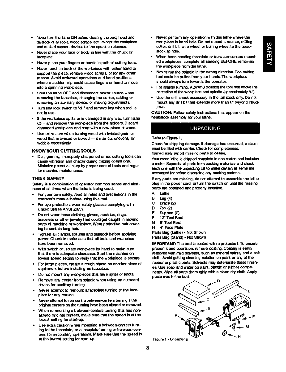
Refer to Figure 1.
Check for shippingdamage.If damage has occurred, a claim
mustbe filedwith carder.Check for completeness.
Immediatelyrepod:missingpartsto dealer.
Yourwoodlatheisshippedcompleteinone c_ton and includes
amotor.Separate allpads frompackingmaterialsandcheck
each one withthe unpaddnglistto makecertainall items are
accountedforbeforediscardingany packingmaterial.
If any parts am missing, do not attempt to assemble the lathe,
plugin the pawer cord,ortum the switchon untilthe missing
pads are chtained and properlyinstalled.
A lathe
B Leg (4)
C Brace(2)
D TSP(2)
E Support(2)
F 12" Teel Reef
G 6"ToolRest
H 4" Face Plate
Parts Bag (Lathe) - NOtShown
PartsBag (Stand)- Not Shown
IMPORTANT: The bed is coatedwith a protediant.To ensure
proper fitand operation,remove coating,Coatingis easily
removedwith mild solvents,such as mineralspirits, and a soft
doth.Avoidgettingcleaningsolution on paint or anyof the
rubberor plasticparts,Solventsmay deterioratethesefinish-
es. Use soap and water on paint, plasticor rubbercompo-
nents.Wipe all parts thoroughlywith a clean dry cloth.Apply
pastewax to the bed,
Rgum I -Unpacking
3
Page 4
Refer to Figu="es2 - 3.
CAUTION: Do not attempt assembly if parts ere missing.
Use this manual to order replacement parts.
• Remove all components from the shipping carton and verify
against the parts list on page 3. Clean each component and
remo_ shipping preservatives (coatings) as required.
ASSEMBLE STAND
NOTE: Hand tighten all I_ nuts duringstand assembly.Do
notcompletelytightennutsuntilstand assemblyis complete.
• Piecebcth toppiecesepside downee flooror benchtop.
Attach|font and rearsqoportsto topsusingtheca,'dagebolts,
flatwashers,lockwashersand hexnuts.
• Attach legs to inside nt tops usingcarriagebols, flat
washers, lockwashers and hex nuts,
• Attachbracesto insideof legsusingcarriagebolts,flatwash-
ers, lechwashersand hex nuts.
• Turnstand upright,level standandsecuresil nuts.
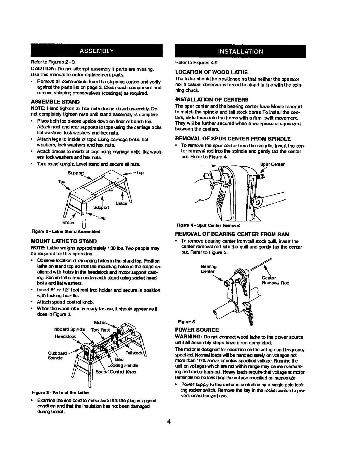
Suppo_
1\
Rgum 2 - Lalhe Stand Asmmbied
MOUNT LATHE TO STAND
NOTE: Latheweighs apprceimately130 Ibs.Two people mw
be requiredfor this operation,
• Obse_e Iocehend meentingholesin thestand top.Pceitinn
latheon stand topsothat the mountingholesinthe stand are
alignedwithhobs inthe headstock and n_tor suppodcast-
ing.Securelathefrom underneathstand usingsed_ head
boltsandflatwashe(s.
• Insert6" or 12" toolrest into holderand secure in position
with lockinghandle.
• Attach speed controlknQb.
• Whenthe woodlethe isreedj/foruse,it shouldappear as it
doesin Figure3,
Inboard Spinde Toel ReSt
Headstock
Spinde
Rgum 3 - Pmls of the Lathe
• Examine the liee cord to male ,,_Jrethel the ping is in geed
condition and that the insulation has not been damaged
during transit.
Bed
Halide
Knob
Reler to Figures 4-9,
LOCATION OF WOOD LATHE
The lathe shouldbe positionedsothat neither the operator
nor a casual observer isforced to stand in line with the spin-
ningchuck.
INSTALLATION OF CENTERS
The spur center and the bearing center have Morsetaper #1
tomatchthe spindleand tailstockbores.To install the cen-
ters,slide them intothe boreswith a firm,swift movement.
Theywill be furthersecured when a workpieceis squeezed
between the centers.
REMOVAL OF SPUR CENTER FROM SPINDLE
• To removethe spur centerfrom the spindle, insert the cen-
ter removalrod intothe spindle and gently tap the center
out.Refer to Figure4.
Spur Center
R_ure 4 - Spur Center RBmovzd
REMOVAL OF BEARING CENTER FROM RAM
• To remove bearing center from tall atock quill, insert the
center remavai rod into the quill and gently tap the center
out.Refer to Figure5.
Beanng
_r
Removal Rob
RRure 5
POWER SOURCE
WARNING: Do nat connectwood latheto the powersource
untilall assemplysteps have been completed,
The motorisdesignedforoperationontheveltageand IreqnenoJ
spedled.NotTnatloadswillbe handledsafelyan voltagesnot
morethan10% aboveorbelowspecifiedvolage. Ruanklgthe
un! onvoltageswhichare notwthin rangemaycauseoverheat-
n:j and motorburn-out.Heavyloadsrequirethatvoltageat mator
terminalsbe nolessthanIhevoltagespecified on namepla_.
• Powersupplyto the motoriscontrolledbya single polelock-
ingrod_r switch.Rerno_ the kayinthe rockerswitchto pre-
ventunauthorizeduse.
4
Page 5
GROUNDING INSTRUCTIONS
WARNING: Improper conr_dion d equipmed grounding con-
ductor can ras.J inthe dsk d electrical shod<.Eq_ment should
be grounded while in use to protect operstor from eleddcal shock.
• Check with a qualified elestdcian if grounding instructions
are not understood or i in doubt as to whether the tool is
propedy grounded.
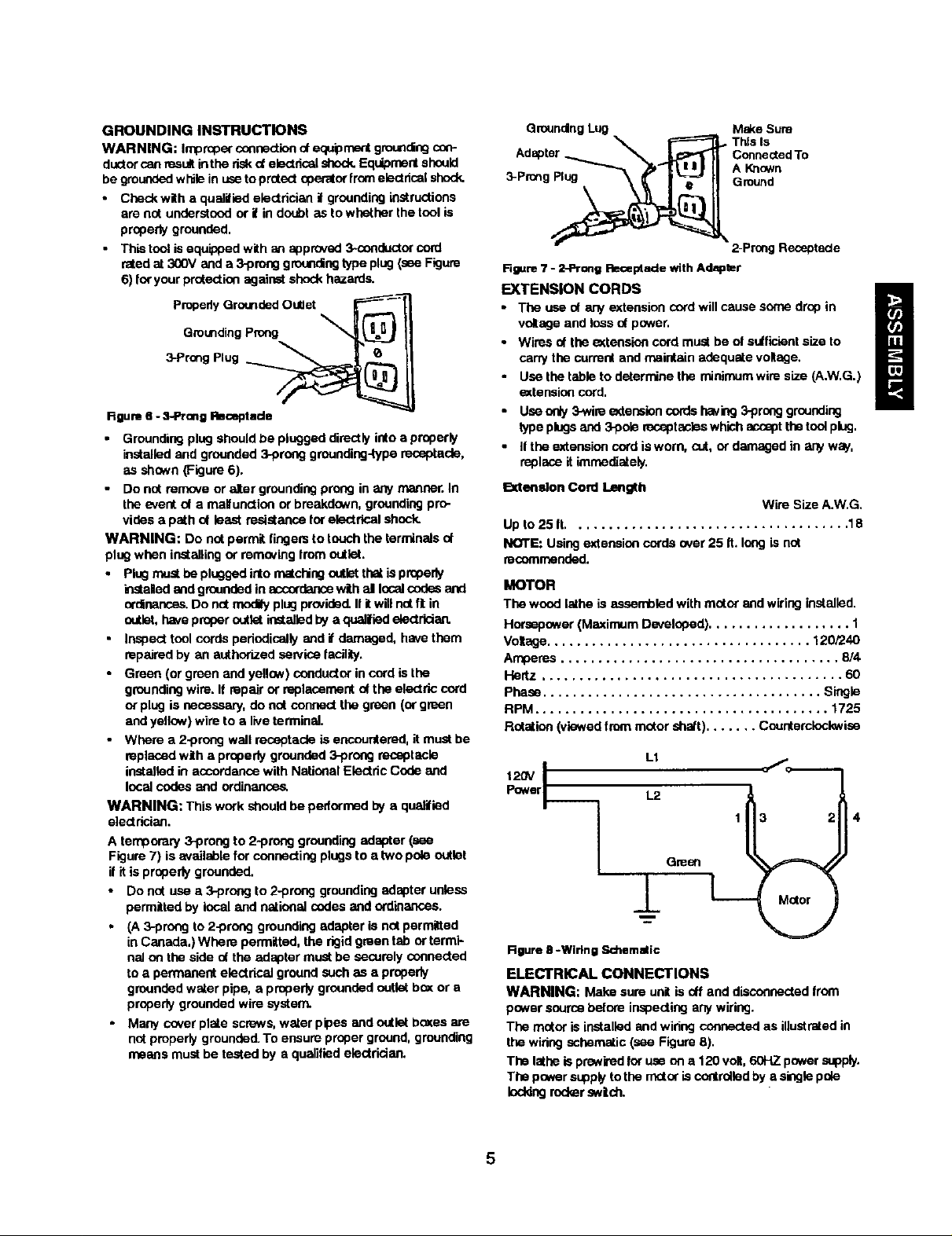
• This tool is equipped with as appmvad 3*conductor cord
rated at 300V and a 3-prong grounding type plug (see Figure
6) for your protection against shock hazards.
pmpedy Grounded Outlet
Grounding Prong
3-prong Plug __
Rgum 6 - 3-1ProngRmceptado
Groundingplugshouldbe plugged directlyinto a properly
installedand grounded3-preeg grounding-typereceptacle,
as shown (Figure6).
• Do not ran'x_e or alter groundingprong in anymanner.In
the eventot a maitunctionor breakdown,groundingpro-
vides a path ot least resistancefor electrical shock.
WARNING: Do notpermit lingers to touchthe terminalsot
plug when installingorremoving lrem outlet.
• Plugmustbe pluggedinto matchingoutistthatis propeby
instaled ond groundedin accordancewith al localcodasand
ordinances.Do notmodly plugprovided.If itwill nO[ft in
outlet,haveproperoutletinstalledby aqual|led electrician.
• Inspecttool cordspedodicellyand if damaged, have them
repairedby an authorizedseP.'iceIacitity.
• Green (orgreen and yellow)conductorin cord isthe
groundingwire.If repairor replacementof the electriccord
or plugis necessary, do not conned the green (orgreen
and yellow)wire to a liveterminal.
• Where a 2-prong wall receptacleisencountered,it mustbe
replacedwith a properlygrounded :)-prongreceptacle
installedin accordancewith National Electdc Code and
local codes and ordinances.
WARNING: This work should be pedormed by e qualified
electrician.
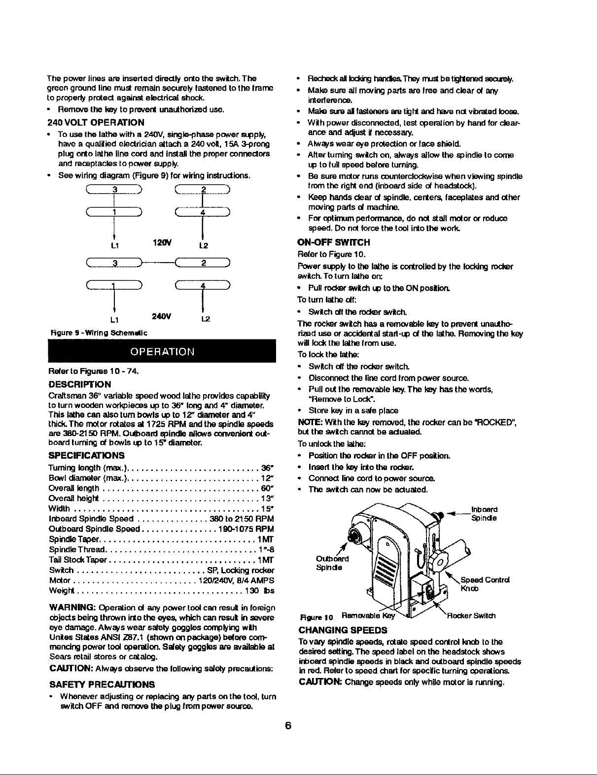
A temporary 3-preng to 2..prenggroundingadapter(see
Figure7) is availableforconsentingplugsto a two pole outlet
ifit isproperlygrounded.
Do notuse a 3-preng to2-preng groundingadaptor unless
permittedby localand national codas and ord'mances.
(A3-prongto 2-prong groundingadapter is not permitted
inCanada,) Where permitted,the rigidgreen tab or term'l-
natonthe side ot the adaptermust be securelyconnected
to a permanent electricalground such as a propedy
groundedwater pipe, a properlygroundedoutlet b_( or a
properlygroundedwire system.
• Many coverplate screws,water pipes and outletbosasare
notproperlygrounded.Toensure proper ground,grounding
means mustbe testedby a qualifiedeleotrician,
Qmunding Lug M_<e Sum
Adspter_ __ConnectedTo
3-Prong Ground
_A Kqown
Rgure 7 - 2-Prong Receptacle with Adapter
EXTENSION CORDS
• The use of any extension cord will cause some drop in
volnge and loss of power.
• Wires of the _tension cord must be ol sutficisnt size to
carry the ourmnt and maintain adequate voltage,
• Use the table to determine the minimum wire size (A.W.G.)
extension cord.
• Use only 3-wire eadenslen cords h_iug 3-prong grounding
type plugs and 3-pob mceptasles which accept the tool plug.
• If the extension cord is worn, cut, or damaged in any way.
replace it immediately.
Extemdon Cord length
Up to 25 tt..................................... 18
NOTE: Using extension cords over 25 It, long is not
recommended.
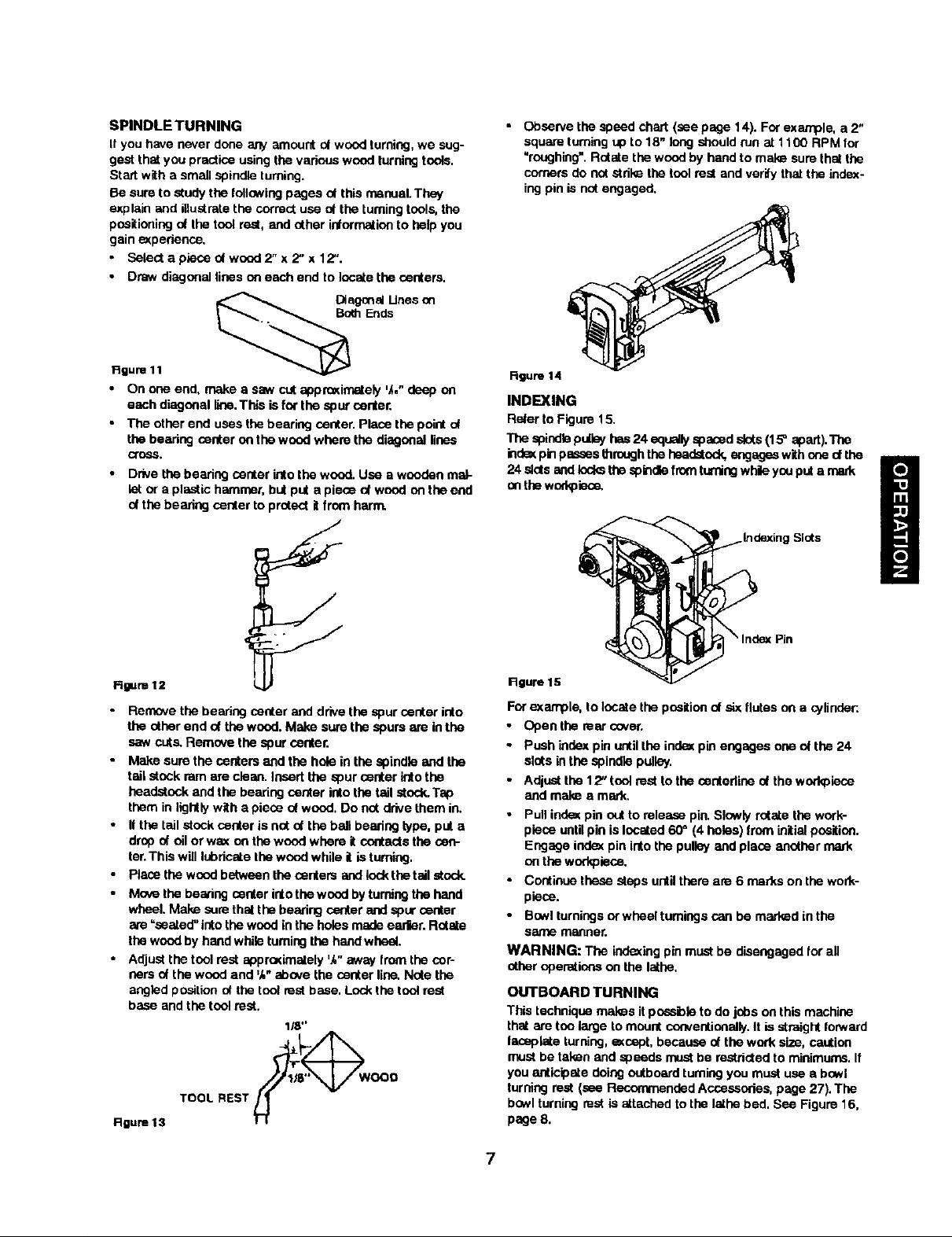
MOTOR
The wood lathe is assembled with rector and wiring installed.
Horsepower (Maximum Developed) ................... 1
Voltage ................................... 120/240
Amperes ..................................... 814
Hertz ........................................ 60
Phase ..................................... Single
RPM ....................................... 1725
Rotation (viewed Iron', mater shatt) ....... Counterclockwise
L1
120V IPower L2
1
Green
This Is
2-Prong Receptacle
Wire Size A.W.G.
±
Rgure B -Wiling Schemstic
ELECTRICAL CONNECTIONS
WARNING: Make sureunit isoff anddisconnectedfrom
powersourcebesominspectingany wiring.
The motor is installedand wiringconnectedas illustratedin
the widngschematic(see Figure8).
The lathe isprewiredlot useon a 120volt,60HZ powersupply.
The powerst4)plytothe motoris controlledby a singlepole
leddng roder swich.
5
Page 6
The power lines are inserteddirectly ontothe switch.The
0teen groundline must remain securelyfastenedto the freme
to properlyprotect againstelectricalshock.
• Removethe key to preventunauthorizeduse.
240 VOLT OPERATION
• To use the lathe with a 240V, single-phase pov,,er supply,
have s qualified electrician attach a 240 volt. 15A 3-prong
plug Onto lathe line cord and install the proper connectors
and receptacles to power supply.
• See wiring diagram (Figure 9) for wiring instructions.
C 3 C 2
__L_
C 4 )
L1 1_ _
_ 2 )
L1 240V 1.2
Figure 9 -Wiring S<d'lemallc
Referto Figures10 - 74.
DESCRIPTION
Craftsman 36" variable speed wood lathe providescapability
toturnwoodenworkpieces upto 36' longand 4" diameter.
This lathe can also turn b_wls up to 12" diameterand 4"
thick.The motorrofstosat 1725 RPM and the spindle speeds
are 380-2150 RPM. Outboard spindle allows convenientout-
boardturningof bowls up to 15" diameter.
SPECIFICATIONS
Turninglength (max.) ............................ 38"
Bowldiareeter(max.)............................12"
Overalllength................................. 60_
Overallheight................................. 13"
Width ....................................... 15"
Inboard SpindleSpeed ............... 380 to 2150 RPM
OutboardSpindle Speed ................ 190-1075 RPM
SpindleTaper................................. 1MT
SpindleThreed ................................ 1".-8
TailStock Taper............................... 1MT
Switch ........................... SP, Lockingrocker
Motor .......................... 120/240V, 8/4 AMPS
Weight ................................... 130 bs
WARNING: Operationof any powertoolcan result in foreign
objects being thrown intothe eyes, whichcan result in severe
eye damage. Alwayswear satety gogglescomplyingwith
UnitesStatesANSI Z87.1 (shown onpaskage) before com-
mencingpower tooloperation.Salaty goggles ate available at
Sears retail storesor catalog.
CAUTION: Always Observethe followingsafelyprecautions:
SAFETY PRECAUTIONS
• Whenever adjustingor replacinganyparts onthe tool, turn
switchOFF and removetheplug from power source,
• FlesheckallIoddnghandles,Thaymustbe tightensdseoJraly.
• Mak_ sure allmovingparts are free and clear of any
intederence.
• Mal® s_.a'eal fastonarsam tightand have nctvbratedloose.
• With power disconnected,testeperetion by handforclear-
ance and adjustit necessary.
• Always wear eye protectionorface shield.
• Alter turningswitchon, alwaysallow the spindle to come
upto lull speed before turning.
• Be suremeter runscounterclockwisewhen viewing spindle
fromthe rightend (inboardside of headstock).
• Keep handsclear of spindle,centers, faceplates and other
reeving parts of machine.
• For optimum performance,do not stall motoror reduce
speed. Do not forcethe toolinto the work.
ON-OFF SWITCH
Refer to Figure 19.
Power supplyto the lathe iscontrolledby the lockingrocker
switch.To turn latheon:
• Pullred_r snitchupto the ON position.
Toturn lathe _f:
• Switchoff the rockersNitCh.
The rocker switch hase removable_ to preventunsetho-
dzBd use or accidentalstart-up of the lathe.Removingthe kay
will !ock the lathefrom use.
To lock the lathe:
• Switchoffthe rockerswitch.
• Disconnectthe line cordlram powersource.
• Pullout the removablekey.The key has the words,
"Remove to Lock".
• Store key in a sale pla_e
NOTE: With the kay removed,the rockercan be "ROCKED",
butthe switchcannot be actuated,
Tounlockthe Isthe:
• Positionthe rockerin the OFF pneltinn.
• Insertthe key into the rocker,
• Connect line cord to power source.
• The switch cannow be actuated.
• _ Spindle
Rgum 10 RemovableI_ _/ _Roc_erSwltch
CHANGING SPEEDS
Tovaly spindlespeeds, rotatespeed controlImopto the
desiredsetting.The speed label on the headstock shows
inboardspindlespeeds in blackand outboardspindle speeds
in red. Refer tospeed chartfar specific turningoperations.
CAUTION: Changespeeds only while motor is running.
6
Page 7
SPINDLE TURNING
If you have never done any amountot wood turning,we sug-
gestthatyou practiceusing the variouswood turningtools.
Start witha small spindleturning.
Be sureto studythe follo_vingpages ofthis manuel.They
explainand illustratethe correctuse at the turning tools,the
positioningot the tool rest, and other informationto help you
gaine_pedence.
• Select a plese ot wood 2" x 2" x 12".
• Draw diagonallines on each end to locatethe centers.
Diagonal Unes on
Both Ends
• Observe the speed chart (see page 14). For example, a 2"
square turning uP to 18" long should run at 1100 RPM for
"roughing'. Rotate the wood by hand to make sum that the
corners do not strike tim tool rest and verify that the index-
ing pin is not engaged.
Rgure 11
• On one end, make a saw cut epprosJn'_ely 'A," deep on
each diagonal line,This isfor the spor o_nter,
• The other end uses the bearing center. Place the point ot
the bearing center on the wood where the diagonal lines
cross`
• Drivethe bearingcenter intothe wood.Use a wooden mat-
let or a plastichammer, butput a piece of wood onthe end
ofthe bearing centerto prctect itfrom harm.
Rgum 12
• Remove the bearing center and drivethe spur center into
the otherend of the wood. Make sumthe spurs are inthe
saw cuts. Remove the spur center.
• Make surethe centersand the hole in thespindle and the
tailstock ramare clean. Insert the spurcenter intothe
headstock and the bearing center intothe tail atock.Tsp
them in lightlywith apiece ot wood. Do not drivethem in.
• II the tall stock centeris not ot the ball bearingtype, puta
dropof oil or wax an thewood where itcontactsthe cen-
ter.This willIt_,ricatethe woodwhile it is tumiag.
• Placethe woodbetween the centers andlockthe t6il stock.
• Movethe bearing centerintothe woodbyturningthehand
wheel.Make surethatthe bearingcenterand spur center
=seated"into thewood inthe holesmadeeadier.Rotate
the woodby handwhileturningthe handwheel.
• Adjustthe toolrest approximately',_"away fromthe cor-
nersof the wood and %"shove the centerline. Note the
angledpositionof the tool restbase. Lockthe tool rest
base and the tool rest.
1_ _'
,oo°
Rgure 13
TOOL REST _._
Rgure 14
INDEXING
Referto Figume15,
The spinulepu[k3yhas24 agu_Jlyspaced slots(15° apart).The
irides(pin psssesthroughthe headstockengageswithonect the
24 slotsemdlocksthespindle fromturningwhileyouputamark
on thewod_lec_
iSlots
Rgure lS
Forexample, to locatethe positionot sixflutes on a cylinder:.
• Openthe rearcaver.
• Push indexpin untilthe indexpin engages one ef the 24
slats inthe spindle pulley.
• Adjustthe 12" toolmeatto the centerlineot the workplece
and make e mark.
• Pullindexpin outtorelease pin,Slowly rotate the work-
piece untilpin is located 60" (4 holes) from initial position.
Engage index pin into the pulleyand place another mark
on the workpiece.
• Continuethese stepsuntilthere are 6 marks onthe work-
piece.
• Bowlturningsor wheel turningscan be marked inthe
S_ rn_qReL
WARNING: The indexingpinmustbe disengagedfor all
nther operations on the lathe,
OUTBOARD TURNING
This technique mat_s it possible to do jobs on this machine
that are too large to mount conventionally. It is straight forward
laospiste turning, except, because of the work size, caution
must be talon and speeds must be restricted to minimums. If
you anticipate doing outboard turning you must use a bowl
turning rest (see Recommended Accessories, page 27). The
bowl turning rest is attached to the lathe bed. See Figure 16,
page 8.
7
Page 8
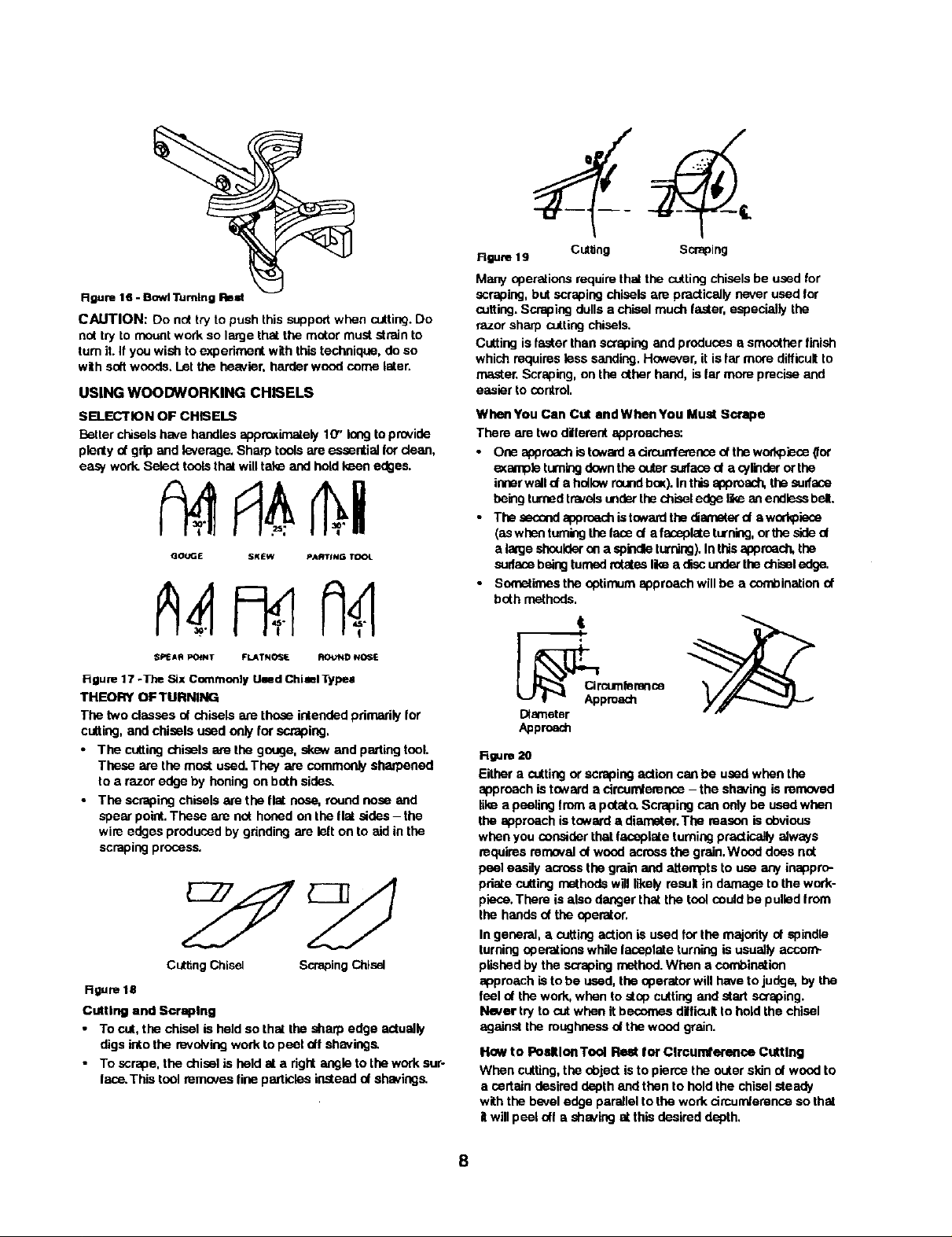
figure 16 - Bowl Turning Rest
CAUTION: Do not try to push this support when cutting.Do
nottry to mountwork so large that the motor must strain to
turnit. If youwish toexperimentwith thistechnique,do so
with softwoods.Let the heavier, herder wood come later.
USING WOODWORKING CHISELS
SELECTION OF CHISELS
Betterchiselshave handles approximately10" longtoprovide
plentynt gripand leverage.Sharptoolsare essentialIordean,
easywork.Selecttoolsthatwilltake and hold keen edges.
GOUGE SKEW PA_TfNG T_04_
SPEA fl POINT FLATNOSE ROUND NOSE
Figure| 7-The Six CommonlyUsedChimlTypes
THEORY OF TURNING
The two classes ot chisels are those intendedpdmadlyIor
cutting,and chisels used only forscraping,
• The cuttingchisels are the gouge, skew and partingtool.
These are the mostused.They are commonlysharpened
to a razor edge by honingon both sides.
• The scrapingchiselsare the flat n_e, roundnose and
spear point.These are not honedon the flat sides- the
wire edgesproducedby grindingare felt on to aid in the
scrapingprocess.
Cutting Chisel Scraping Chisel
Rgum 18
Cutting and Scraping
• To cut, the chisel is held so that the sharp edge actually
digs into the revolving work to peel otf shavings.
• To scrape, the chisel is held at a dgN angle to the work sur-
lace. This tool remcves fine particles instead of shavings.
Rgure19 Cuttin S "
Many operationsrequirethat the cuttingchiselsbe used for
scraping,but scraping chiselsare practicallynever used for
cutting.Scrapingdullsa chiselmuch faster, especiallythe
razorsharp cuttingchisels.
Cuttingisfaster than scrapingandproduces a smootherfinish
whichrequiresless sanding.However, it isfar more difficultto
master.Scraping, on the other hand, is lar moreprecise and
easier to control.
WhenYou Can Cut andWhanYou Must Scrape
There are twoditlemnt approaches:
• One sppr_ch istowardedrcunfemsce oftheworkpiece_or
exampleturningdowntheoutersurfaced a cylinderor the
innerwalld a hollowroundbex).In thisapproach,thesulfase
hek'igturnedtravelsunderthechisel edgelikean endlessbelt.
• The secondapproachistowardthe diameterd a workpiece
(aswhen turningtheface d afsceplate turning,or the sided
a largeshoulderon a spindleturning).In thisapproach,the
sudscebeingturnedrotatesIke a discunderthechisel edge.
• Sometimesthe optirnum approachwill be a sent)ination of
both methods.
t
Diameter
Approach
Rgum 20
Eithera cuttingor scrapingaction canbe used when the
approachis towarda circumference- the shavingis mmaved
like a peelingfrom a potato.Scraping can only be usedwhen
the approachistowarda diameter.The mason is obvious
whenyou considerthatfaceplate turningpracticallyalways
requires removalof woodacross the grain,Wood does not
peel easily acrossthe grain and attemptsto use any inappro-
pdate cuttingmethodswilllikelymsul in damage tothe work-
piece.There isalso danger thatthe tool couldbe pulledfrom
the hands of the operator.
In general, a cueing actionis used for the majorityof spindle
turningoperations while taceplateturning is usuallyaccom-
plishedby the scrapingmethod.When a combination
approach isto be used, the operator will haveto judge, by the
feel ot the work,when tostopcutting and start scraping.
Never try to cutwhen itbecomes difficultto holdthe chisel
againstthe mughnese ofthe wood grain.
Haw to PosltlonTool Rest for Clrcurnterenoa Cutting
When cutting,the object isto piercethe outer skinof woodto
a certain desireddepthand thento hold the chiselsteady
with the bevel edge parallelto the work cimundemnceso that
itwillpeel oft ashaving at this desired depth,
8
Page 9
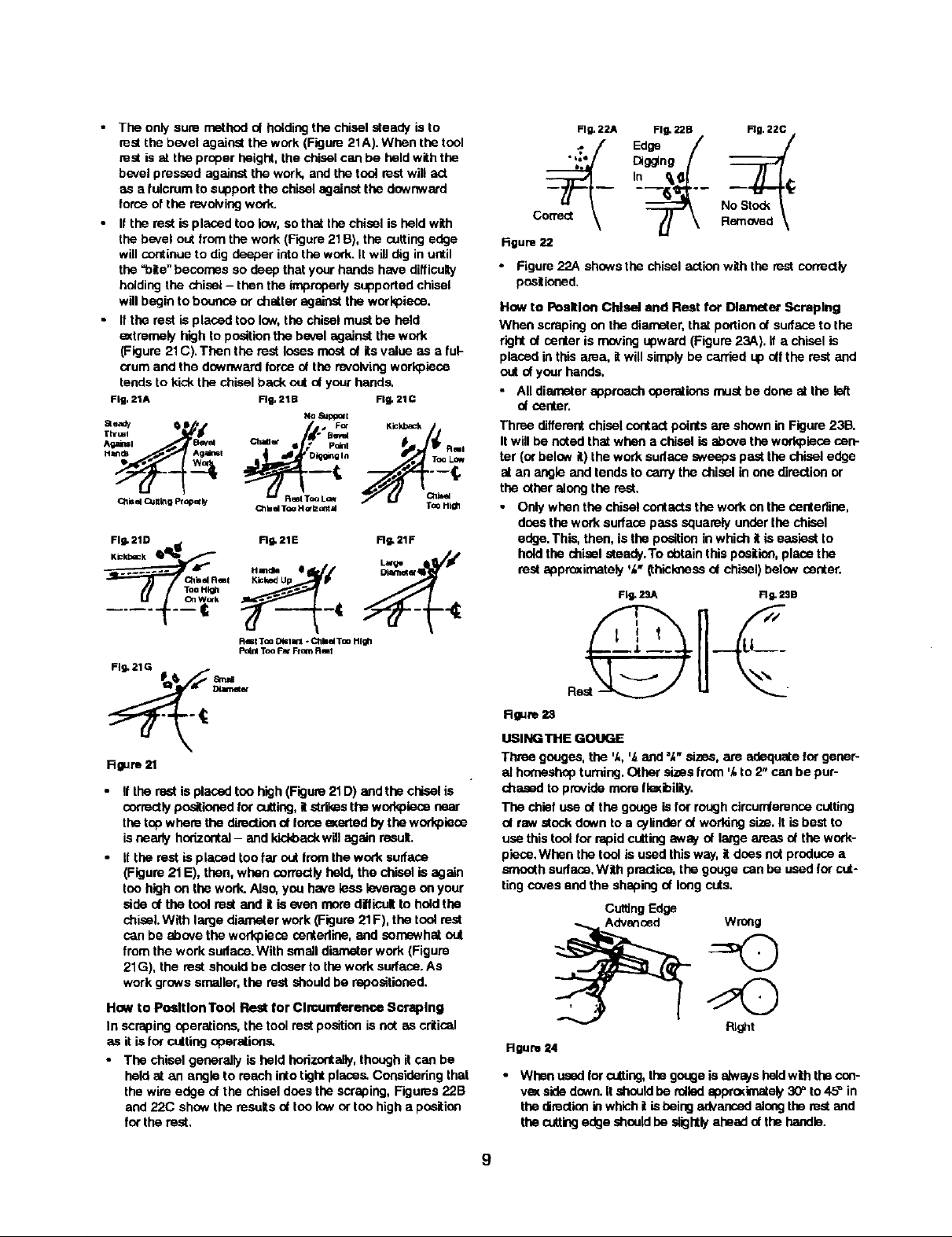
• The only sure methodof holdingthe chisel steady is to
mat the b_velagainst the work(Figure 21A).When the toni
mat is at the proper height, the chiselcan be held withthe
bevelpressed againstthe work, and the tool restwill act
as afulcrum to support the chisel againstthe downward
forceofthe revolvingwork.
• If the rest is placed too low,so that thechisel isheld with
the bevel out from the work (Figure21B), the cuttingedge
will continueto dig deeper intothe work.It will dig inuntil
the "bite" becomes so deep that your hands have difficuly
holdingthe chisel- then the improperlysupportedchisel
will beginto bounce or chatter against the workplace.
• ffthe rest is placed ton low,the chisel mustbe held
extremely high to positionthe bevel against the work
(Figure 21C).Then the rest losesrno_ of itsvalue as a ful-
crumand the downwardforce ofthe revolvingworkplecu
tends tokickthe chiselback out of yourhands.
Fig. 21A Rg, 21B Rg. 21C
ae_ _ S • . F_ Kickback/i
Xhr=, '_ Chan /d" Bev_ Kickba=_.
^_ml B_ _ • [ pelnl
Ctlisel (_jn_g pl_er _ _ R_I Too L
Fig. 21D I_ Fig, 21E RI_ 21F
..... _I_R_ I Handle e
TooHi_
Olbd TOU H G'lz_m d TOO Itl_h
No aJp_xt
Fig, 22A
• ioe
c
figure 22
• Figure 22A showsthe chiselactionwith the rest correctly
positioned.
How to PoalUon Chisel and Rest for Diameter Scraping
When scraping on the diameter, that portico of sudase tothe
right of center is moving upward (Figure 23A). if a chisel is
placed in this area, it will simply be carrisd up oft the rest and
out of your hands.
• All diameter approach aparations must be done st the k_t
of center,
Three differentchiselcontactpoints are shownin Figure 23B.
Itwill be notedthatwhen a chisel is abovethe workpieoscen-
ter (or belowit) the work sudase sweeps pastthe chisel edge
at an angle and tendsto carry the chisel in one directionor
the otheralongthe rest.
• Onlywhenthe chisel centasts the work on the cehtedine,
doesthework surfacepass squarelyunderthe chisel
edge.This, then, is the positioninwhich it is easiest to
holdthe chiselsteady.To abtain thisposition,placethe
restagpreximataly 'k" (thicknessof chisel)balsw center.
Fill- 2SA FI w. 23B
Rest Too D_IW31 * ChbalToo High
P_nl Too Fat From Rmt
Fig. 21G
Rgure 21
Ifthe restis placedton high (Figure21D) and the chisel is
correctlyposlioned tar cutting,itstdkes the workplecunear
the top where the directionof torceeKartedbytheworkplace
isnearly horizontal- and kickbackwillagain result.
• Ifthe rest isplaced too far out Iromthe work surface
(Figure21E), then, when correctlyheld, the chisel is again
tonhighon the work.Also, you hawetessleverage on your
side of the tool restand it is even more difficultto hold the
chisel.With largediameter work(Figure21F), the tool rest
canbe abovethe workplece centedine,and sornewhal out
from thework sudace,With small diameterwork (Figure
21G), the restshouldbe closerto thework surface.As
workgrows smaller,the restshouldbe mpositioned.
How to Po_ltlon Tool Rest for Clmunfference Soraplng
In scrapingoperations,the tool restpositionis not as critical
as it isfor cuttingoperations.
• The chisel generally is held horizontally,though itcan be
held at an angle to reach intotightplaces,Considering that
the wire edge ofthe chisel does the scraping,Figures 22B
and 22(3 showthe resultsof ton low or ton high a position
forthe rest.
Uw_
R
Rgum 23
UISING THE GOUGE
Three gouges, the 'k,',_and =k"sizes, are adequateforgener-
al hornesheptumieg, Other sizes from 'k to 2" can be pur-
chased to provide more IleKibinty.
The chief use ofthe gouge is for roughcircumfarenoscutting
ofraw stock down to a cylinderofworfdngsize.It is best to
usethis toolfor rapidcuttingaway of large areas of the work-
piece.When the tool is used thisway, it doesnot producea
smoothsudace,With practice,the gougecan be usedforcut-
tingcovesand the shapingof longcats.
CuttingEdge
P_fflt
Hgum 24
• When ussdfor o-tting,thegougeisalwaysheldwiththecon-
veKsidedown.It should he rolledapprodmatel),30=to 45_ in
thedirectioninwhich| is beingadvancedalongthe restand
thecuttingedge shouldhe slightlyaheadct thehandle.
9
Page 10

USING THE SKEW
• Two skews, the '/z and 1" sizes, am all that are needed for
general use. Other sizes are avallsble,
This tool isnearly always used to ma_ fbished cuts, to cutvees
and beads, and to square shoulders. Properly used, i produces
the best finish that can he obtained with a chisel. It is not recom-
mended forscraping because the edge tends to dul more qalddy.
For finish cutting, the skew is held with the cutting edge
considerably in advance of the handle, bevel side down.
Keep the base ol the bevel against the work. It is good
practice is to place the skew well o_,er the wod_, pull it back
until the edge begins to cut, then owing the handle into
position to advance the cut.
Both the toe and the heal d the slew can be used fortaking light
cuts, but do not penetrate the wood too deeply without cutting
_s.There is danger ol burring the tip of the tooL
Rgure25
USING THE PARTING TOOL
The pwting tool has just one prrnaw purpose: to cutinto the
workpiece as deeply as desired, or all the way through to make a
aJt-off, It is,the_ore, a very narrow tool ak" wide) and shaped to
cut its own clearance so that the edge will not he burned.When
used for scraping, however, the parting tool should be backed off
regularly to prevent overheating.
Unli_ the gouge and slew, the parting tool is seldom hatd with
the beval against the work. Since the _nt of stock removal is
small, a support for the bevel is not neoes_y.
The tool is simply led into the work at an angle (for cutting), or
pointed at the workpleoe center (Ior scraping). It can be held eas-
ily in one hand.
Cutting Scraping
4--,,
USINGTHE SCRAPING CHISELS
• A '/l' wide spear point chisel, a '/z"wide round nose chisel,
and a 1" wide flat nose chisel complete the list of tools
ordinarily used by crattsmen and hobbyists.
Each of these scraping chisels can be purchased in various
other sizes Ior special purposes. All am very useful for diame-
ter scraping operations and for circumference scraping when
cutting methods cannot be employed.
• The spear point is used for line soraping and delicate oper-
ations such as the forming of beads, parallel grooves and
shallow vses.
• Edges and bowl contours can be rounded with the round
nose chisel.
• Any flat sudaca can be scraped withthe flat nose chisel.
Spear Round Flat nose
Point Nose
figure 27
USING SHAPER OR MOULDING KNIVES
• An old chisel can be made to serve as a holder for shaper
or moulding knives.
Such knives male it possible to scrape many interesting
shades into the workpiece surface using _ or two operations
instead of the many operations required wih standard chisels.
it is generally not practical to use cutting mathods with spedal
shape tools. Scraping methods should he used instead.
• The holder should provide a shoulder against which the
butt end of lhe krlite can be firmly seated,The knife must
be securely mounted, either by means nt a screw threaded
into the holder, or by compressing it between two prongs
bolted together.
USING A BLOCK PLANE
Clear, glass.smooth linishes (especially on softwoods) can be
obtained by using a block plane sat to take a fine shaving.
• The tool rest should be raised up apprasimately to the top
of the workplece - and the plane should be horizontal, but
turned slightly in the direction of travel so that it will tale a
shearing cut,
• Two tool rests, one in front and the other behind the work, can
be used to advantage in p_itioning the plane so as to eKaotly
limit the dep(h ofcut (and fi_ size of the wod_piece).
Rgum 2g
USING WOOD RASPS AND FILES
• A wood rasp will remove stock quickly when held against
the revolving workpisce. Cam should be talen to support
the rasp firmly against the tool rest. An improperly held
rasp, when used on a rough sudaoe, can kick back and
cause operalor injury,
• The rasp will leave avery rough finish.
• Finer finishes (similar to those produced by scraping) can
be obtained by using files in the same manner. Various
types of files can be used for shaping vees, beads, caves,
eLc. if pressed too hard into the wood, some files can burn
the workpiece.
• Keep the file clean to keep it cutting uniformly. Files work
best on hardwoods.
10
Page 11

Figure 3Q - Using a Rup
HAND POSITIONS
When usinganyofthe chisels,thehandtales a naturalposition
on thetoniheedl_This pssitionmavbe nearthe middled the
handleor towardsthe end,dependingupanthe amesntof
leveragerequired.The positisnd theI'_nd neartheted re.stis a
matterd individualprdemnee,bUttheream threegenerally
acceptedpositions,each bestforcertaintypesd operations
Roughing Off
Roughingofl and other heavy work requires a firm gripand
solidpositioningof the chiselagainstthe rest.This is best
obtainedby the toet-mat hand positionedillustrated.The wrist
is droppeddownso that the heel of the handbelowthe little
finger acts as a slidingguide against the rest,The handle
hand controlschiselposition.
Rgure 31 - Roughing
Finish Cutting
Finishcuttingrequires more control- with less force.Finish
cUttingis betterdone withthe palm of the toolrest hand
turned up.The wristis stillheld down, and the side ot the
indexfinger acts as a guide along the rest. In thispselico,
controlof the chiselis sharedby both hande.The lingersof
the teet-reet hand are free to assistin positioningthe tooL
Figure 32 - Finilh Cutting
Intdeete Cutting
intricate,delicate cuttingrequireseKtremecontrolwithpracti-
callyno force.This is best accomplishedby guidingthe chisel
withthe fingers of the tool-resthand.The hand is held palm up
withthe wristhigh.The littlefinger isplaced againstthe restto
steady the hand.The chiseldoesnottouchthe restandthe
handlehand iscompletelysecondaryto the tooFresthand.
NOTE: The firstand secondpositionsare equallygoodfor
scrapingoperations,hot the thirdpositionispracticallynever
usedfor scraping.
Rgure 33
Cutting to Depth
Many scraping operations and cUtting to depth with the part-
ing tool can be easily accomplished with the one hand. The
chisel is grasped firmly with the index finger on top to press it
down against the rest. it is thrust straight into the work.
Holding the tool in this manner leaves the other hand free to
hold a p_tem or calipers, atc., to check work in progress.
%..
Rgure 84
MAKING STANDARD CUTS
THE ROUGHING-OFF CUT
Reducing a square or odd shaped workDieos down to a cylin-
der of approximate size for finish turning is called "roughing-
off". Faosplste turnings and large diameter spindles should
first be partly reduced by sawing, but small spindles are easily
turned down entirely with the large (',_') gouge.
RO_o
• Start the firstcutabout 2" from tail stock end - then runit
towardthe tailatnekand off the end of theworkpieos.
• Nsst, startanothercut 2" nearerthe headstock- and run it
back towardsthetaiistnek,to mergewith the firstcUt.
• Continuecuttingin this manner until2 to4" from the head-
stock is lett uncut.Reverse the directionof tooltraveland
workone or twocUtsin successiontowardthe headstock
and(_f thisend of the workpieee.
• Never start a cUtdirectlyst the end - if the chisel catches
the end, it willdamage the wod_leco.
• Never take longcutswhile cornersremain onthe work,as
this tends to tear longdivers fromthe corners,
• The first series of cuts shouldnot tie ton deep. It is better
topartiallyreduce the workto a cylinderall along its
length.Afterthat, start a second series of cutsto complete
reducingitto a cylinder.
* Once a cylinder has been Iormed,step lathe up to next
fasterspeed. Furtherreductionsin size can now he
accomplishedbycuttingas deeply as desired at any spot
along thework.Atthis stage, longcuts can be madefrom
the centerto eitherend.
• Generally,roughingoff is continueduntilthe cylinder is
approKimately %"lan:jerthan the desired finished size.
11
Page 12

• Roundness can be tested by laying the gouge on top of
the work - it will not ride up and down when cylinder is
perfectly found.
Flrst Cuts
Testing Roundness
Figure 36
ROUGH-CUTTING TO SIZE
The roughing-ooIcut can be made to accuratelysize the cylin-
der to a given diareeter.
Anothermethod is to make a numberof sizing cuts at inter-
vals alongthe work, then use the gouge toreduce the whole
cylinderdown tothe diameterindicatedby these cuts.
MAKING SIZING CUTS
Sizingcutsam useJulto establishagprexim_e finishedsize
diametersat variouspointsalong a workpieos.The workcan
thenbe turned downto the diametersindicatedand be ready •
for finishing.
Diametersfor sizing cuts shouldbe planned to be about ',_"
greater than the desired finishdiameters.A sizingcutis
made withthe partingtoot,
• HoOdthe toolin one hand, and use the other hand to hoOd •
an outsidecaliper presetto the desiredsizing-cutdiameter.
• As the cut nears completion,lowerthe chisel point more
and more into a scraping pnettion.
• When the calipersslip overthe workoieseat the bottom oO
the groove,then the cut is linished.
Figure 38
• Use the gouge to remove any waste stock outside of shoul-
der. Smooth this section, up to within ',_"oOshoulder, in the
usual manner. Finishing at the shoulder, unless it is more
than 1" high, is best done with the q,_"sl_w.
The toe of the skaw is used to rem_x,e the shavings from
the side of the shoulder - down to finished size.
Hold skewsothe bottom edge of bevel neKtto the shoul-
der willbe vely nearlyparallelto side oOshoulder- but
with cuttingedgeturned away at the top so that only the
extremB toe willdo the cutting.If cuttingedge is flat
againstshoulder,the chisel will run.
Startwith handle low,and raise handleto advancetoe into
the work.
Cut down to finished diameter of outside area. Then, clean
out the corner by advancing heel of the skBw into it along
the surface of the outside area.
Tilt the cuttingedge, with handleraised up so that onlythe
extrsme heel does this cutting.
II shoulderis at end of work, the process is called aguadng
the end. In thiscase, mduse outerportionto a diameter
about '_" largerthan toolcenterdiaree_acThen,later, saw
off the waste stock.
Figure 37
SMOOTHING A CYLINDER
The final ',_"can be removed intwo ways,Either use the 1"
skaw,workingfrom the center towardbothends and taking
lighterand lightercuts until finished,or use a blockplane as
illustratedin Figure 29.
CUI"rlNG A SHOULDER
A shouldercanbe the side of a squareportion left inthe
workpisce,the side of a tarriedsection,or the end of the
workpisce.Most shouldersare perpendicularto thework axis,
but a shouldercan be at any angle.
• First, rnarkpositionof the shoulderwith a pencilheld to
the revolvingworkpieoe.
• Second, make a sizingcutwith the partingtool,placing
thiscut about '/,." outsidethe shoulderpositionand cutting
towithinabout '/," of the depthdesired for the area outside
at the shoulder.
• If shoulder isshallow, the toe of the skewcan be used to
make the sizing cut.Do not go in doeperthon',_"withthe
si_w unlesswider and wider vees are cutto provide clear-
ance for this tool.
Rgure39
CUTTING VEES
Vee groovescan be cut witheitherthetoe or heel of the skew.
• When the toe is used,the cuttingactionis exactlythe
same aswhen trimminga shoulderaxsspt that the skew is
tiltedto cut at the requiredbevel. Lightcuts shouldbe
takenon firstone side and then the other,gradually
enlargingthe vee tothe required depth andwidth.
• When the heel is used, the skmNis rotated down intothe
work, usingthe restas a pivot.Otherwise,cuttingposition
and sequence ot cutsam the same. As whenusingthe
toe, it is importantthat cuttingbe doneonly by extreme
end of cuttingedge.
• If deep vees are planned, it is quickerto start themby
maldngasizingcut at the centerof each vee.
• Voes can alsobe scrapedwith the spear point chisel or a
three-sidedfile.
12
Page 13

Roure 40
CUTTING BEADS
This operationrequiresconsiderablepractice.
• First, make a pencilline to locatethe tops (highestpoints)
of two or more adjoiningbeads,
• Then, male a yea greave st the axact centerbetweentwo
linesanddowntothe desired depth d the separation
betweenthe beads.Be carefulnotto make the groeveton
wide oryou willremovepodionsof the desiredbeads.The
sidesolthe two adjoiningbeads are now cutwiththe heeld
thesksw.Use a %"skew,unlessbeadsam veryla,'ge.
Placeskew st rightangleswiththeworkaxis,flatagainstthe
sudase,andwellup near the top.The axtrerne heelshould
be justit_sidethe pencillinethatmarksthe topof the bead.
Now, draw slew straightback whiio raisinghandle slowly-
untiledge nt the heel at the pencil linestartsto cut,
• As edge begins to cut, roll sl_w inthe directionol the vee
so thatthe _act portion of the edge which started cutting
willtravel in a 90" arc downto bottom of the vea.
Upenreachingbottomd thevee,the slew shouldbe en adge.
Reversethe movementsto cutside ol theadjacent bead.
_S_ng Tod
Rgure 41 - Cutting Beads
It is important that only the _treme heel should do the cut-
tiag.This means that the bottom edge nt the bevel naxt tothe
vea must at all times be tangent to the arc nt the bead being
lormed.
Easier beads can be shapedwith the spear pointchisel.
• Use pencilmarks and sizingcuts as belore.
• Push the chisel straightinto each cut end rotate horizontal-
ly to roundoff the adjacent edges. It mustbe moved slight-
lyin the directionof rotationat the same time to keep the
pointfromdiggingintothe adjacent bead.
• At the start of either cut, gouge is held with handle high
and the two sides of blade held between the thumb end
fore_ingar of tool rest hand, just behind the bevel.
Position the fingers so that they are ready to roll the blade
into cove.
* Holdbladessothstbevel is at 90° angletothe workaxis
withpointtouchingthe pencillineandpointedk'itowork a_is.
• Fromthis start, depresspoint slightlyto stad cut, thencoo,
tldueto movepoint down in an arc towardthe bottomcen-
ter cove - at the same time roilingchiseluniformlyso that,
at the end ol the cut, it willbe flat at the bottomof the
cove.The objectis to keep the axtrerne point of gouge
doingthe cuttingfrom start tofinish. Reversethese move-
mentsto cutthe opposite side.
_R_t CUttingCoves
Rgure 43
Coves alsocan be scrapedto finishusingthe roundnose
chisel or a rattailfile.These methodsdo nutgenerallypro-
duceperfectlycurvedcoves.
MAKING LONG CONVEX CUTS
•Firat, turn work downto eppraximate size, using sizingcuts
(as required)to determinevariousdiameters` Finishcuts
can then be madewith either skewor gouge.
• Ifthe slew is used, the pdncipiosof the operatlen are the
same asthose employedin cuttinga bead - exceptthat
the curveis leager and maybe irregular.Use the eKtreme
heel throughout- startat longerend of curve (if curve is
irregular)and progresstowardsteeper end.
• If gouge is used, make cut in the same direction.Start with
the handle well back of point- swinginghandle inthe
directiondi tool travelto overtakethe point, if necessary,
whenthe steep part ofthecurve is reached.Object isto
have the axtrerne pointdoingthe cuttingthroughoutwith
the bevel as tangent to curveas possible,
Rgure 44 - Chitl inclined in Direction of Cul
Start Rnish
Rgure 42
CUTTING COVES (CONCAVES)
This isthe m_t difficultsinglecutto master- but one of the
most importantin goodwood turning.
• First, use pencilmarks to indicatethe edges.
• Then, roughoutthecave,towithinabout ',_"ct thedesiredfin-
ishedsudace,byscrapingwi_ thegougeor muadnese d'Ls-
el.Iftheceveis to bevery wide,alziogcutscenhe made to
platthereeghingout.Once it isroughedout, the covecanhe
finishedin twocuts,onefrom eachsideto thebottomcenter.
MAKfNG LONG TAPER CUTS
Long toper cuts are made UI_ long convax cuts, with the sksw
or gouge, However, the angle between the cutting edge and
hac,dle is kept constant during the entire cut.The handle is
not swung around.
• Always cut downhill. Do nat cut too deeply at the center of
the taper.
SPINDLETURNINGS
PLOTrlNG THE SHAPE
Once the basic cutsha_'ebean mastered, you are ready to
turn outfinished work.
• The firststep is to prepare a plan for the proposedturning.
This can be laid out on asuitablesheet ol paper.The lay-
outshouldbe to full size.
13
Page 14

• Next. prepare the turningstockby squanngitupto the
size ot the largest square or round sectionin your plan.
The stock canbe cutto the exact length of the proposed
turning.However, in mast cases, it is best to leavethe
stock a littlelong at one or both ends to allowfor trimming.
• Mount the stock in the latheand roughit otf to a maxi-
mum-sizecylinder.
• Now,project your pian onto the turningbypencil marking
the various critical dimensionsalongthe lengthal the spin--
die.These dimensionscan be laid out with an ordinary
ruler orby using a template. Make the pencilmarksshout
'/z"longso they willbe visiblewhen thework isrevolved
under power.The linescan be quicklytraced around the
spindleby touchingeach line withthe pencil.
Diameters
1'_" 2" 1',_"2'k'1_'1",_="2=,_," 1",_'17_'1"_,'1"
I I _ I 1 = I
• Byplacingthe patternagainstthe roughed-out cylinder,you
can quicldymarkthevariouspointsut the criticaldiameters,
• To make each sizing out,use outsidecalipersand set
these by actuallymeasuring the lengthel thevertical lines
an the paltem whichrepresentthe diametersdesired.
Make the sizingcut downto the properdiameter by using
the calipersto determinewhen the cutis finished.
• Alter maidngthe sizing cuts, hang the pattern behindthe
lathe where itwillserve as a guide for completionut the
workpiece.
I _ 14'u' o -)=.-I
SizingCuts
Rgum 45
• After marking, use the parting tool to make sizing cuts at
all ot the important shoulders.When learning, you will find
it best to make sizing cuts to aocurately plot the various
dian_ters` Experienced wood workers can manage with
lewer such cuts at the important shoulders,
• Plan each sizing cut so that it is in waste stock and make
each cut deep enough so that there will be just enough
wood left under the cut for the finishing process.
• Once the sizing cuts have been completed, rough-out the
excess wood wiLh s gou9e. Then, proceed with the finish-
ing process by maldng the vadous types ut cuts required.
RECOMMENDED SPEED
Alwaysfollowrecommendedspeed to do spindle turning
dependingupon the size and length of worl_iece.
ROUGH FINISH
SQUARE LENGTH RPM RPM
1 to 2" 1 to 12" 1300 2000
1 to2" to 24" 1100 2000
1 to 2" to 38" 1000 2000
2to4" 1 to 12" 1000 1800
2 to 4" to 24" 900 1600
2t04" to38" 700 1400
N' Pins 1 Io12" 800 1400
4" Plus to 24" 600 1100
4" Plus to 38" 400 800
DUPMCATETURNINGS
Identical turnings require great accuracy when plotting the
work and pedorming the various cuts. Many methods hove
been devised to aid in pedecting the work.
Use cA'Patterns
Prdassionsiworkersgenerallyusea paltemorIsyoutheard.This
isa thinpleseofwood or cas:iboarduponwhichis dmNns fulF
sizeh_ sectiond theturning.Thecontcorofthe fid...dr_dsudase
isdrawnfist. Then, the diametersat variousoriUcalpointsate
drawntosc_e asverticallinesintersectingthe contourr.-_
Rgura 46
Using aTemplate and a Diameter Board
When many identicalturningsare to be produced,it isconve-
nientto have a preparedtemplate.This can be made ofthin
woodor cardboard.Itis outon a band saw or scrollsaw to
hovethe e¢act contouror the finished turning.The number
one finished turningcan alsobe used as a template.Attach
the templateto a boardand then mountthe board behindthe
lathe,on hinges,so that the template can be moved downto
touchthe workpiaceand allow youto closelydbser'.'e
progressofyourwork.
Ifa greatmanyturningsarebeingproduced,a diameter board
willsavethetimeusedfor resettingcalipers.Thisis simply a thin
bo_d along theedge ofwhicha oumper d semicircularcuts
havebeenpreparedto representallthe variouscalipersettings
requiredhx measuringthe sizingcuts.Eachsemi-drcalarcutis
held against thew0d<pleceinsteed ut usingthecalipers.
UsingaTemplete
Usinge Diameter Board
Rgum 47
LONG SPINDLES
A longturningcan be worked in shortsections, withjoints
arrangedtobe at shoulderswhere theywill not be noticed.
Longthinwork thatislikely te whip while tumthgshouldbe
supportedal one ortwoplaces by a backstick.Thisis easy
to make.A simple backstickconsistsut a shortlength of
wood mountedverticallyin an emtratoolrest and notched
so thatit can be used to supportthe spindle from behind.
An improvedtype,which uses 2 roller =+kalewheelsto form
the notch,alsois shown.
• Position the backstid_against a pre4umed portionnearthe
centerofthe spindle,thisportionbeing at least'/+"overlinish
sizeto allowforlater removalof any marksmade upon it.
• Operate lathe at a slowerspeedthan normal.Lubricatethe
workpleceat pointof contactwiththe backstick+Use
beeswax (preferred),lard or grease.
14
Page 15

Alter completing the turning, remove the bankstick and fin-
ish off the original point of contact. Sand off aw slight
burns remaining on workpiece,
CUTTING DOWELS
Dowelsof any size can be turnedquicklywiththe simplejig
shown.It the stock is prepa,-odas a splitor quartered turning,
half roundand quarter roundswillbe produced.
The jig usesa ',_"gouge as the cuttingtool andwill produce
dowelssp toT,_,"diameter. Make the jig from suitable haJ'd-
wood stock as shown.
• The hole throughthe jig mustbe large enough st the side
to the left of the gouge to allowpassage of the square
stock. Atthe rightof the gouge,this hole must be just the
diameter of the finished dowel.Make the jig so that you
can hold and guide it by hand.
• To start, centerthe stock likeaspindle turning and turn
downabout 2" atthe rightend to desired size.
• Then, remove the stock. Place yourjig over the turned
end, withturned portionthroughthe smallerjig hole,and
recenterthe stock on the lathe.
• Holdthe jig firmly and start the lathe.
• Push the jig slewly rightto leftalong the stock untilthe
whole dowelis completed.
Rgure 49
MISCELLANEOUS OPERATIONS
GUIDE BLOCKS FOR SCRAPING OPERATIOI_
A guideblock can be damped to a chisel to limitthe depth of
cut and aid inthe productiond perfect_linders, tapers and
facingsonleceplate turnings.Scrapingmethods mostbe
used whenthe guide block is employed.
a Morse taper shank, it can be mounted directly in some
tail stock rams. OthenNise, it can be mounted in a chuck fit-
ted with the proper type shank.
• Another method of holding the drill is to mount it in the
headstock using a 4-jaw (metal-lsthe) chuck or a Jacobs
chuck When this method is employed, there is no accurate
support for the workpiece so that center drilling is difficult.
Hcwover, crose drilling, or drilling random holes through
stock can be accomplished quickly in this manner.
Figure 51
• For crossddllingfist sidedwork, use a (metal-lathe) drill
pad in the tail stock and place a scrapbne_dbetween the
pad and the work. Forcross drillingroundstock, use a
(metal-lathe)crotchcenter inthe tallstock Largework-
pieces can be locatedon supportingblocks laidupon the
lathe bed.They can be held by band or can be supported
Irom behindby a ddllpad mountedin the tallstock.
Rgare 52 -Cross Drilling
FACEPLATE AND CHUCK TURNINGS
PLANNING THE WORK
Make a I;_ont first,to providea visualpattem to followwhile
workingthe turning.Pattern can be laidout inthe same man-
net as spindle patterns- or templates canbe madewhich
can be held againstthe work for visualcomparison.Circlesto
locatethe variouscritical points(st which the contoursof the
faceplatetake distinctform)can be quicklysorbed on the
rotatingworkby usingthe dividers.
figure 50
DRILLING
There are se,remlmethods of usingthe lathefor drillingcen-
ter holesthroughwood stock.When the drillis properly
mounted, centeringofthe hole isautomatic,
• One method is to mounta ddll in the tail stock The work-
piece is held and revolvedby the headstock. If the ddll has
_9_e
PLANNINGVARIOU$ CUTS
The circomi'erenceol a laceplate turning isroughed-outand
finishedin the same mannerthat a spindleisworked.
Practicallyallof the balanceof the operations, however,are
done by usingscrapingmethods.A few of the standard con-
tourawhichmust oftenbe tuned are illustratedin the accom-
panyingsketchwhich also shewsthe properchiselsforshap-
ingthese contours.Any roughingout to depth is generally
accomplishedwiththe gougeheld inthe scrapingposition.
See Figure 54, page 16.
15
Page 16

Round Nose Sposr-Pdnt Measuring
Chisel Chisel Depth
Rgure 54
RECOMMENDED SPEED
Always follow recommended speed to do |aneplete and chuck
turning depending upon the size and thickness of workpisce.
ROUGH FINISH
SQUARE THICKNESS RPM RPM
4t07" Up to2" 1300 2000
4t07" 2 to 4" 1200 2000
4t07" 4" Plus 1000 2000
Up to 2" 1000 1800
8to11" 2to4" 900 1700
8 to 11" 4" Plus 700 1400
12to 15" Upto 2" 700 1200
12 to15" 2to4" 550 1000
12to 15" 4" Plus 400 800
DEEP RECESSES
• The first step is to mmo,_ as much wood as possible by
boring into the center with the largest wood bit available.
This can be accomplished as iliustrsi_edin Figure 59. Be
carelul to measure in advance the depth to which ddll can
be allowed to go.
Figure55 -_
• Now, removethe bulk ol the waste _torough-outthe
desiredrecess)by scrapingwiththe round-nosechisel or
the gouge.Remove upto within'Y" nt linishedsize in this
manner.Finishdf the insidecircun_emnce by scrapldg
withthe spearpointchisel or skew,Smooth the bottomo(
the recess by scraping it flat withthe Ilal nose chisel.
• pruper supportmustbe providodat elltimesfor the scraping
chisels.Severaltoolrest positionsare showninthe auccom-
pawing illustrations.Alwaysendeavortopositionthepad of
the rest thatsupportsthe rod as _ totheworking surface
as possible.Thedepthandsquarenessd the sides d the
reoss_canbe quicklycheckedby haldingoneofthe straight
sidedchiselsand a combinationsquare as shown.
Rgure 56
FANCY FACEPLATE TURNINGS
PREPARING A PLUG CHUCK
A plug chuck is an at_iliaq/wood chuck mounted onto a faos-
plste. The chuck can be any size diameter, but it should be
about 1%" thick for stability. The wood chuck should be pro-
vided with a '_; or _,_"hole in the center for receiving a tenon
turned st the end of the workpieos.
Rgure 57
Once made, suchchucks are permanent usefulf_tures for
turningballs,goblets,etc. In use,the wood stock for tuming is
turnedbetween centersto producea tenon at one end which
wlilbe a drivingfit inthe holeofthe chuck,When mountedin
the chuck, the workp;aceis sobelantialiysupportedfor any
faosplstetype d turning.
Rgums8
TURNING CYUNDIBRIS
Stockfor cylindersshould be mountedon the screwcenter or
asmalllaceplale.The tail stock can be broughtup to support
the work whilethe circunterance is being turned and finished.
Afteiwards,the tail stockisbacked off and the outerend of
the cylinder is recessed, using methodsalreadydescribed|or
makingdeep recesses.
• Aftermaking a recess at least ',_d theway throughthe
workpiece,and finishingthis on the inside,mmave the
workpiecefromthe lathe,
• Nowmounta shodlengthd sdtwond stockonthe screw
centerandturnthisdownto |orma dowelthatwillbe a tight
press(notdriving)fit insidethe recessedendo( the cylinder.
• Mount the cylinderon thiswonden chuck, and recess the
unworkadend deep enoughto |orm a perfecthole through
the entire cylinder.
I I
R_m Sg
16
Page 17

RECHUCKING
Rechucidng is the general term used to descnbe any addition-
al work mounting that is necessary to complete a turning pro-
jeot.The method of working ojlinders, and the use of a plug
chuck as already described are typical examples. Another
good eKample is the rechuddng of a bowl,
• The work is mounted on a wood bac_dng block secured to
the large faceplate and it is turned in the usual manner. All
sudases ere cut e_cept the back side (which is against the
mounting block), The work is then removed from the
mounting block.
• An aL_itiary chuck of softwood is now made in the same
manner that the cylinder chuck is made. This chuck must
have a turned recess properly sized to accommodate the
rim of the bowl in a tight press fit.
• When the bowl is mounted in this chuck, the bottom can
be cleaned off and slightly recessed to complete the
desired contours.
Rgure 60
TURNING A RING
One method of turning a ring requires a spindle chuck,
• The work stock is first mounted to a bacldng block held by
the large taceplste and is turned to shape on the outer
side. The inside diameter of the ring is also shaped - all
the way through to the bacldng block.
• The work is then removed from the backing block.
• A spindle chuck is now prepared so that it will be a tight
press to fit inside the ring.The ring is raversed and mount-
ed on this chuck. With the ring mounted, the remaining
contours can be turned to shape.
• Alter being shucked, the remaining face of the ring can be
turned to the proper contour, thus cutting away the center
portion.
• In work of this type, take constant measumrneats or, better
yet, use a template to guard against over or under cutting.
Rgure 62
TURNING BALLS
• Wooden balls of large size are lirst roughly turned between
centers, using standard procedures.
• Smaller balls can be mounted as taseplates on the small
facoplate or screw center.
• Unes drawn to indicate the center and ends of the ball
shape are helpful in plotting the curve.
• A template should always be used for accurate visual
observation of the work progress.
1 2 3 4
Figure64
Iftheballis mountedas a facoplateturning,almostthe entire
surfacecanbe turnedbeforeit becomescecessarytorechuckit.
Flechuddngcanbe be accemplishodina dsepcupchuck
whichwillholdthetirishedportionoftheballin s tightprosetit.
Anothermethod of reshuddngisto use a shallow cupchuck
whichwillnotsupportthe ball alone, but must be used incon-
junctionwiththe tall stock,
• When usingthe shallowchuck, a wsed blockis fitted to the
tailstock sothat the ball can revolveuponit. This block
shouldbe lubricatedwith bees'vaxor grease.
• In usingthe shallONchuck method,the ball is constantly
shifted- never more than ',_turn- and alwaysin a definite
pattern.
Woodblod(
Rgure el
Another method of turning a ring makes use of a recessed
chuck,
• The work stock is mounted ne a sorew center and oce heit of
the ring is |ormed, but the ring is not cut away from is center.
• The stock isthen removed, and a mcesssd chuck - mounted
on the large facaplete - is prepared to receive the ring in a
tight press tit.
B.B.
Center Shallow Beadng Center
Rgure 64
• Since turningbstween senters makesthe work a periect
sphereacross the grain,the ball must be mountedinthe
chucksothat the firstscrapingcuts willround itup in the
oppositedirection.
TURNED BOXES
Turned boKes irlvoive deep reses_ng together with a special sys-
tem ofworking the lid and body ofthe boKtogether as one unit.
• The inside of the lid is turned first.
17
Page 18

• Next, the inside of the body is turned. A care/ul check must
be made when turning the lip of the body podiorl so that
the lid will be a tight press fit.
• The lid isthen pressed onto the body and the outer circumfer-
ence and face of the lid, together with the outer drcumference
of the body, are turned all at one tk_e.This insures accurate
matching of the two pieces.
• After the work is complete, the tight fit nt the lid can be
relieved by sanding the lip of the body.
BadgingBlock
Route 65
SEGMENTED TURNINGS
Segrnehted bowls and boKes are exceptionally attractive- and
this method of preparing wood stock is more economical than
the use d a large piece of stock. Far some typos of work, seg-
meriting isthe only practical method because a block (f obtain-
able) would be so laKje that it would be very lilely to warp.
• The bowl illuetrsted in Figure 66 requires 12 segrnont pieses
lot"the sides. Bowls can also be worked with 6 or 8 pieces.
• To make the 12-piece bowl, a board about _/,x 3 x 30" is
cut into pieces about 2'/," long, the saw blade being tilted
15= and the board being turned altemetely lace up and
face down to make the successive cuts.
• These 12 pieces am glued together and clamped by wrap-
ping the assembly with wire (or equivalent).
• When dry, the rim thus Iormed is glued to a temporary cir-
cular b ad,,,ingwhich is mounted on a large laceplate.
Rgure 67
TURNING PLASTICS
TYPES OF PLASTICS
There are twogeneralgroupsofplastics.The firstincludesall
phenolplasticsmnided underheat and pressure.Bakeliteand
Formicaare examples. In the second am all catalystsetting
plasticsef variousbases soldundersuchtrade namesas
Lucite,Cetalin, Cast Bakelite,Marbiette,TeniteandTraltord.
Thosein the secondgroupare mostgenerally used forcreft
work.They are easy to turn, being a Iffiie harder thanwood,
butmuch salter than are/of the softmetals.
MOUNTING THE WORK
The most usefulmountingdeviceis the 4-jaw (metal lathe)
chuck.When thisis notavailable,cylinderscan be mounted
on a slightlytaperedwooden mandrel. Reds can be mounted
between centers, usingeither thewood mountingcenters or
metalmountingarrangements.When the spur center is used,
slotsshouldbe sawed acrossthe work.
USE OFWOODTURNING CHISELS
Standard wood turning chisels are excellent for turning pies-
tics by means of scraping methods.
• The tool rest should be slightly below center and the chisel
handle should be held a little higher than the cutting edge
to give a negative rake.
• Scraping tools should be kept to a minimum. A large con-
tact area, such as the lull edge of the epear-polnt chisel,
will cause chatter and probable chipping.
• Properly worked, the chip comes off in a continuous rbbon.
• In cetd weather, plastic may hecome brittle and shsold be
tempered inwarm water for about ton minutes before turning.
Rgure e6
• A"/,"deep recess of the largestpossiblediameteris
turned inthe open end of the rim.
• The rim is removedfrom the lethe and stock forthe bottom
is mountedin its place on a second laceplete. This is
turnedto size - and a rim about '/," deep is turnedto
exactlyfitthe recessprepared in the rim.
• The dm isthen fitted overthe bottomandglued, making a
drumshepe with a faceplate st eachend,
• This drum iscut cee'plately intwo at a pointabout =,_"
above the bottom- completingthe cutwith a handsaw.
• Bothparts of the cut surface are faced offsquare and
smooth- then reglued together,breakingthe jointsexactly
hall and hall The cuttingand regluingprocessis repeated
with a section about 1'/*"wide.
• Alter this, the temporanjbacklogblock iscut oft, leaving
the bowl as shown inthe linal illustretion.Fromthis point
on,the work issimply a matter of turningdownthe bowl to
any desired shape.
Rgure68
USE OF FORMEDTOOLS FOR PRODUCTION BEADING
AND SIMILAR OPERATIONS
When a number of identicalpieces are to be produced,all
havinga distinctivesurfacepettem, pre/ormed toolswill
speedthe work and assureunilorm_y.Pettems likethose
illustratedcan be created by grindingthin (.020 to .01(7')
gaugealuminum strips.A holder,likethe one shown,can
thenbe usedto supportany of your prepared stripsand to
guideit againstthe workpiece.See Figure 69, page 19.
18
Page 19

Rgure 69
TURNING BALLS
Plasticballs are rough turned in the usual mannerand then
broughtto perfect roundnessby using a tubetool,The tube
shouldbe slightlyless in diameterthan the finishedsize of
the ball.It can be brass or steel, ground square acrossthe
end.The tool is usedwith orwithouta rest, and isworkedby
swingingitfrom side to side.
WoodFibers
r@
Sandpaper
J®
Figure70
POLISHING PLASTICS
Start withsanding.
• First use 150-grit drypaper to removetool marks.
• Then finishoffwith 150-grit and 400-grit papers, in succes-
sion. These abrasives should be wet.
• Press lightlyto avoidoverheating and marringthe work.
• Buffinggives the fklaipolish,usingthe polishingcompounds
commonlysuppliedforthispurpose.Do notpresstoo hardor
holdthewheel at one spottoolong- keepmovingaround-
otherwise the plasticmightbecome heatmarled.
SANDING, BUFFING AND POLISHING
USINGTHE LATHETO SANDTURNINGS
• Turalngsshouldbe sandedwith the Isthe runningin sec-
ond I(_Nestspeed.
• A largesheet of sandpaperis usefulforsmoothingcylinders,
• All other sandingoperations are done with a narrowstrip
oi abrasive paper.The best finishinggri is 3/0 forsoft-
wood, 4/0 forhardwoods.Worn 2/0 paper is oftenused,
and is the equivalent of 3/0 or4/0 new paper.
Rgure 71
The aopicatianofthe sandpaperstripisshownintheilustretians.
• Care must be exercisedin order to pr_ent dubbingthe
cornersof beads, shoulders, etc.
Fiberstilted aridCut Off
R0are 72
OF BANDING DRUMS
Referto Figure 73.
Standardsanding drums are usuallyrubber cylinderswhich
can be expandedto hold an abrasive sleeve inplace. Similar
cylinders, turned onthe lathe and coveredwith abrasive
paper,willbe adequetefor the job.These have the advantage
thstspecial sizes,lagers, etc. canbe made.Adhesivepapers
mustbe glued to the cylindrical surfaceprecisely and com-
pletely.
Rgure 73
The drumis usedmainlyforsandingthe edges oi curvedwork.
• The squarenessof the edgeof thework canbe best
retainedby usinga simpleform ofverticalfence_ shown.
• The standard sandingdrums are commonlymade with a
threadedhole to fit the lethe drivespindle.
• Toguard against leeeen_g of thetaper shankwhilethe
drum is inoperation,it is advisabletosupportthe free end,
usingeither a baibearing orplain60'=centerin the tailstock.
USE OFWOOD CHUCKS FOR SANDING
Quick-acting chucks can be very useful for sanding operations
on doplicate production pads. The chuck is made slightly
cversized, and a piece oi rubber hose (for small parts) is
inserted in the recess to grip the workpieoss.
19
J
Page 20

WARNING: Make certainthat the unitis disconnectedfrom
powersourcebefore attemptingtoservice or remove any
component.
CLEANING
Keepmachineand wort_shepdean, Do not ailow sawdustto
accumulate on the tool,Keep centers clean.
Be certain motoris kept clean andisfrequentlyvacuumed
line ofdust.
Use soap and water to clean painted parts, rubberparts and
plasticguards.
LUBRICATION
The shieldedball beadngs in thistool are permanentlylubri-
cated at the factow.They requireno further lubricefine.
KEEP TOOL IN REPAIR
• If pcwer cord is worn, cut, or damaged in any way, hove it
replaced immediately.
- Replace any damaged or missing parts. Use parts list to
order parts.
Any attempt to repair motor may create a hazard unless
repair is done by a quaiified service technician. Repair service
is available at your nearest Sears atom.
REPLACING DRNE BELT
Referto Figures75 and 77.
• Remove cover (3 screws)
Loosensocket head boit.
Pushmotortowardsbed and removebelL,
• Replace belt and assen_)lein roversoorder.
Socket
REPLACING WORN VARIABLE SPEED BELT
Refer to Figures 76 and 77.
NOTE: Snap ring pliers are required for this operation.
• Remove rear cover (4 screws).
• Ren'Kx,e outboard spindle assembly and drive bet (3 screws).
Remove snap ring, outboard spindle drive puller, and sta-
tionary apindie pulley from spindle.
Remove snap ring, cap, apdng and pulley from drive shaft.
CAUTION: Cap is spring loaded and in tension.
• Remove and replace belt.
• Assemble in reverse order.
Outboard Spinde Assembly
Figure 78
S
Screw
Rgure 75
Mat_r pulley
Bed Transmission Pulley
20
Page 21

SYMPTOM POSSIBLE CAUSE(S) CORRECTIVE ACTION
otorwili not start 1. Lowvoltage 1. Checkpowerlineforpropervoltage i
Inspectall lead connectionson motorI
2. Openconnections.Circuitin motoror loose 2. Ior loosear open connection
i 3. Defectivecapacitor 3, Replace capacitor --
lMotor will not start;fuses blownorcircuit 1. Short circuitin linecord orplug 1. Inspectline cord orplugfor damaged I
breakers are tripped insulationand shortedwires I
2. Short circuitin motoror loose 2. Inspectall lead connectionson motor J
connections or oose or shortedtermioas or
worn insulationon wires ]
3. Incorrectluses or drcuit breakers 3. Installcorrect luses or circuitbreakers
in po_er line
Motorfallsto developfull power(power 1. Power lineoverloadedwith lights. 1. Reduce the loadon the power line
outpUtot motor decreases rapidlywith appliances and other motors
decrease nvoltage at motortennnals) 2. Underefzewiresor circuitstoulong 2. Increase wire sizesor reducelength
I otwiring
3. General evedoading of power 3. Requesta voltagecheck from the
company'sfacilities power company
Motor(_verheats
Motorstalls (resultingin blownfuses or
_dppedcircuit bma_rs
Motor overloaded Reduce load on motor
1. Short circuitin motoror loose
connections
2. Low voltage
3, Incorrectfuses or circuitbreakers
1. Inspect connections in motor for
loose or shorted terminals or
worn insulation an lead wires
2. Correct the low line voltage cendition_
3. Install correct fuses or circuit breal_rs
inpower line
4. Motoroverloaded
Vlachine slows down while operating 1. Applying too much pressure to work 1. Ease up on pressure
piece
2. Motor drive belt loose 2. Reposition motor to add tension to
Tool "chatters" dudng turning operation 1. Workpiece is too far out-of-round
4. Reduce load on motor
drive belt
1 True up the roundnessof the
workplecebeforetumingoperation
2, Workpieco has too muchwobble
2. Establishnew center rnerl_ onends
to reducewobble
3. Operator usingbad technique
3. Read instructionsandtake lightercuts
to minimizechatter
4. CUttingmotionis againstthe grainot
thewarkpiece
5. Workpieceis toolongand
thin- workpleceis dollected
4. Use cutting motionthat is with
the grain
5, Install a steady rest inthe middle,
behindthe workpiece
byrod pressure
Workpiecosplitsor "breaks up" during
tumin9 o_)erat!on.....
Workpiece contained defects before
_mounting ...............
Select or assemblea workpiecothat is
f_meof d3,f_e=_..............
21
Page 22

NOTES
22
Page 23

NOTES
23
Page 24

Model 351.217120
Figure 77 - Replacement Parts Illustration for Lathe
8
13.
11.
,53
_89
38
94
24
Page 25

_K_:Y
I NO.
PART NO.
'18120.00
2
STD315555
3
18121.00
4
18122.00
5
01900.00
6
18123.00
i18124.oo
7
8
[30256.00
9
00483.00
10
STD852008
11
00341.00
12
181 25.00
13
18126.00
14
18127.00
15 18128.00
16 18129.00
17
16453.00
18
01097.00
19
i 18130.00
i
i 181 31.00
I
21
18132.00
18133.00
23
181 34.00
24
18135.00
25
181 36.00
L_
00961.00
27
01760.00
28
18137.00
181 38.00
05479.00
181 39.00
32
181 40.00
18141.00
i:
135
18142.00
181 43.00
181 44.00
20063.00
01043.00
STD31 5225
06410.00
41
20064.00
42
18147.00
I 43 18148.00
I 44 02472.00
45 08335.00 5 x 5 x 18ram K_=y
46 181 49.00 Spindle
47 181 50.00 / Transmission Sbait
[ 48 i01784.00 I 5..O.8x lOmm Pan Head Screw
_4,9 [STD851005 _ 5mm Flat Wm&he('
* Standard hardware item available locally
& Net Shown
DESCRIPTION QTY
Outboard Spindle I 1
6005zz Bal Bearing" ! 4
; 3BMI-47 Retaining Ring ', 4
Spindle Seat I
3AMI-25 Retaining Ring 3
OUtboard Spindle Pulley 1
Drive Belt 1
3AMI-20 Retaining Ring 1
8-1.25 x 25ram Socket Head Bolt 8
8mm Lock Washer* 8
3AMI-17 Retaining Ring 1
Outboard Spindle Drive Pulley 1
Stationary Spindle Pulley 1
Variable Speed Bell I
Movable Spindle Pulley 1
51106 Beadng
6-1,0 x 40ram Socket Head Bolt
6-1.0 x 35mm Socket Head Bolt
Pla_e
Plate 2
Spacer 4
Unk 1
Nut (LH) 1
Adjusting Screw 1
Nut (RH) 1
6-1.0mm Hex Nut 5
6-1.0 x 16ram Socket Head Bolt 3
Adjusting Plate 1
Bushing 1
6-I.0 x 16ram Pan Head Scm,v 4
Headstock Cover 1
Cap 1
Spdng Retainer 1
Spdng 1
Pin 1
Movable Transmission Pulley 1
Stationary Transmission Pulley 1
6-1.0 x 8ram Set Screw 3
6202zz Bail Bearing* 2
8-1.25 x 16r_"n Socl=_ Head Bolt 3
Beating Support 1
Headstock Body 1
Index Pin with Chain 1
5 x 5x 35ram Key 1
rKEY
NO. PART NO.
50 18151.00
51 01930.00
52 18152.00
53 18153.00
54 18154.00
55 18155.00
56 18156.00
57 01282.00
58 01874.00
59 16080.00
60 00389.00
61 18157.00
62 01680.00
63 18158,00
64 18060.00
65 18159.00
66 18160.00
67 18161.00
68 18162.00
69 18163,00
70 18164.00
71 STD851008
72 00732.00
73 18165.00
74 18166.00
75 18167.00
76 18168.00
77 00067.00
78 18169.00
79 18170.00
80 9-25356
81 20059.00
82 18172.00
83 18173.00
84 118174.00
85 18175,00
86 18176.00
87 18177.00
88 18178.00
89 18179.00
90 18180.00
91 18181.00
92 08637.00
93 9-22554
3
1
1
2
1
94 18183.00
18193.00
20057.00
20058.00
20060.00
18184.02
DESCRIPTION
Knob
4-O.7 x 6mm Pan Heed Screw
' Pointer
Rack Cover
Rack
Guide
Bushing
6-1.25 x6ram Set Screw
6-1,0 x 20mm Pan PleadScrew
Switchw_h Key
5,0,8 x 12mm Pan Head Screw
Switch Box
StrainRelief
SwitchPlate
5-0.8 x 10mmTap Screw
Bed TubeAssembly
ToolRest Bracket
Pin
LockingHandle
ToolRest Support
ToolRest Holder
8mm FIstWasher'*
8-1.25 x 30ram SockatHead Bolt
12" Tool Rest
MotorCord
Motor
Grommet
LineCord
Handwheel
Quill
#1M'FBearing Center
TailstockBody
LockingHandle
Collar
Motor Support
Motor Pulley
TransmissionShett Pulley
V-beit
Cover
Center Cup Insert
Spur Center
Cap
6006ZZ BallBeadng
4,"Faceplste
6" Tool Rest
Center Removal Rod
Threaded Bushing
Bushing
LockingHandle
OperstoCsManual
QTY.
I1
I 1
1
1
k 1
1
12
2
1
7
1
1
1
3
1
1
1
3
1
1
4
4
1
1
1
1
1
1
1
1
1
1
1
1
1
1
1
1
1
1
1
1!
1
1
25
Page 26

Model 351.217120
Figure 78 - Replacement Parts Illustrat|on for Stand
26
Page 27

KEY
NO. PART NO. DESCRIPTION QTY.
1 18185.00 Top T 2
2 STD533107 "/,o-18x °,_"Carriage Bolt* 40
3 18186.00 Leg 4
4 18187.00 Brace 2
5 STD551031 _A,"Flat Washer* 40
6 STD551131 'A," Lock Washer* 40
7 STD541031 ',_," Hex Nut* 40
8 18188.00 Support 2
9 06410.00 8-1.25 x 16mm Socket Head Bolt 4
10 STD851008 8ram Flat Washer* 4
A 18189,00 4" Outboard Faceptata
& 18190.00 8" Outboard Faceplate
Standard hardwareitem available locally
& Not Shown
RECOMMENDED ACCESSORIES
i A-TM'I'I WorkArbor withJaccbs Chuck
A M'I'I WorkArborwithFlanges
A MT1 60° BearingCenter
A MT1 SpurCenter
_. MT! 60=Center
A MTt Screw Center
_. MT1 TallstockCup Center
A 4" Face Plate, t"-8 TPI
/, 8" Face Plate, 1"-8TPI
/, 6'/z"x 4-Jaw Chuck, t"-STPI
,_ Center Finder
& RQbertSofoyTurningTools (6 pc. set)
Accessoriesavailablein catalog and largerretail st(ca,s.
9-25354
9-25355
925356
9-25357
9-25358
9-25359
9-25360
9-29840
9-29841
9-29842
9-25372
9-2983O
27
Page 28

Your Home
For repair-in your home-of all major brand appliances,
lawn and garden equipment, or heating and cooling systems,
no matter who made it, no matter who sold it!
For the replacement parts, accessories and
owner's manuals that you need to do-it-yourself
For Sears professional installation of home appliances
and items like garage door openers and water heaters
1-800-4-MY-HOME ® (1-800-469-4663)
Call anytime, day or night (U.S.A. and Canada)
www.seam.com www.sears.ca
Our Home
For repair of carry-in items like vacuums, lawn equipment,
and electronics, call or go on-line for the location of your nearest
Sears Parts & Repair Center.
1-800-488-1222
Call anytime, day or night (U SA only)
www.seQrs.com
To purchase a pmtecl_onagreement on a product serviced by Seam:
1-800-827-6655 (u.s.A.) 1-800-361-6665 (Canada)
Para pedir servicio de reparaci0n
a domicilio, y para ordenar piezas:
1-888-SU-HOGAR _
(1-888-784-6427) www .sears .ca
Au Canada pour service en frangais:
1-800-LE-FOYEFP c
(1-eoo-533-6937)
!
sm 8
® Regtsteced Trsdema#, / ra Trademmk / aMSOP'i= Miuk Cf Seam, Roebuck and Co.
® M area Regist rada / TMMsrca de Fr4bdca/ su Mares de 5ent;cio de Sears, _ck md _
MCMarque de cornmeme / MDM arqJe ddpo,s_e de Sem_ Roebuck md Co. @ Seam, Roebuck end Co
 Loading...