

Craftsman 351.215680 Operator's Manual

Operator's Manual
CRRFTSMRN°I
8 x 36"
DRUM SANDER WITH DUST COLLECTION
Model No.
351.21 5680
CAUTION: Read and follow
all Safety Rules and Operating
Instructions before First Use
of this Product.
Sears, Roebuck and Co., Hoffman Estates, IL 60179 U.S.A.
www.seam.com/craftsman
22118.02 Draft (05/17/04)

Warranty......................................... 2
Safety Rules...................................... 2
Unpacking ....................................... 3
Assembly ...................................... 3-4
Installation ...................................... 4-5
Operation ...................................... 5-9
Maintenance .................................. 10-11
Troubleshooting .................................. 12
Parts Illustration and List ........................ 14-19
FULL ONE YEAR WARRANTY ON CRAFTSMAN
DRUM SANDER
If this product failsdue to a defect in material or workmanship
within one year from the date of purchase, Sears will at its
option repair or replace it free of charge. Contact your nearest
Sears Service Center (1-80O-4-MY-HOME) to arrange for
product repair, or return this product to place of purchasefor
replacement.
If this product is used for commercial or rental purposes, this
warranty will apply for 90 days from the date of purchase.
This warranty applies only while this product is used in the
United States.
This warranty gives you specific legal rights, and you may
also have other dghts which vary from state to state.
Sears, Roebuck and Co,, Dept. 817WA, Hoffman Estates,
IL 60179
WARNING: For your own safety, read all of the instructions
and precautions before operating tool,
CAUTION: Always followproper operating procedures as
definedin this manual even if you are familiar with use of this
or similartools. Remember that being caraleesfor even a
fraction of a second can result in severe personal injury.
BE PREPARED FOR JOB
• Wear proper apparel.Do not wear looseclothing, gloves,
neckties, rings, bracelets or other jewelry which may get
caught in moving parts of machine.
• Wear protective hair covering to contain long hair.
• Wear safety shoes with non-slipsoles.
• Wear safety glasses complyingwith United States ANSI
Z87.1. Everyday glasses have only impact resistant lenses.
They are NOT safety glasses.
• Wear face mask or dust mask if operation is dusty.
• Be alert and thinkcieady. Never operate power toolswhen
tired, intoxicatedor when taking medications that cause
drowsiness.
PREPARE WORK AREA FOR JOB
• Keep work area clean. Cluttered work areas inviteaccidents.
• Do not use power tools in dangerous environments,Do not
use power tools in damp or wet locations.Do not expose
power tools to rain.
• Work area should be properly lighted.
• Proper electrical receptacle should be available for tool.
Three prong plug should be plugged directly into properly
grounded, three-prong receptacle.
• Extension cords should have a grounding prong and the three
wiresof theextensioncord shouldbe of the correctgauge.
• Keep visitorsat a safe distance from work area.
• Keep childrenout of workplace. Make workshop childproof.
Use padlocks, master switches or remove switch keys to
prevent any unintentionaluse of power tools.
TOOL SHOULD BE MAINTAINED
• Always unplugtool prior to inspection.
• Consult manual for specific maintaining and adjusting
procedures.
• Keep tool lubricated and clean for safest operation.
• Remove adjusting tools. Form habit of checking to see that
adjustingtools are removed before switching machine on.
• Keep all parts in working order. Check to determine that the
guard or other parts will operate properly and perform their
intended function.
• Check for damaged parts. Check for alignment of moving
parts, binding, breakage, mounting and any other condition
that may affect a tool's operation.
• A guard or other part that is damaged should be properly
repaired or replaced. Do not perform makeshift repairs.
(Use parts list provided to order replacement parts.)
KNOW HOWTO USETOOL
• Use right tool for job. Do notforce tool or attachment to do
a job for which it was not designed.
• Disconnecttool when changing belt.
• Avoid accidental start-up.Make sure that the tool is in the
"OFF" positionbeforepluggingin.
• Do notforce tool. It will work mostefficiently at the rate for
which it was designed.
• Keep hands away from moving parts and sanding surfaces.
• Never leave tool running unattended.Turnthe power off
and do not leave tooluntilit comes to a complete stop.
• Do not overreach. Keep properfooting and balance.
• Never stand on tool. Serious injury could occurif tool is
tipped or if belt is unintentionallycontacted.
• Know your tool. Learn the tool'soperation, applicationand
specificlimitations.
• Use of improper accessories may cause risk of injuryto
persons.
• Handle the work,piece correctly.Protect hands from possi-
ble injury.
CAUTION: Think safety! Safety is a combination of operator
common sense and alertness at all times when tool is being
used.
WARNING: Do not attempt tooperate tooluntilit is com-
pletely assembled according to the instructions.
@Sears, Roebuck and Co. 2

Referto Figure 1.
CAUTION: Do not attempt assembly if parts are missing.
Use this manual to order replacement parts.
Check for shipping damage. If damage has occurred, a claim
mustbe filled with cartier. Check for completeness.
immediately report missingparts to dealer.
The drum sander comes assembled as one unit. Additional
parts which need to be fastened to the drum sander, should
be Iccated and accountedfor before assembling(see Figure 1).
A Leg (4)
B Small Support (2)
C Small Brace (2)
D Large Brace (2)
E Large Support (2)
F Dust Chute
G Handwheel
H Half Bag Dust Collection Bet
I Hardware Bag (Part No. 22119.00)
A
Figure 1 - Unpacking
D
c\
G
E
MOUNT DRUM SANDERTO STAND
B
Referto Figure 2.
CAUTION: The drum sander is heavy.Two people will be
requiredto perform this operation.
• Place drum sander onto stand. Make sure that holes on top
ofthe stand supports are aligned with holes in bottom of
the bed ofdrum sander.Secure in position using hex head
bolts, flat washers and hex nuts.
=Igure2 - Mounting Holes On the Stand
AI-rACH HANDWHEELTO SANDER
Refer to Figure 3.
• Thread handle into handwheel and secure in positionwith
hex nut. Remove socket head boltand washer from shaft
locatedon the outboard side of the bed. Place handwheel
onto shaft, making sure that the slot in the handwheel
engages the pin on the shaft. Secure handwheel in position
with bolt and washer.
Before drum sander is assembled, a suitable location should
be chosen. The drum sander and stand weighs approximately
200 Ibs, when completely assembled. They should be assem-
bled on location.
• Bander needs to be set on a flat, level surface.
• Make surethere is ample room for moving the workpiece
through the entire cut, There must be enough room that
neLther the operator nor the bystanders will have to stand in
line while using the tool
• Good lightingand correct power supplyare also required
for a proper work area.
ASSEMBLE STAND
NOTE: Finger tighten bolts end nutsuntilassemblyof stand
iscomplete. Then tightenall fasteners securely.
• PLacethe Largeandsmall supportpieces on the floor.Lay
outthe pieces in a rectangle withthe large and small sup-
portsoppositeto each other.
• Assemble the legsto the outside of the supports usingcar-
riage boltsand nUts.
• Attach the large and smallbraces to the [egs.
• Set stand uprighton floor and tighten all bolts and nuts
firmly.
=igure3 - Attach Handwheel to Sander
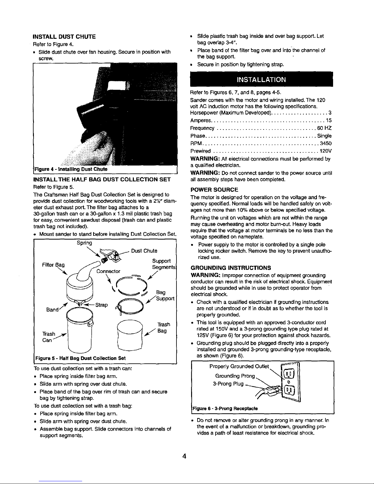
INSTALLDUSTCHUTE
RefertoFigure4.
• Slidedustchuteoverfanhousing.Securein positionwith
screw.
• Slide plastic trash bag inside end over bag support.Let
bag ovedap 3-4",
• Place band of the filter bag overand into the channel of
the bag support.
• Secure in positionby tighteningstrap.
igure 4 - Installing Duet Chute
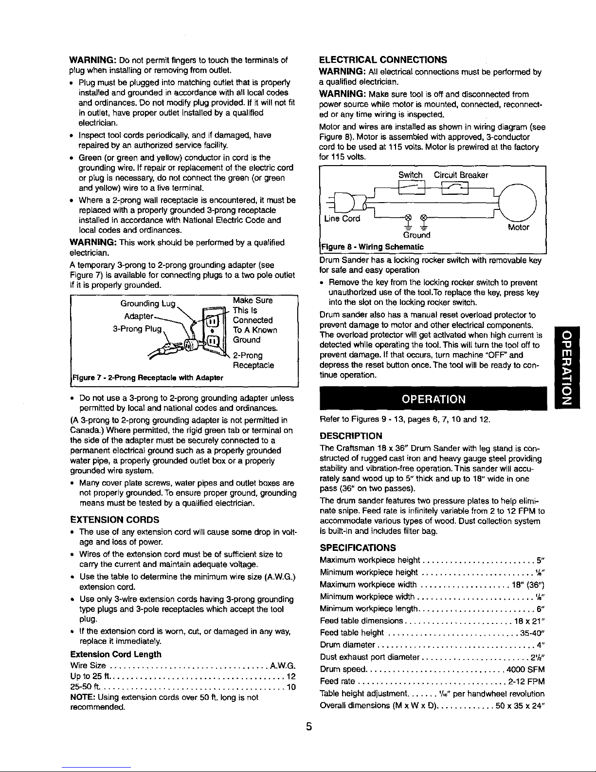
INSTALL THE HALF BAG DUST COLLECTION SET
Refer to Figure 5.
The Craftsman Half Bag Dust Collection Set isdesigned to
providedust collectionfor woodworkingtools with a 2'/="diam-
eter dust exhaust port. The filter bag attaches to a
30-gatlon trash can or a 30-gallon x 1,3 rail plastictrash bag
foreasy, convenient sawdust disposal (trash can and plastic
trash bag not included).
Mount sander to stand before installingDust Collection Set.
Spring
DustChute
• _-,_ _ Support
Filter Bag /_..> Segments
j / Connector i
_' Sag
O */Support
Can _._
Figure 5 - Half Bag Dust Collection Set
Touse dust collectionset with a trash can:
• Place spring inside filter bag arm,
• Slide arm with spring over dust chute.
• Place band of the bag over rim of trash can and secure
bag by tightening strap.
Touse dust collection set with a trash bag:
• Place spring inside filter bag arm.
• Slide arm with spdng over dust chute.
• Assemble bag support. Slide connectors into channels of
supportsegments.
Refer to Figures 6, 7, and 8, pages 4-5.
Sander comes with the motor and wiringinstalled.The 120
volt AC induction motor has the following specifications.
Horsepower (Maximum Developed) .................... 3
Amperes ........................................ 15
Frequency ................................... 60 HZ
Phase....................................... Single
RPM ......................................... 3450
Prewired ..................................... 120V
WARNING: All electrical connections mustbe performed by
a qualified electrician.
WARNING: Do not connect sander to the power source until
an assembly steps have been completed.
POWER SOURCE
The motor is designed for operation on the voltageand fre-
quency specified.Normal loads willbe handled safely onvolt-
ages not more than 10% above or below specifiedvoltage.
Runningthe unit onvoltages whichare not withinthe range
may cause overheating and motorburn-out.Heavy loads
require that the voltage at motor terminals be no less than the
voltage specifiedon nameplate.
• Power supply to the motor iscontrolledby a single pole
looking rocker switch.Remove the key to prevent unautho-
rized use,
GROUNDING INSTRUCTIONS
WARNING: Improper connection of equipment grounding
conductorcan resultinthe risk of electricalshock. Equipment
should be grounded while in use to protect operator from
electricalshock.
• Check with a qualified electrician if groundinginstructions
are not understood or if in doubt as to whether the tool is
propedy grounded.
• This tool is equipped with an approved3-conductor cord
rated at 150V and a 3-prong groundingtype plug rated at
125V (Figure 6) for your protectionagainst shock hazards.
• Grounding plug should be plugged directly into a properly
installed and grounded 3-prong greunding-type receptacle,
as shown (Figure 6).
Preperly Grounded Outlet F/_
Grounding Prong_ II
3-Prong Plug _
Figure 6 - 3-prong Receptacle
• De not remove or alter groundingprong in any manner. In
the eventof a malfunction or breakdown, groundingpro-
videsa path of least resistancefor electrical shock.
4
WARNING: Do not permit fingers to touch the terminals of
plug when installing or removing from outlet.
• Plug must be plugged into matching outlet that is properly
installedand grounded in accordance with all local codes
and ordinances. Do not modify plugprovided. If itwill not fit
in outlet, have proper outlet installed by a qualified
electrician.
• Inspect tool cords periodically, and if damaged, have
repaired by an authorized service facility.
• Green (or green and yellow) conductor in cord is the
groundingwire. If repair or replacement of the electric cord
or plug is necessary, do not connect the green (or green
and yellow) wire to a live terminal.
• Where a 2-prong wall receptacle is encountered, it must be
replaced with a properly grounded 3-prong receptacle
installed in accordance with National Electric Cede and
local codes and ordinances.
WARNING: This work shouldbe performed by a qualified
electrician.
A temporary 3-prong to 2-prong groundingadapter (see
Figure 7) is available for connecting plugs to a two pole outlet
if it is properly grounded.
Grounding Make Sure
This Is
Connected
3-Prong Plug ToA Known
Ground
,2-Prong
Receptacle
Figure7 - 2-Preng ReceptaclewithAdapter
• Do not use a 3-prong to 2-prong grounding adapter unless
permittedby local and national codes and ordinances.
(A 3-prong to 2-preng grounding adapter is not permitted in
Canada.) Where permitted, the rigid green tab or terminal on
the side of the adapter must be securely connected to a
permanent electrical groundsuch as a properly grounded
water pipe, a properly grounded outlet box or a properly
grounded wire system.
• Many cover plate screws, water pipes and outlet boxes are
not properly grounded. To ensure proper ground, grounding
means must be tested by a qualified electrician.
EXTENSION CORDS
• The use of anyextension cord will cause some drop in volt-
age and lossof power.
• Wires ofthe extension cord mustbe of sufficientsize to
carry the current end maintain adequate voltage.
• Use the ta_e to determine the minimumwire size (A,W.G.)
extension cord.
Use only 3-wire extension cords having 3-prong grounding
type plugs and 3-pole receptacles which accept the tool
plug,
If the extensioncord is worn, cut, or damaged in any way,
replace it immediately.
Extension Cord Length
Wire Size ................................... A.W,G.
Up to 25 tt....................................... 12
25-50 ft......................................... 10
NOTE: Using extension cords over 50 ft. long is not
recommended.
ELECTRICAL CONNECTIONS
WARNING: All electrical connectionsmust be performedby
a qualified electrician.
WARNING: Make sure tool is off and disconnected from
power soume while motor is mounted, connected, reconnect-
ed or any time wiring is inspected.
Motor and wires are installed as shown in wiringdiagram (see
Figure 6). Motor is assembled with approved, 3-oonductor
cordto be used at 115 volts. Motor is prewired at the factory
for 115 volts.
Switch CircuitBreaker
Ground
:igure 8 - Wiring Schematic
Drum Sander has a locking rocker switchwith removable ke
for safe and easy operation
• Remove the key from the Iook_]ngrocker switch to prevent
unauthorized use of the tool.Toreplace the key, press key
into the slot on the locking rocker switch.
Drum sander also has a manual reset overload protectorto
prevent damage to motor and other electrical components.
The overload protector will get activated when high current is
detected while operating the tool. This will turn the tool off to
prevent damage. If that occurs, turn machine "OFF" and
depress the reset button once. The tool will be ready to con-
tinue operation.
Refer to Figures 9 - 13, pages 6, 7, 10 and 12.
DESCRIPTION
The Craftsman 18 x 36" Drum Sander with leg stand is con-
strocted of rugged cast iron and heavy gauge steel providing
stability and vibration-free operation. This sander will accu-
rately sand wood up to 5" thick and up to 18" wide in one
pass (36" on two passes).
The drum sander features two pressure plates to help elimi-
nate snipe. Feed rate is infinitely variable from 2 to 12 FPM to
accommodate various types of wood. Dust collection system
is built-in and includes filter bag.
SPECIFICATIONS
Maximum workplace height ......................... 5"
Minimumworkplace height ......................... %"
Maximum workplace width .................... 18" (36")
Minimumworkpiece width .......................... %"
Minimumworkpiece length .......................... 6"
Feed table dimensions ........................ 18 x 21"
Feed table height ............................. 35-40"
Drum diameter ................................... 4"
Dust exhaust port diameter ........................ 2'/z"
Drum speed............................... 4000 SFM
Feed rate ................................. 2-12 FPM
Table height adjustment....... _/,6"per handwheel revolution
Overall dimensions (M x W x D) ............. 50 x 35 x 24"

Switch.................... 120 Volts, SP,Locking rocker
Motor ................. 3HP (max, developed) 3450 RPM,
.................................... 115V,17 AMPS
.Weight ..................................... 198 Ibs
WARNING: Operation of any power tool can result in foreign
objectsbeingthrown into eyes which can result in severe eye
damage. Always wear safety goggles complyingwith United
States ANSI Z87.1 (shown on package) before commencing
powertooloperation. Safety goggles are available at Sears
retail stores or catalog,
CAUTION: Alwaysobserve the following safety precautions.
SAFETY PRECAUTIONS
• Whenever adjustingorreplacing any parts on the tool,turn
switchOFF and remove the plug from power source.
• Make sure all guards are properlyattached. All guards
should be securely fastened.
• Make sure all moving parts are free and clear of any
interference.
• Make sure all fasteners are tight and have not vibrated
loose.
• Always use the dust collection system provided with this
tool.
• Always wear eye protection or face shield.
• Make sure feed belt tracks properly. Correct tracking gives
optimumperformance.
• After turning switchon, always allow drum to come up to
full speed before sanding.
• Clear the feed table of aUobjects (tools,scrap, etc.) before
starting tool.
• Keep yourhands clear of abrasive belt and allmovingparts.
• For optimum performance, do not stall motor or reduce
speed. Do not force the work into the abrasive.
• Support long or wide workpieces with a roller stand at table
height.
• Never push a sharp corner of the workpiece rapidly against
belt. Abrasive backing may tear.
• Replace abrasive when they become loaded (glazed) or
frayed. Check belts fortightness.
• This tool is designed to sand wood or wood productsonly.
Do not attempt to sand metal on thistool.
• Do not sand pieces ofmaterial that are shorter than 6" in
length or thinnerthat Ys".
• Prevent the workpiece from contacting the sandingbelt
before starting the tool.
• Sand with the grain of the wood.
• Never perform layout, assembly,or set-up workon the table
when the tool is operating.
• Turn the tool"OFF", disconnectthe tool from the power
source,and clean the table/work area before leaving the
tool,
• Never leave the work area when the power is =ON", or
before the tool has come to a complete stop.
WARNING: Some dust created by power sanding, sawing,
grinding,drillingand other constructionactivitiescontains
chemicals known to cause cancer, birth defects or other
reproductiveharm.
Some examples of these chemicals are:
• Lead from lead-based paints.
• Crystalline silicafrom bricksand cement and other
masonry products.
• Arsenic and chromium from chemically-traatedlumber.
Yourrisk from these exposures vary,depending on how often
you do this type ofwork.To reduce your exposureto these
chemicals:work in a web ventilated area and work with
approved safety equipment.Always wear MSHA/NIOSH
approved, properlyfitting face mask or respiratorwhen using
such tools.
OPERATING CONTROLS AND ADJUSTMENTS
RefartoFigure9,
ON/OFF Switch
The ON/OFF switch is located at the top of the front panel of
the sander.To turnthe sander ON, move the switch to the up
position. To turn the saw OFF, move the switchto the down
position.
Circuit Breaker
The sander is equipped with a motor protectiondevice-cireuit
breaker.The breaker will automatically shutthe sander off
when excessivecurrent is consumed.
if the breaker is tripped, turn the sander off and reset the cir-
cuit by pressing the button.
CAUTION: Besure to turnthe sander off prior to resetting
the circuitbreakerto avoidunintentionalstart-up of the sander.
Cimuit
Breaker
ON/OFF
Feed Belt
Indicator
Feed Belt
Control
Figure 9 - Operating Controls
 Loading...