

Craftsman 351184300 Owner’s Manual
Operator's Manual
CRRFTSMRN
2 - 31/2"Length
ANGLE FRAMING NAILER
Model No. 351.184300
CAUTION:
Read and follow all Safety
Rules and Operating
Instructions before First
Use of this Product.
Sears, Roebuck and Co., Hoffman Estates, IL 60179 U.S.A.
www.sears.com/craftsman
17414.01 Draft (08/26/02)
• Safety
• Operation
• Maintenance
• Parts List
• Espahol
Warranty ....................................... 2
Safety Rules .................................... 2
Operation .................................... 2-4
Maintenance .................................... 5
Troubleshooting ................................. 6
Parts Illustration and List ......................... 8-9
Espa_ol .................................... 10-14
FULL ONE YEAR WARRANTY ON CRAFTSMAN
FRAMING NAILER
If this product fails due to a defect in material or workmanship
within one year from the date of purchase, Sears will at its
option repair or replace it free of
charge. Contact your nearest Sears Service Center
(1-800-4-MY-HOME) to arrange for product repair, or return
this product to place of purchase for replacement.
If this product is used for commercial or rental purposes, this
warranty will apply for 90 days from the date of purchase.
This warranty applies only while this product is used in the
United States.
This warranty gives you specific legal rights and you may also
have other rights which vary from state to state.
Sears, Roebuck and Co., Dept. 817WA, Hoffman Estates,
IL 60179
• Air tool operators and all others in work area should
always wear safety goggles complying with United States
ANSI Z87.1 to prevent eye injury from fasteners and flying
debris when loading, operating or unloading this tool.
• Never exceed operating pressure of 110 PSI.
• Always keep hands and body away from the fastener dis-
charge area when air supply is connected to tool.
• Always disconnect tool from air supply when servicing or
adjusting tool and when tool is not in use.
• Do not operate when contact trip is not in contact with
work.
• Never load the tool until you are ready to use it.
• Never depress tool trigger when loading.
• Always load with nose of tool pointing away from you and
others.
• Never point tool at yourself or others.
• Never carry tool with trigger depressed.
• Do not use oxygen, combustible gas or high pressure
compressed gas as the air supply for the tool.
• Always use tool at safe distance from other people in work
area.
• Do not attempt to discharge fastener into hard or brittle
materials such as concrete, steel or tile.
• Do not connect female quick-disconnect coupling to tool
side of air line.
© Sears, Roebuck and Co.
• Connect male, free-flow nipple to tool side of air line
connection so that tool is depressurized when hose is
disconnected.
• Do not use a hose swivel with this tool.
• Use Sears recommended fasteners only.
DESCRIPTION
The Craftsman Framing Nailer drives nails from. 113" to. 131"
diameter and from 2" to 31/2"long. Magazine is angled at 28° for
nailing in tight spots such as when toenailing. High strength
magnesium body and aluminum components are lightweight
and durable. Safety feature disables tool unless contact trip is
pressed against workpiece. Sequential trigger switch allows
selection of rapid-fire or single-fire mode. Contact trip can be
adjusted for setting nail depth. Pusher mechanism supports
shorter fasteners to prevent jamming. Plastic protector on the
end of contact trip prevents marring of workpiece. Large capac-
ity, side load magazine makes it easy to load up to 100 stick
nails at a time. Tool drives straight, screw, and ring shank nails.
Exhaust deflector can be rotated 360°.The Angle Framing
Nailer is excellent for truss making, framing, sheathing, sub-
flooring and decking.
SPECIFICATIONS
Capacity ............................ 72 to 100 nails
Nail size ............................... 113 to .131"
Nail lengths ............................... 2 to 3W'
Operating pressure ..................... 70 to 110 PSI
Air inlet .................................. 1/4"N.RT.
Length ....................................... 19"
Height ...................................... 141/4''
Width ....................................... 51/8"
Weight ..................................... 7 Ibs.
NAILS
18351 ............... 8 penny, .120" diameter x 21/2"long
18352 ............... 10 penny, .120" diameter x 3" long
18353 .............. 16 penny, .131" diameter x 31/S' long
GALVANIZED NAILS
18357 ............... 8 penny, .120" diameter x 21/S' long
18358 ............... 10 penny, .120" diameter x 3" long
18359 .............. 16 penny, .131" diameter x 31/S' long
AIR SUPPLY LINE
Refer to Figure 1 (page 3).
• The air tool operates on compressed air at pressures from
70 to110PSI.
• Never exceed maximum pressure.
Air Delivery Required: 2.21 SCFM @ 90 PSI
(30 shots per minute).
WARNING: Keep hands and body away from discharge area
of tool when connecting air supply. Always disconnect tool
from air supply when servicing or adjusting tool and when tool
is not in use.
• Air operated tools require clean, dry, lubricated com-
pressed air to ensure top performance, low maintenance
and long life.
2
• Dirt and abrasive materials present in all air lines will dam-
age tool O-rings, valves and cylinders.
• Moisture will reduce tool performance and life if not
removed from compressed air.
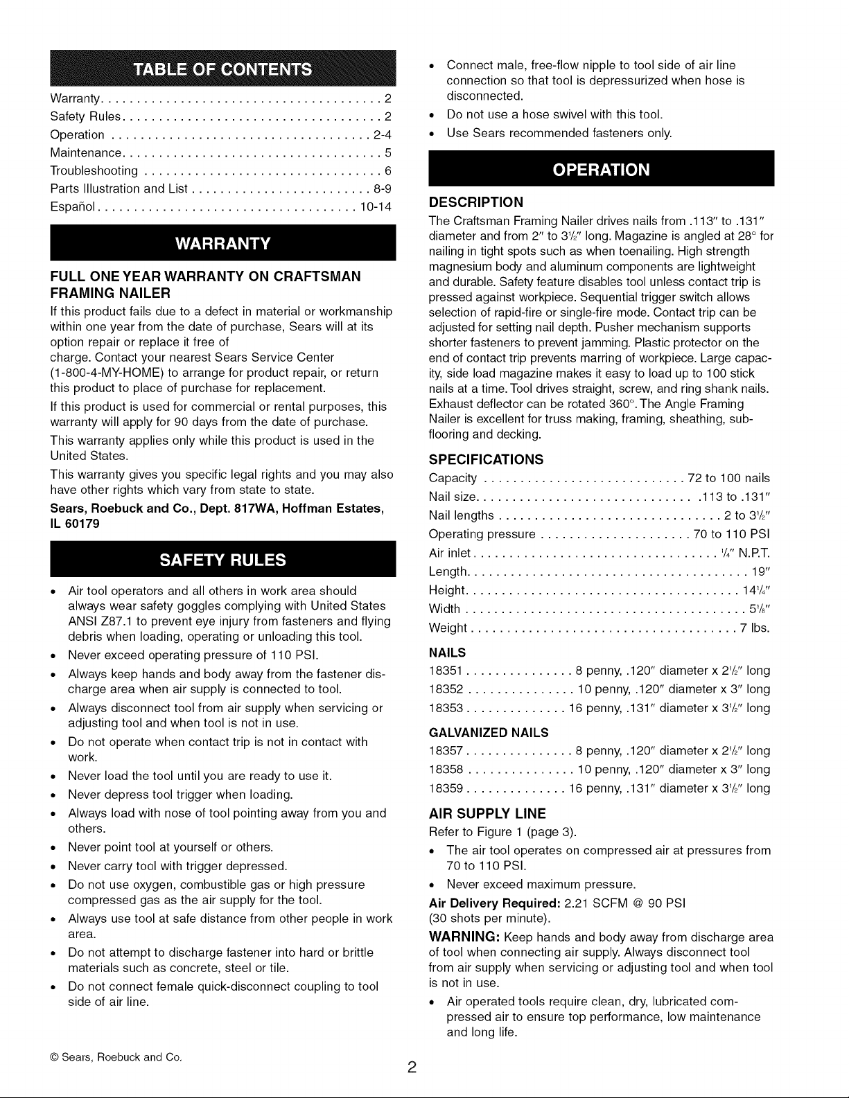
• A filter-regulator-lubricator system is required and should be
located as close to tool as possible (see Figure 1). A dis-
tance of less than 15 feet is recommended.
• Keep air filter clean. A dirty filter will reduce the air pressure
to the tool causing a reduction in power and efficiency.
• The air supply system must be able to provide air pressure
of 70 to 110 pounds per square inch at tool.
• All hoses and pipes in the air supply system must be clean
and free of moisture and foreign particles.
• Do not mount swivel connector in air supply line.
• The air pressure should be properly regulated.
• Different workpiece materials and different fastener lengths
will require different operating pressure.
• Be sure all connections in air supply system are sealed to
prevent air loss.
• Never connect a female quick-connect coupling to the tool
side of air line connection. A male, free-flow coupling
should be connected to the tool side of air.
WARNING: The female coupling provides a seal preventing
loss of compressed air from compressor tank when discon-
nected from male coupling. If connected to tool side of air sup-
ply, the female coupling could seal a compressed air charge in
the tool which could discharge if the tool trigger is actuated.
2 Foot Hose Whip
Male Quick-Connect-
Figure 1 - Air Supply Line
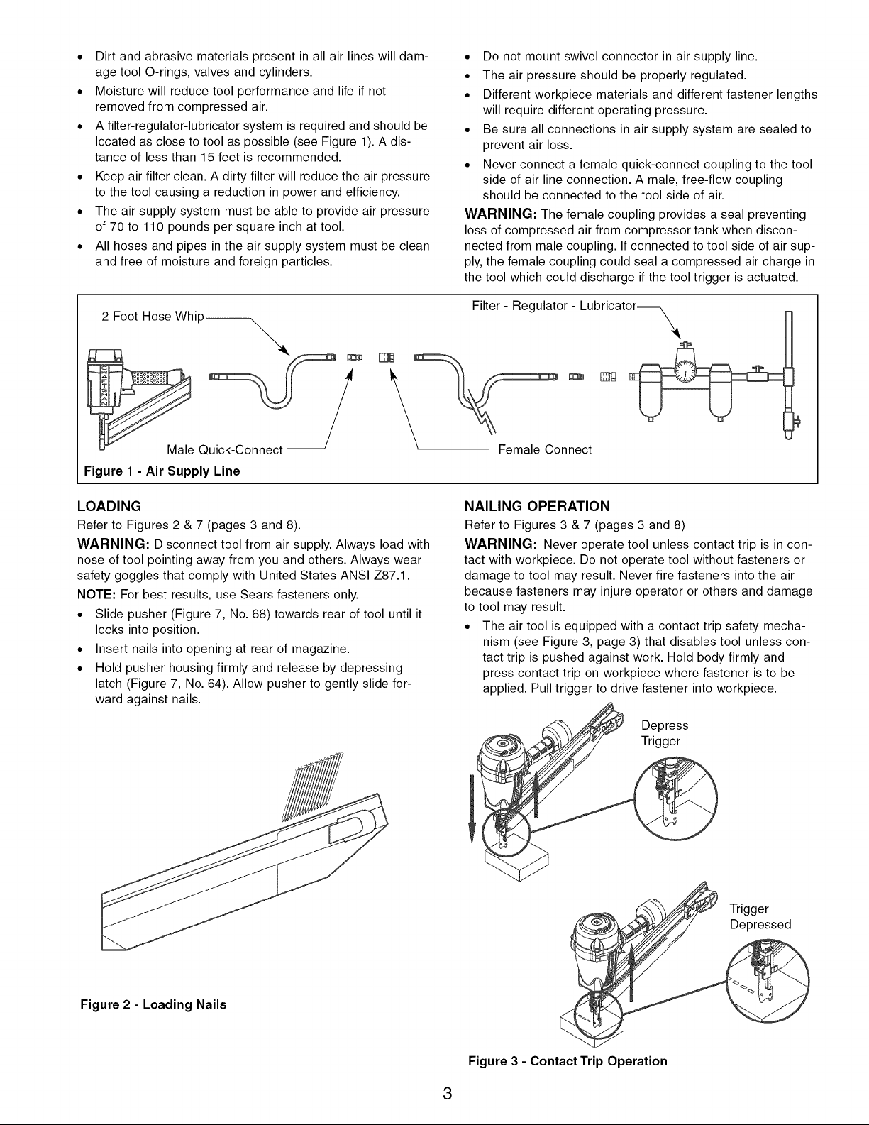
LOADING
Refer to Figures 2 & 7 (pages 3 and 8).
WARNING: Disconnect tool from air supply. Always load with
nose of tool pointing away from you and others. Always wear
safety goggles that comply with United States ANSI Z87.1.
NOTE: For best results, use Sears fasteners only.
• Slide pusher (Figure 7, No. 68) towards rear of tool until it
locks into position.
• Insert nails into opening at rear of magazine.
• Hold pusher housing firmly and release by depressing
latch (Figure 7, No. 64). Allow pusher to gently slide for-
ward against nails.
Filter - Regulator - Lubricator_
o
nnect
NAILING OPERATION
Refer to Figures 3 & 7 (pages 3 and 8)
WARNING: Never operate tool unless contact trip is in con-
tact with workpiece. Do not operate tool without fasteners or
damage to tool may result. Never fire fasteners into the air
because fasteners may injure operator or others and damage
to tool may result.
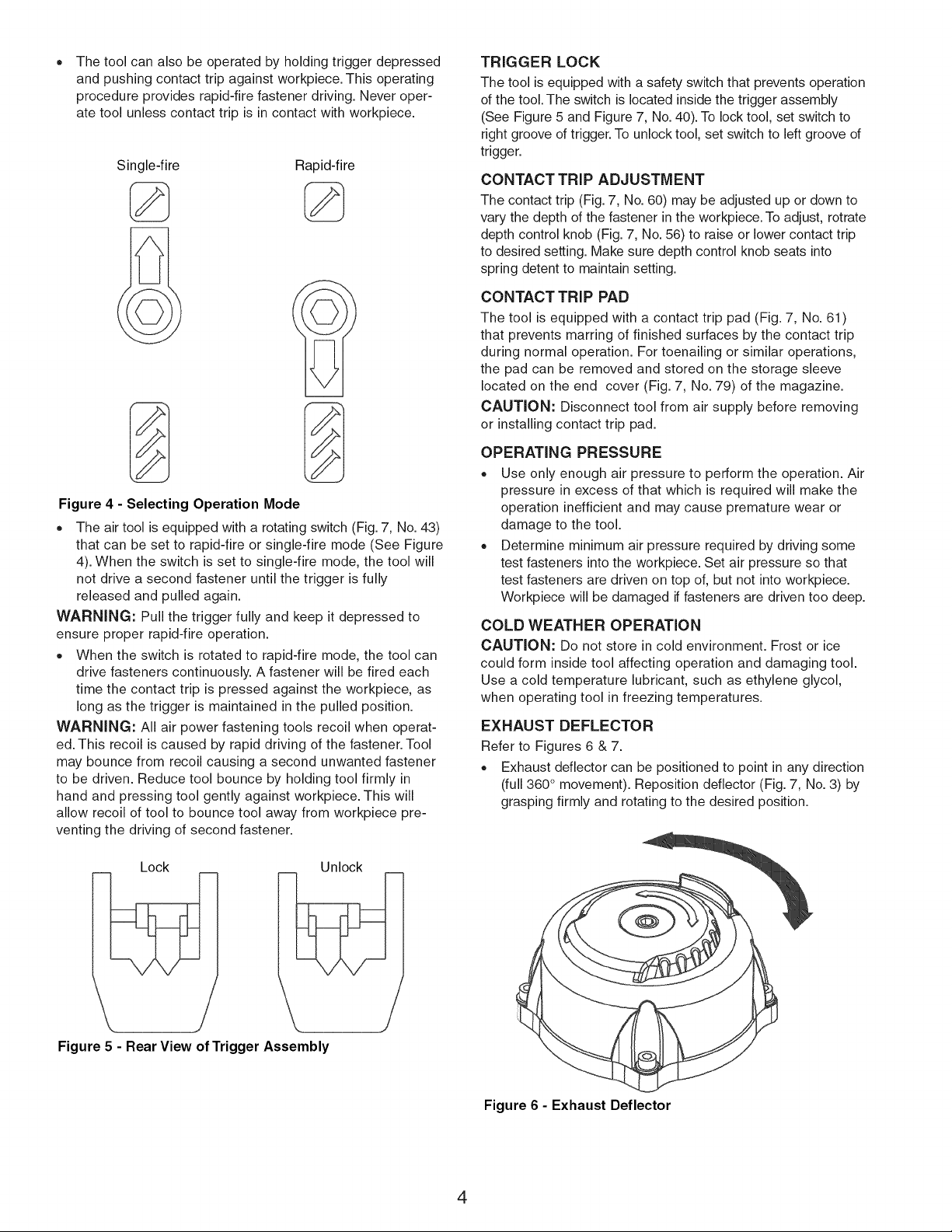
• The air tool is equipped with a contact trip safety mecha-
nism (see Figure 3, page 3) that disables tool unless con-
tact trip is pushed against work. Hold body firmly and
press contact trip on workpiece where fastener is to be
applied. Pull trigger to drive fastener into workpiece.
Figure 2 - Loading Nails
Depress
Trigger
Depressed
Trigger
Figure 3 - Contact Trip Operation
3
The tool can also be operated by holding trigger depressed
and pushing contact trip against workpiece. This operating
procedure provides rapid-fire fastener driving. Never oper-
ate tool unless contact trip is in contact with workpiece.
Single-fire Rapid-fire
Figure 4 - Selecting Operation Mode
• The air tool is equipped with a rotating switch (Fig. 7, No. 43)
that can be set to rapid-fire or single-fire mode (See Figure
4). When the switch is set to single-fire mode, the tool will
not drive a second fastener until the trigger is fully
released and pulled again.
WARNING: Pull the trigger fully and keep it depressed to
ensure proper rapid-fire operation.
When the switch is rotated to rapid-fire mode, the tool can
drive fasteners continuously. A fastener will be fired each
time the contact trip is pressed against the workpiece, as
long as the trigger is maintained in the pulled position.
WARNING: All air power fastening tools recoil when operat-
ed. This recoil is caused by rapid driving of the fastener. Tool
may bounce from recoil causing a second unwanted fastener
to be driven. Reduce tool bounce by holding tool firmly in
hand and pressing tool gently against workpiece. This will
allow recoil of tool to bounce tool away from workpiece pre-
venting the driving of second fastener.
TRIGGER LOCK
The tool is equipped with a safety switch that prevents operation
of the tool. The switch is located inside the trigger assembly
(See Figure 5 and Figure 7, No. 40). To lock tool, set switch to
right groove of trigger. To unlock tool, set switch to left groove of
trigger.
CONTACT TRIP ADJUSTMENT
The contact trip (Fig. 7, No. 60) may be adjusted up or down to
vary the depth of the fastener in the workpiece. To adjust, rotrate
depth control knob (Fig. 7, No. 56) to raise or lower contact trip
to desired setting. Make sure depth control knob seats into
spring detent to maintain setting.
CONTACT TRIP PAD
The tool is equipped with a contact trip pad (Fig. 7, No. 61)
that prevents marring of finished surfaces by the contact trip
during normal operation. For toenailing or similar operations,
the pad can be removed and stored on the storage sleeve
located on the end cover (Fig. 7, No. 79) of the magazine.
CAUTION: Disconnect tool from air supply before removing
or installing contact trip pad.
OPERATING PRESSURE
• Use only enough air pressure to perform the operation. Air
pressure in excess of that which is required will make the
operation inefficient and may cause premature wear or
damage to the tool.
• Determine minimum air pressure required by driving some
test fasteners into the workpiece. Set air pressure so that
test fasteners are driven on top of, but not into workpiece.
Workpiece will be damaged if fasteners are driven too deep.
COLD WEATHER OPERATION
CAUTION: Do not store in cold environment. Frost or ice
could form inside tool affecting operation and damaging tool.
Use a cold temperature lubricant, such as ethylene glycol,
when operating tool in freezing temperatures.
EXHAUST DEFLECTOR
Refer to Figures 6 & 7.
Exhaust deflector can be positioned to point in any direction
(full 360 ° movement). Reposition deflector (Fig. 7, No. 3) by
grasping firmly and rotating to the desired position.
Lock Unlock
Figure 5 - Rear View of Trigger Assembly
Figure 6 - Exhaust Deflector
4
Refer to Figure 7 (page 8).
LUBRICATION
Lubricate nailer daily with quality air tool oil. If no air line lubri-
cator is used, place five or six drops of oil into air inlet cap
(Fig. 7, No. 24) of tool everyday.
MAGAZINE AND PISTON/RAM
• Keep magazine and contact trip area clean and free of any
dirt, lint or abrasive particles.
The tip of the ram (Fig. 7, No. 16) can become dented or
rounded over time.
• Square off the tip of the ram with a clean, fine hand file to
extend the life of the ram and tool. Fastener firing will be
more consistent if the ram tip is kept clean and square.
SAFETY MECHANISM
Refer to Figure 4.
Inspect contact trip safety mechanism daily for proper opera-
tion. Do not operate tool if mechanism is not operating properly.
With the switch (Fig. 7, No. 43) set to the single-fire mode, per-
form the following procedures to test the safety mechanism:
° Leave trigger untouched while pushing contact trip into
workpiece. Tool must not fire.
° Pull trigger while contact trip is clear of work and pointed
away from operator and others. Tool must not fire.
° Push contact trip against work where fastener is needed
and flick trigger. The tool should drive only one fastener
each time the contact trip is pushed against workpiece and
trigger is flicked.
If contact trip mechanism does not operate properly,
repair tool immediately through Sears Service Center.
Replace any damaged or missing parts. Use the parts list to
order parts.
REBUILD KITS
Rebuild kits are available as spare parts, (see page 9).Tools
should be rebuilt iftool fails to operate properly after extended use.
See troubleshooting to determine required replacement parts.
Disconnect tool from air supply before attempting repair
or adjustment.
NOTE: When replacing O-rings or cylinder, lubricate with air
tool oil before assembly.
5
 Loading...