

Craftsman 351184060 Owner’s Manual
Operator's Manual
CRRFTSMRN
Y."Crown
18 Gauge
%- 1" Length
CROWN STAPLER
Model No.
351.184060
CAUTION: Read and follow
all Safety Rules and Operating
Instructions before First Use
of this Product.
Sears, Roebuck and Co., Hoffman Estates, IL 60179 U.S.A.
4496.01 Draft (11/02/99)
• Safety
• Operation
• Maintenance
• Parts List
• Espa5ol
Warranty ....................................... 2
Safety Rules .................................... 2
Operation .................................... 2-4
Maintenance .................................... 4
Troubleshooting ................................. 5
Parts Illustration and List ......................... 6-7
EspaSol ..................................... 8-11
FULL ONE YEAR WARRANTY ON CRAFTSMAN
AIR-DRIVE TOOLS
If this Craftsman air-drive tool fails due to a defect in material
or workmanship within one full year from the date of
purchase, return it to the nearest Sears Service Center in the
United States, and Sears will repair it free of charge.
If this air-drive tool is used for commercial purposes, this war-
ranty applies for only 90 days from the date of purchase.
This warranty gives you specific legal rights and you may also
have other rights which vary from state to state.
Sears, Roebuck and Co., Dept. 817WA, Hoffman Estates, IL
60179
• Air tool operators and all others in work area should
always wear safety goggles complying with United States
ANSI Z87.1 to prevent eye injury from fasteners and flying
debris when loading, operating or unloading this tool.
• Never exceed operating pressure of 100 PSI.
• Always keep hands and body away from the fastener dis-
charge area when air supply is connected to tool.
• Always disconnect tool from air supply when servicing or
adjusting tool and when tool is not in use.
• Do not operate when nose of tool is not in contact with
work.
• Never load the tool until you are ready to use it.
• Never depress tool trigger when loading.
• Always load with nose of tool pointing away from you and
others.
• Never point tool at yourself or others.
• Never carry tool with trigger depressed.
• Do not use oxygen, combustible gas or high pressure
compressed gas as the air supply for the tool.
• Always use tool at safe distance from other people in work
area.
• Do not attempt to discharge fastener into hard or brittle
materials such as concrete, steel or tile.
• Do not connect female quick-disconnect coupling to tool
side of air line.
• Connect male, free-flow nipple to tool side of air line so
that tool is depressurized when hose is disconnected.
• Do not use a hose swivel with this tool.
• Use Sears recommended fasteners only.
DESCRIPTION
The Craftsman '_" Crown Stapler drives _" crown, 18 gauge
staples from %to 1" long. Oilless design eliminates daily oil-
ing and oil stains on workpiece. Die cast aluminum body with
textured grip minimizes operator fatigue. Large capacity, top
loading magazine with positive quick action latch makes load-
ing easy. Safety feature disables tool unless contact trip is
pressed against workpiece. Tapered nosepiece provides oper-
ator with greater visibility for precise fastener placement. Rigid
nosepiece reduces jamming. The '¼"Crown Stapler is excel-
lent for furniture making, upholstery, cabinetry and picture
framing.
SPECIFICATIONS
Capacity ............................... 120 staples
Staple crown width .............................. '_"
Staple lengths .............................. 3/8to 1"
Staple size .................... 18 gauge (.049 x .040")
Operating pressure ....................... 60-100 PSI
Air inlet .................................. '_" N.P.T.
Length ...................................... 9_ ''
Height ....................................... 7'_''
Width ....................................... 2_ ''
Weight ................................... 2.05 Ibs.
STAPLES
18333 ............................ '_" crown, _/2"long
18334 ............................ '/4" crown, 3/4"long
18336 ............................ '/4" crown, 7/8"long
18371 ............................ '/_" crown, 1" long
AIR SUPPLY LINE
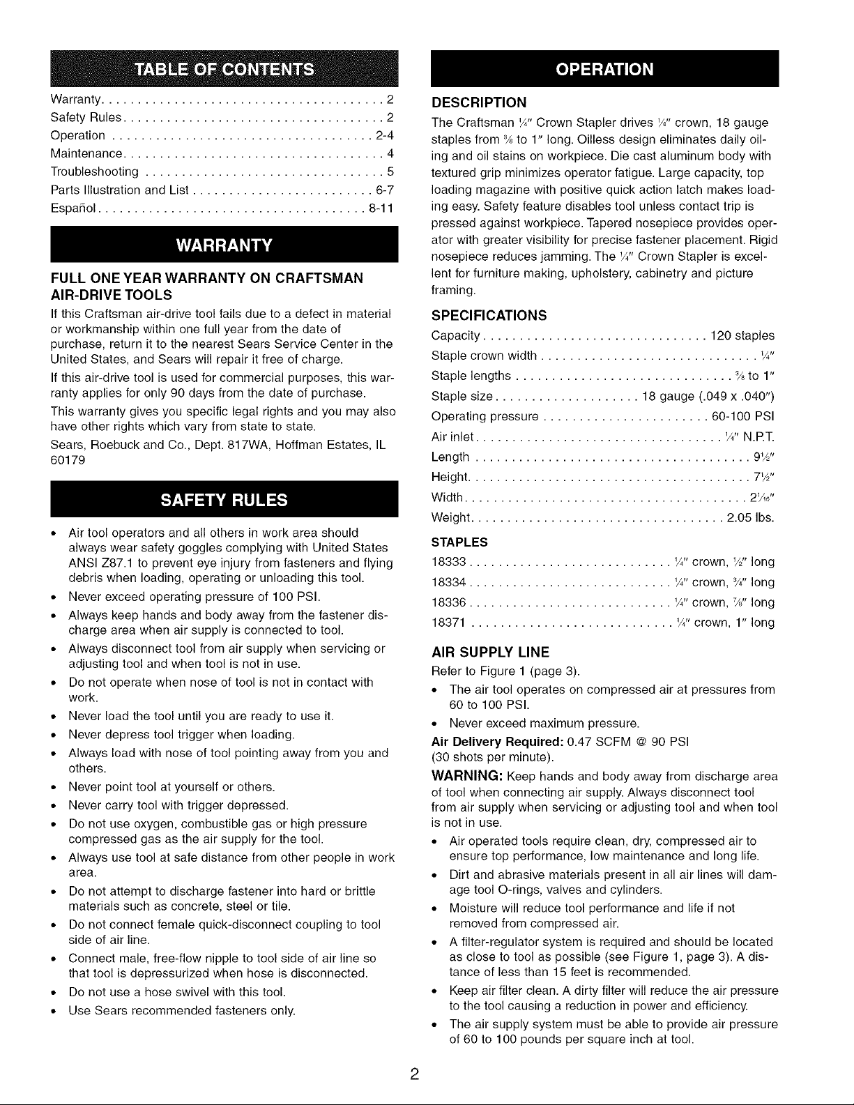
Refer to Figure 1 (page 3).
° The air tool operates on compressed air at pressures from
60 to 100 PSI.
° Never exceed maximum pressure.
Air Delivery Required: 0.47 SCFM @ 90 PSI
(30 shots per minute).
WARNING: Keep hands and body away from discharge area
of tool when connecting air supply. Always disconnect tool
from air supply when servicing or adjusting tool and when tool
is not in use.
° Air operated tools require clean, dry, compressed air to
ensure top performance, low maintenance and long life.
° Dirt and abrasive materials present in all air lines will dam-
age tool O-rings, valves and cylinders.
° Moisture will reduce tool performance and life if not
removed from compressed air.
° A filter-regulator system is required and should be located
as close to tool as possible (see Figure 1, page 3). A dis-
tance of less than 15 feet is recommended.
° Keep air filter clean. A dirty filter will reduce the air pressure
to the tool causing a reduction in power and efficiency.
° The air supply system must be able to provide air pressure
of 60 to 100 pounds per square inch at tool.
2
° All hoses and pipes in the air supply system must be clean
and free of moisture and foreign particles.
° Do not mount swivel connector in air supply line.
° The air pressure should be properly regulated.
° Different workpiece materials and different fastener lengths
will require different operating pressure.
° Be sure all connections in air supply system are sealed to
prevent air loss.
2 Foot
Hose Whip
Quick-Disconnect
Male
Figure 1 - Air Supply Line
° Never connect a female quick-disconnect coupling to the
tool side of air line connection. A male, free-flow coupling
should be connected to the tool side of air line connection.
WARNING: The female coupling provides a seal preventing
loss of compressed air from compressor tank when discon-
nected from male coupling. If connected to tool side of air
supply, the female coupling could seal a compressed air
charge in the tool which could discharge if the tool trigger is
actuated.
Filter - Regulator__ t
Female Quick-Disconnect
LOADING
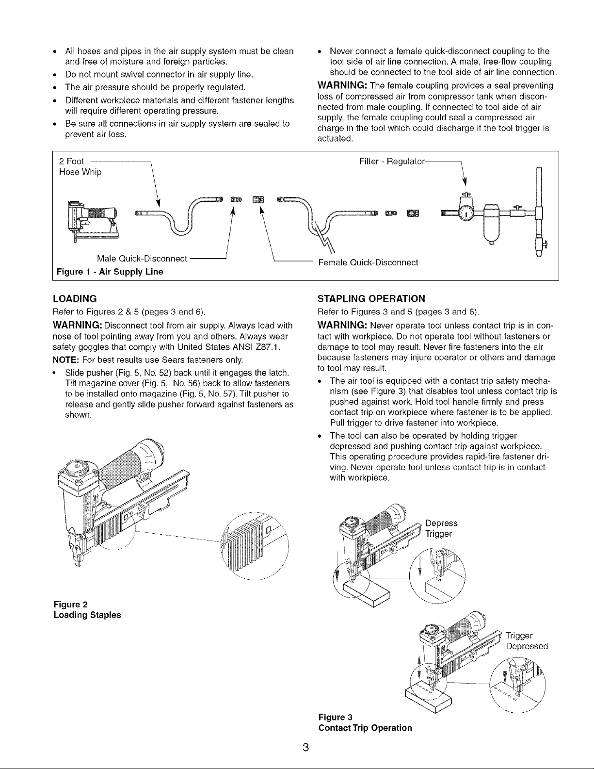
Refer to Figures 2 & 5 (pages 3 and 6).
WARNING: Disconnect tool from air supply. Always load with
nose of tool pointing away from you and others. Always wear
safety goggles that comply with United States ANSI Z87.1.
NOTE: For best results use Sears fasteners only.
• Slide pusher (Fig. 5, No. 52) back until it engages the latch.
Tilt magazine cover (Fig. 5, No. 56) back to allow fasteners
to be installed onto magazine (Fig. 5, No. 57). Tilt pusher to
release and gently slide pusher forward against fasteners as
shown.
STAPLING OPERATION
Refer to Figures 3 and 5 (pages 3 and 6).
WARNING: Never operate tool unless contact trip is in con-
tact with workpiece. Do not operate tool without fasteners or
damage to tool may result. Never fire fasteners into the air
because fasteners may injure operator or others and damage
to tool may result.
° The air tool is equipped with a contact trip safety mecha-
nism (see Figure 3) that disables tool unless contact trip is
pushed against work. Hold tool handle firmly and press
contact trip on workpiece where fastener is to be applied.
Pull trigger to drive fastener into workpiece.
° The tool can also be operated by holding trigger
depressed and pushing contact trip against workpiece.
This operating procedure provides rapid-fire fastener dri-
ving. Never operate tool unless contact trip is in contact
with workpiece.
Depress
Trigger
Figure 2
Loading Staples
Trigger
Depressed
Figure 3
Contact Trip Operation
Thetoolisequippedwithapush-buttonswitchthatcan
changetheoperatingmodefromrapid-firetosinglefire.
Whentheredstopbutton(Fig.5,No.47)ispushedinfrom
the"CRAFTSMAN"side,thetoolwillfireonefasteneronly.
Tofirethenextfastener,boththetrigger(Fig.5,No.33)
andthecontacttrip(Fig.5,No.63)mustbereleased.
OPERATINGPRESSURE
o Use only enough air pressure to perform the operation. Air
pressure in excess of that which is required will make the
operation inefficient and may cause premature wear or
damage to the tool.
o Determine minimum air pressure required by driving some
test fasteners into the workpiece. Set air pressure so that
test fasteners are driven down flush with the work surface.
Fasteners driven too deep may damage workpiece.
EXHAUST DEFLECTOR
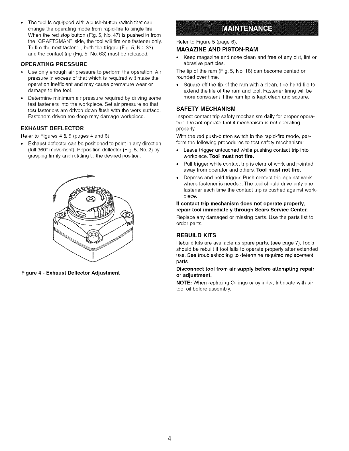
Refer to Figures 4 & 5 (pages 4 and 6).
o Exhaust deflector can be positioned to point in any direction
(full 360 ° movement). Reposition deflector (Fig. 5, No. 2) by
grasping firmly and rotating to the desired position.
Refer to Figure 5 (page 6).
MAGAZINE AND PISTON-RAM
• Keep magazine and nose clean and free of any dirt, lint or
abrasive particles.
The tip of the ram (Fig. 5, No. 18) can become dented or
rounded over time.
• Square off the tip of the ram with a clean, fine hand file to
extend the life of the ram and tool. Fastener firing will be
more consistent if the ram tip is kept clean and square.
SAFETY MECHANISM
Inspect contact trip safety mechanism daily for proper opera-
tion. Do not operate tool if mechanism is not operating
properly.
With the red push-button switch in the rapid-fire mode, per-
form the following procedures to test safety mechanism:
• Leave trigger untouched while pushing contact trip into
workpiece. Tool must not fire.
• Pull trigger while contact trip is clear of work and pointed
away from operator and others. Tool must not fire.
• Depress and hold trigger. Push contact trip against work
where fastener is needed. The tool should drive only one
fastener each time the contact trip is pushed against work-
piece.
If contact trip mechanism does not operate properly,
repair tool immediately through Sears Service Center.
Replace any damaged or missing parts. Use the parts list to
order parts.
Figure 4 - Exhaust Deflector Adjustment
REBUILD KITS
Rebuild kits are available as spare parts, (see page 7). Tools
should be rebuilt if tool fails to operate properly after extended
use. See troubleshooting to determine required replacement
parts.
Disconnect tool from air supply before attempting repair
or adjustment.
NOTE: When replacing O-rings or cylinder, lubricate with air
tool oil before assembly.
4
 Loading...