

Craftsman 351182920 Owner’s Manual
Operator's Manual
CRRFTSMI:INo
23 Gauge
318- _14"Length
HEADLESS PINNER
Model No.
351.182920
CAUTION: Read and follow
all Safety Rules and Operating
Instructions before First Use
of this Product.
Sears, Roebuck and Co., Hoffman Estates, IL 60179 U.S.A.
2697.00 Draft (03/17/99)
• Safety
• Operation
• Maintenance
• Parts List
Warranty ....................................... 2
Safety Rules .................................... 2
Operation .................................... 2-3
Maintenance .................................... 4
TroubleshOoting ................................. 5
Parts Illustrabon and List ......................... 6-7
FULL ONEYEAR WARRANTY ON CRAFTSMAN
AIR-DRIVE TOOLS
If this Craftsman air-drive tool fails due to a defect in material
or workmanship within one full year from the date of
purchase, return it to the nearest Sears Service Center in the
United States, and Sears will repair it free of charge.
If this air-drive tool is used for commercial purposes, this war-
ranty applies for only 90 days from the date of purchase.
This warranty gives you specific legal rights and you may also
have other rights which vary from state to state.
Sears, Roebuck and Co., Dept. 817WA, Hoflman Estates, IL
60179
• Air tool operators and all others in work area should
always wear safety goggles complying with United States
ANSI Z87.1 to prevent eye injury from fasteners and flying
debris when loading, operating or unloading this tool.
Never exceed operating pressure of 100 PSI.
Always keep hands and body away from the fastener dis-
charge area when air supply is connected to tool.
Always disconnect tool from air supply when servicing or
adjusting tool and when tool is not in use.
• Do not operate when nose of tool is not in contact with
work.
Never load the tool until you are ready to use it.
• Never depress tool trigger when loading.
Always load with nose of tool pointing away from you and
others.
Never point tool at yourself or others.
Never carry tool with trigger depressed.
Do not use oxygen, combustible gas or high pressure
compressed gas as the air supply for the tool
Always use tool at safe distance from other people in work
area.
Do not attempt to discharge fastener into hard or brittle
materials such as concrete, steel or tile.
• Do not connect female quick-disconnect coupling to tool
side of air line.
• Connect male, free-flow nipple to tool side of air line so
that tool is depressurized when hose is disconnected.
• Do not use a hose swivel with this tool.
• Use Sears recommended fasteners only.
DESCRIPTION
The Craftsman Headless Pinner ddves 23 gauge pins from _k
to _/," long. 360° directional exhaust prevents staining on
workpiece. Safety trigger guard helps prevent accidental dis-
charge. Die cast aluminum body with textured grip minimizes
operator fatigue. Large capacity, bottom loading magazine
with positive quick action latch makes loading easy. Fast cycle
time increases productivity.Slanted nosepiece provides oper-
ator with greater visibility for precise fastener placement. Rigid
no_Jepiece reduces jamming. The headless pinner is excellent
for molding and decorative trim, glazing strips, mirror and pic-
ture frame assembly, and window beading.
SPECIFICATIONS
Capacity ................................. 200 pins
Pin length ................................. =/,to 3/.
Pin size ........................... 23 gauge (.023")
Operating pressure ....................... 60-100 PSI
Air inlet .................................. '/," N.P.T.
Length ....................................... 8"
Height ........................................ 6"
Width ...................................... 1.75"
Weight ................................... 1.50 Ibs.
AIR SUPPLY LINE
Refer to Figure 1 (page 3).
• The air tool operates on compressed air at pressures from
60 to 100 PSL
• Never exceed maximum pressure.
Minimum air requirements for tool: Average working SCFM
2.6 at 90 PSi.
WARNING: Keep hands and body away from discharge area
of tool when connecting air supply. Always disconnect tool
from air supply when servicing or adjusting tool and when tool
is not in use.
• Air operated tools require clean, dry, compressed air to
ensure top performance, low maintenance and long life.
Dirt and abrasive materials present in all air lines will dam-
age tool O-rings, valves and cylinders.
Moisture will reduce tool performance and life if not
removed from compressed air.
A filter-regulator system is required and should be located
as close to tool as possible (see Figure 1, page 3). A dis-
tance of less than 15 feet is recommended.
Keep air filter clean. A dirty filter will reduce the air pressure
to the toot causing a reduction in power and efficiency.
• The air supply system must be able to provide air pressure
of 60 to 100 pounds per square inch at tool.
• All hoses and pipes in the air supply system must be clean
and free of moisture and foreign particles,
• Do not mount swivel connector in air supply line.
• The air pressure should be properly regulated.
• Different workpiece materials and fastener lengths will
require different operating pressure.
• Be sure all connections in air supply system are sealed to
prevent air loss.
"3
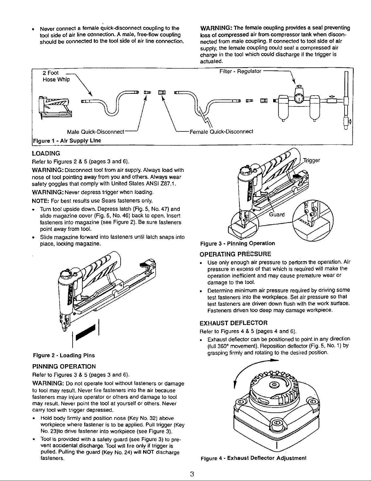
Never connect a female quick-disconnect coupling to the
tool side of air line connection, A mate, free-flow coupling
should be connected to the tool side of air line connection.
WARNING: The female coupling provides a seal preventing
loss of compressed air from compressor tank when diScon-
nected from male coupling. If connected to tool side of air
supply, the female coupling could seal a compressed air
charge in the tool which could discharge if the trigger is
actuated.
Filter - Regulator
Male Quick-Disconnect
Figure I - Air Supply Line
LOADING
Refer to Figures 2 & 5 (pages 3 and 6).
WARNING: Disconnect tool from air supply• Always load with
nose of tool pointing away from you and others• Always wear
safety goggtes that comply with United States ANSI Z87.1.
WARNING: Never depress trigger when loading.
NOTE: For best results use Sears fasteners only.
• Turn tool upside down. Depress latch (Fig. 5, No. 47) and
slide magazine cover (Fig. 5, No. 46) back to open. Insert
fasteners into magazine (see Figure 2). Be sure fasteners
point away from tool.
• Slide magazine forward into fasteners until latch snaps into
place, locking magazine.
Female Qu=ck Disconnect
Figure 3 - Pinning Operation
OPERATING PRE_,SURE
• Use only enough air pressure to perform the operation. Air
pressure in excess of that which is required will make the
operation inefficient and may cause premature wear or
damage to the tool.
• Determine minimum air pressure required by driving some
test fasteners into the workpiece. Set air pressure so that
test fasteners are driven down flush with the work surface.
Fasteners driven too deep may damage workpiece.
Figure 2 - Loading Pins
PINNING OPERATION
Refer to Figures 3 & 5 (pages 3 and 6).
WARNING: Do not operate tool without fasteners or damage
to tool may result. Never fire fasteners into the air because
fasteners may injure operator or others and damage to tool
may result• Never point the tool at yourself or others. Never
carry tool with trigger depressed.
Hold body firmly and position nose (Key No. 32) above
workpiece where fastener is to be applied. Pull trigger (Key
No. 23)to drive fastener into workpiece (see Figure 3).
Tool is provided with a safety guard (see Figure 3) to pre-
vent accidental discharge• Tool will fire only if trigger is
pulled• Pulling the guard (Key No. 24) will NOT discharge
fasteners•
EXHAUST DEFLECTOR
Refer to Figures 4 & 5 (pages 4 and 6).
• Exhaust deflector can be positioned to point inany direction
(full 360° movement)• Reposition deflector (Fig. 5, No. 1) by
grasping firmly and rotating to the desired position.
Figure 4 - Exhaust Deflector Adjustment
3
 Loading...