

Craftsman 351182010, 351182000 Owner’s Manual
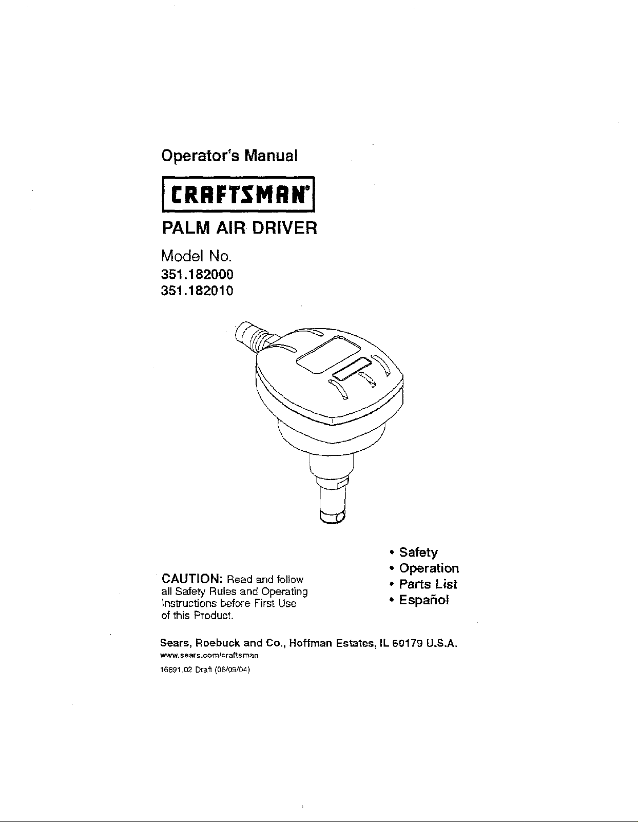
Operator's Manual
PALM AIR DRIVER
Model No.
351.182000
351.182010
• Safety
• Operation
CAUTION: Read and follow
all Safety Rules and Operating
Instructions before First Use
of _is Product.
Sears, Roebuck and Co., Hoffman Estates, IL 60179 U.S.A.
W_W.se_rs,com/_r aft smz_n
16891,02 Draft (06/09/04)
• Parts List
• EspaSol
Warranty ........................ 2 Troubleshooting ................. 5
Safety Rules .................... 2 Parts tilusttation and List ........ 6-7
Operation .................... 2-3 Espafol ..................... 8-11
FULL ONE YEAR WARRANTY
If th_sproduct fails due to a defect in material or workmanship within one year from
the date of purchase. Sears will at its option repair or repines it tree of charge.
Contact your nearest Sears _arvise Cantar (1-BOO-4-MY-HOME) to arrange for
product repair, or return this product to place of pursh_se for replaeemant.
If this product is used for commeroia_ or rental purposes, this warranty will appty for
90 days from the date of purchase.
This warranty applies only while this product is in the United States.
This warranty gives you specific legal rights and you may at_o have other fights
which vary from state to stats.
Sears, Roebuck and Ca., DapL 817WA, Hoffraan Esttates, IL 60179
• Air too_operators and all others in
work area shoutd always wear safety
goggles complying with United
States ANSI Z87.1 to prevent eye
injury from fasteners and flying
debris when loading, operating or
unloa_ng this too!.
• Never exceed operating pressure of
100 PSI.
• Always keep hands and body aWay
from the fastener discharge area
when air euppty is connected to tool
• Always disconnect to01 from air sup-
ply when servicing or a_usting tool
and when tool is not in use.
• Never point tool at yourself or others.
DESCRIPTION
The Craftsman Palm Air Driver (Model
182000) drives 3/4-5%"long nails.
Lightweight die cast aluminum body
provides easy maneuverability where
hammers and other fobls will not work.
© Sears, Roebuck and Co.
Do not use oxygen, combustible g_
or high pressure compressed gas as
the air supply for the too[.
• Always use tool at safe distance
from other people in work area..
• bo not attempt to di._harge fastener
intohard or brittle matefiats such as
Concrete, etse! or tile.
• [30 not connect female quick-connect
coupling to tool side of air line.
• Connect male, free-flow nipple to
tool side of air line so that tool is
deprassunzed when hose is _seon-
neoted.
Do not use a hose swivel with this
tool
Ddver has a magnetic nose to hold
nails for accurate, safe placement. The
Craftsman Palm Air Driver is ideal for
installation of electricat boxes, rafter
bracing, joint hangers, fencing, decking
and framing.
"73_eCraftsman Palm Air Dr_ver Ki_
(Model 182010) includes palm air driver
plus storage case, glove, V," NPT quick
¢ony_ector, rnaintenanee kit, wrenches,
air tool oil, large nail and finish nail
guide bushings.
SPECIFICATIONS
Nail length 3/,. 5V2"(2d-50d)
Nail head size (die.)
18200 .................. V,to _at.
18201 ................... 't, to 't;"
Nail size (die.) ............. % to V,"
Operating pressure ...... 60-100 PSI
Air inlet .................. Y,"N.P.T.
Length ...................... 5YF'
Height ....................... 4=/,"
Width ....................... 331,"
Weight .................... 3.1 Iba.
AIR SUPPLY LINE
Refer to Pqgure1.
• The air tool operates on compressed
air at pressures from 60 to 100 PSI.
• Never exceed maximum pressure.
Minimum air requirements for tool:
Average workingSCFM 0.34 @ 90 PSI.
WARNING: Keep hands and body
away from discharge area _f tool when
connecting air supply. Always discon.
nect tool from air supply when servicing
or adjusting tool and when tool is not in
use.
• Air operated tools require clean, dry,
compressed air to ensure top perf_F
mar=re, low maintenance and long life.
2 FootHoseWhip
• Did and abra_ve materials present
in all air lines will damage tool
O-rings, valves add cylinders.
Moisture will reduce toot perfor-
mance and life if not removed from
compreseed air.
• A fiifer-regulatorqubricator system is
required and should be located as
close to tool as possible (see F'lgura
1). A d}etance of less than 15 feet is
recommended.
If an inline air filterllubricator system
is not used, the tool must be oiIed
daily. Pour five to six drops of air tool
oil into the air inlet located in the toot
body.
• Keep air filter clean. A dirty filter will
reduce the air pressure to the tool
causing a reduction in power and
efficlanay.
The air supply system must be able
to provide air press#re of 60 to 100
pounds per square inch at tool.
AI; hoses and pipes in the air supply
system must be clean and free of
moisture and foreign particles.
Do not mount swivel connector in air
supply line.
• The air pressure should be property
regulated.
Different workplace materials and
fastener lengths will require different
operating pressure.
• Be sure al! connections in air supply
system are sealed to prevent air loss.
\ =
Figure 1 - Air Supply Line
F
FernaJeQuick-Connect
Neverconnecta femsie quick-
connect coupling to the-reel side of
air line connection. A male, free-flow
coupling should be connected to the
tool side of air line connection.
WARNING: The female coupling pro-
vides a sea_preventing toss oi corm
pressed air from compressor tank when
disconnected fn3m male coupling. If con-
nected to tool side of air supply, the
female coupling could seal a compresssd
air charge in the tool which could _s-
charge ifthe trigger is actuated.
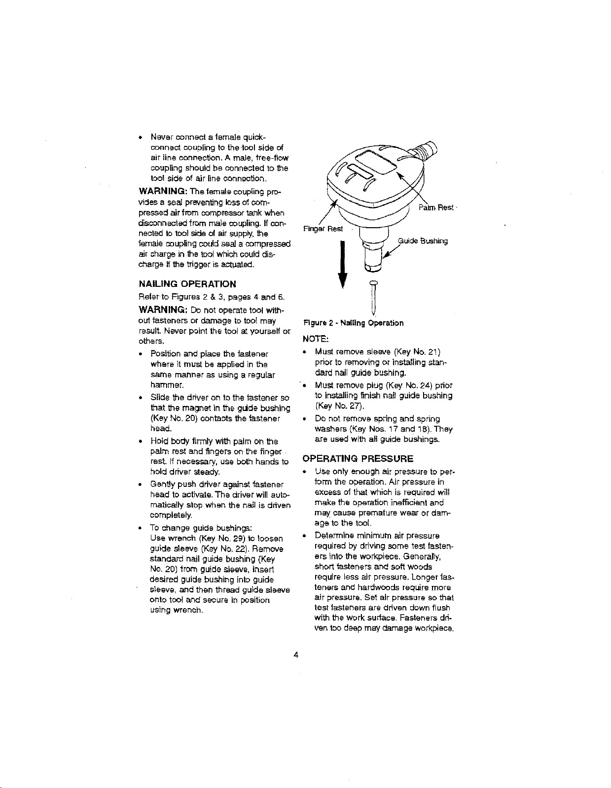
NAILING OPERATION
Retsr to Figures 2 & 3, pages 4 and 6.
WARNING; Do not operate tool with-
out fasteners or damage to too[ may
result. Never point the tool at yourself or
others.
Position and place the fastener
where it must be applied in the
same manner as using a regular
hammer.
Slide the driver on to the fastener so
that the magnet in the glide bushing
(Key No. 20) contants the fastener
head.
• Hold body firmly with palm on the
palm rest and fingers on the finger
rest. If necessary, use both hands to
hold driver steady.
Gently push driver againstfastener
head to activate. The driver wil! auto°
maritally stop when the na_ is driven
completely.
• To change guide bushings:
Use wrench {Key No. 29) to }oossn
guide sleeve (Key No. 22). Remove
standard nail guide bushing (Key
No. 20) from guide sleeve, insert
desired guide bushing into guide
sleeve, and then thread guide sleeve
onto toot and secure in position
using wrench.
_Rest
Finger Rest
w
GLiC'e_U_hing
Figure 2 - NailingOperation
NOTE:
Must remove sleeve (Key No. 2!)
prior to removing or installing stan-
dard nail guide bushing.
'o
Must remove plug (Key No.24-)prior
to installing finish nail guide bushing
(Key No. 27).
Do net remove spring and spring
washers (Key Nos. 17 and 18). They
are used with aE guide bushings.
OPERATING PRESSURE
Use only enough air pressure to per-
form the operation. Air pressure in
excess of that which is required will
make the operation inefficient and
may cause premature wear or dam-
age to the tool.
Determine minimum air pressure
required by driving some test fasten-
ers into the work;piece.Generally,
short fasteners and soft woods
require less air pressure. Longer fas-
teners and hardwoods require more
air pressure. Set air pressure so that
test fasteners are driven down flush
with the work surface. Fasteners dri-
ven too deep may damage workpiece.
 Loading...