

Craftsman 351181800 Owner’s Manual
Operator's Manual
3/4- 13/"Length
ROOFING NAILER
Model No.
351.1 81800
CAUTION: Read and follow
all Safety Rules and Operating
Instructions before First Use
of this Product. Keep this
manual with tool.
Sears, Roebuck and Co., Hoffman Estates, IL 60179 U.S.A.
www.sears.com/cra ftsman
21031.00 Draft (06/09/03)
• Safety
• Operation
• Maintenance
• Parts List
• EspaSol
Warranty ......................................... 2
Safety Rules...................................... 2
Operation ...................................... 3-6
Maintenance ..................................... 6
Troubleshooting ................................... 7
Parts Illustration and List .......................... 8-9
Espa£,ol...................................... 10-15
FULL ONE YEAR WARRANTY
Ifthis product fails due to a defect in material orworkmanship
within one year from the date of purchase, Sears will at its
option repair or replace it free of charge. Contact your nearest
Sears Service Center (1-800-4-MY-HOME) to arrange for
product repair, or return this product to place of purchase for
replacement.
If this product is used for commercial or rental purposes, this
warranty will apply for 90 days from the date of purchase.
This warranty applies only while this product is used inthe
United States.
This warranty gives you specific legal rights, and you may also
have other rights which vary from state to state.
Sears, Roebuck and Co., Dept. 817WA, Hoffman Estates,
IL 60179
Read and follow all safety rules and operating instructions
in this manual and on warning label of tool before using
this tool. Keep this manual with the tool.
• Keep work area clean and properly lighted.
• Keep children, bystanders and visitors at a safe distance
from work area while operating this tool.
• Air tool operators and all others in work area should
always wear safety goggles complying with United States
ANSI Z87.1 to prevent eye injury from fasteners and flying
debris when loading, operating and unloading this tool.
Everyday eyeglasses have only impact resistant lenses.
These are NOT safety glasses. ANSI Z67.1 safety glasses
have permanently attached rigid, hard plastic side shields
and will have "Z87.1" printed or stamped on them.
• Always wear ear protection. The work area may include
exposure to excessive noise levels which will require nec-
essary ear protection. Some environments will require
head protection; use head protection conforming to ANSI
Z89.1.
Do not alter or modify this tool in any way. Do not use this
tool for any application other than for which it was
designed.
Do not use oxygen, carbon dioxide, high-pressure com-
pressed gas or bottled gases as the power source for this
tool. The tool will explode and serious personal injury
could result.
• Never connectthe tool to air pressure which could poten-
tially exceed 200 psi. Use only clean, dry, regulated air
within rated range as marked on tool.
• The tool must have a male, free-flow hose coupling so that
all air pressure is removed from the tool when the coupling
joint is disconnected. Failure to use proper coupling could
cause accidental discharge, possibly causing injury.
• Only use air hose that is rated for a maximum working
pressure of 150 psi or 150% of the maximum system pres-
sure, whichever is greater.
• Do not use a hose swivel connector with this tool.
• Do not pull trigger or depress contact trip while connecting
to the air supply, as the tool may cycle, possibly causing
injury.
• When loading tool: Do not pull trigger or depress contact
trip; Do not point the tool at yourself or others; Do not
place hand or any part of body in the fastener discharge
area of the tool as accidental actuation may occur and
cause injury.
• Disconnect tool from air supply before loading or unload-
ing, performing tool maintenance, clearing a jammed fas-
tener, leaving work area, moving tool to another location or
handing the tool to another person.
• Use Sears recommended fasteners only.
• Do not load the tool until you are ready to use it.
• Always assume that the tool contains fasteners. Keep the
tool pointed away from yourself and others at all times.
Never engage in horseplay, Never pull the trigger unless
the contact trip is in contact with the workpiece. Keep oth-
ers at a safe distance from the tool while the tool is in
operation.
• Always remove finger from trigger when not driving fasten-
ers. Never carry the tool with finger on or under the trigger
as accidental actuation may occur and cause injury.
• Always keep hands and body away from the fastener dis-
charge area when air supply is connected to the tool. Grip
tool firmly to maintain control while allowing tool to recoil
away from work surface as fastener is driven. If contact trip
is allowed to recontact work surface before trigger is
released, an unwanted fastener may be driven.
• Check operation of the contact trip frequently. Never use
the tool if the contact trip, trigger or springs have become
inoperable, missing or damaged. Do not alter or remove
contact trip, trigger or springs. Never use a tool that is leak-
ing air, has missing or damaged parts, or requires repair.
• Do not drive fasteners on top of other fasteners or with the
tool at too steep an angle. The fasteners can ricochet and
cause injury. Do not drive fasteners close to the edge of
the workpiece. The workpiece is likely to split, allowing the
fastener to fly free and cause injury. Do not attempt to
drive fasteners into hard or brittle materials such as con-
crete, steel or tile.
• Do not overreach. Always place yourself in a firmly bal-
anced position when using or handling the tool. Do not
attach the hose or tool to your body.
• Do not operate tool without fasteners or damage to tool
may result.
• Do not use tool without safety warning label. If label is
missing, damaged or unreadable, contact SEARS to
obtain a new label.
• Only qualified repair personnel must perform tool service.
• When servicing a tool, use only identicalrepair parts.
• Store toolout of reach of children and other untrained
persons.
© Sears,Roebuckand Co.
2
DESCRIPTION
The Craftsman Roofing Nailer drives full size, full head roofing
nails from _/,"to 13/," long. Magazine holds 120 nails in a coil
so that one load will nail down one full bundle of shingles.Tool
can be used for new or reroofingwith either asphalt or fiber-
glass shingles. Safety feature disables tool unless contact trip
ispressed against workpiece. Depth adjuster controls depth
of fastener. Air deflector can be adjusted to any direction.The
contact trip is hardened to reduce wear caused by contact
with shingles. Die cast magnesium body withtexturedrubber
grip minimizes operator fatigue and makes nailer lightweight
and durable.
SPECIFICATIONS
Capacity ............................... 120 coil nails
Nail size ............................... 120" diameter
Nail lengths ................................ 3/_to 13/,"
Operating pressure ........................ 70-110 PSI
Air inlet ................................... '/," N.RT.
Length ....................................... 10'/_"
Height ....................................... 10W'
Width ........................................ 4¼6"
Weight ..................................... 4.2 Ibs.
NAILS
18413 ........ Galvanized roofing nails, 1" long x .120" dia.
18414 ....... Galvanized roofing nails,1_/4"long x .120" dia.
AIR SUPPLY LINE
Refer to Figure 1.
DANGER: Do not use oxygen, carbon dioxide, high-pressure
compressed gas or bottled gases as the power source for this
tool.The tool will explode and serious personal injurycould
result.
• The air tool operates on compressed air at pressures from
70to 110 PSI.
• Never connect the tool to air pressure which could poten-
tially exceed 200 PSI. Use only clean, dry, regulated air
within rated range as marked on tool.
Air Delivery Required: 2.0 SCFM @ 90 PSI
(30 shots per minute).
WARNING: Keep hands and body away from discharge area
of toolwhen connecting air supply.Always disconnecttool
from air supply when servicing oradjusting tooland when tool
is not in use.
• Air operated tools require clean, dry, lubricatedcom-
pressed air to ensure top performance, low maintenance
and long life.
• Dirt and abrasive materials present in all air lines will dam-
age tool O-rings, valves and cylinders.
• Moisture will reduce tool performance and life if not
removed from compressed air.
• A fUter-regulator-lubricator system is required and should be
located as close to tool as possible. A distance of less than
15 feet is recommended.
• Keep air filter clean. A dirty filter will reduce the air pressure
to the tool causing a reduction inpower and efficiency.
• The air supply system must be able to provide air pressure
of 70 to 110 pounds per square inchat tool.
• All hoses and pipes inthe air supply system must be clean
and free of moisture and foreign particles. Hoses must be
ratedfor a maximum working pressure of 150 PSI or 150%
of maximum system pressure, whichever is greater.
• Do not mountswivel connector in air supply line.
• The air pressure should be properly regulated.
• Different workpiece materials and differentfastener lengths
will requiredifferent operating pressure.
• Be sure all connectionsin air supply system are sealed to
prevent air loss.
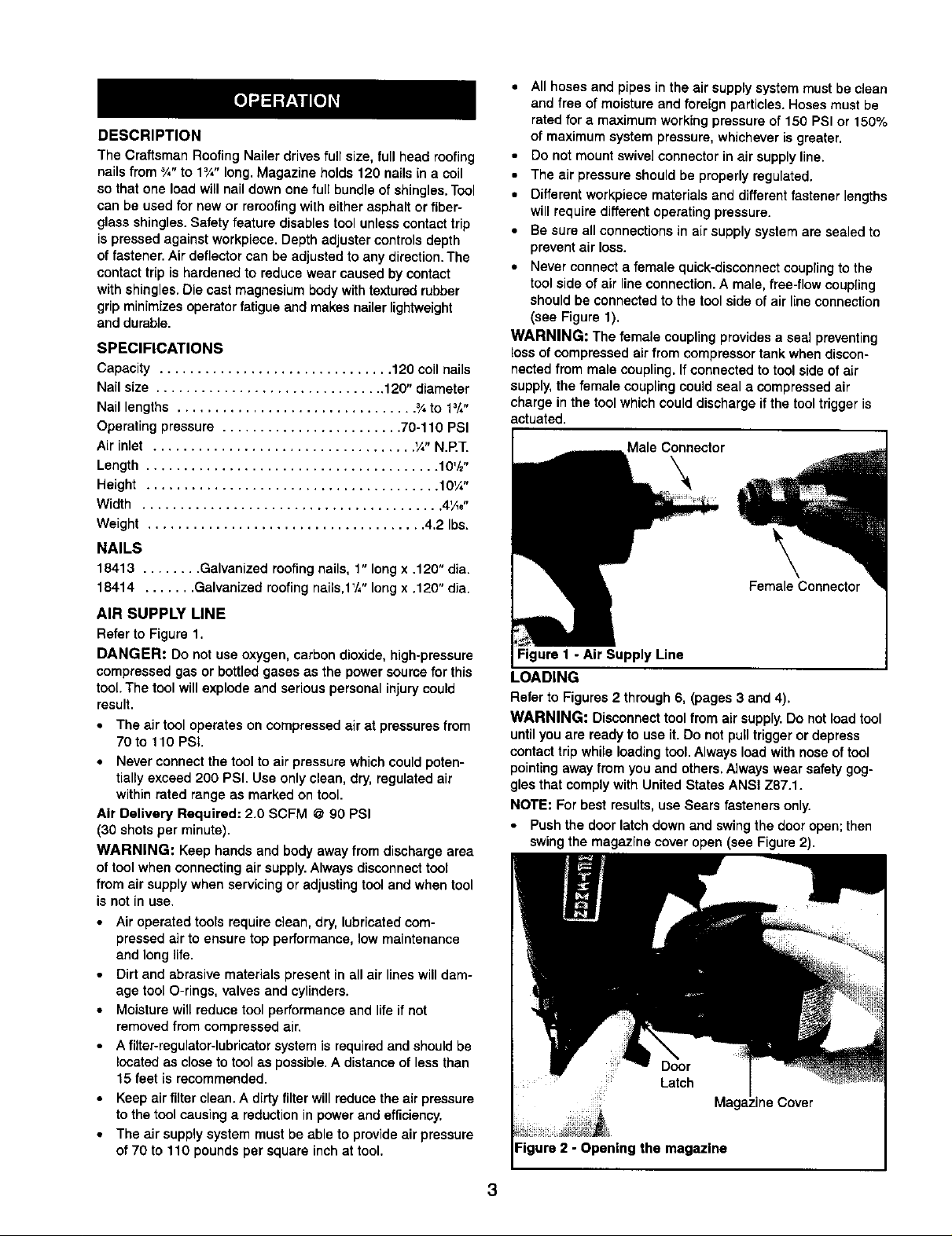
• Never connect a female quick-disconnect couplingto the
tool side of air line connection. A male, free-flow coupling
should be connected to the tool side ofair line connection
(see Figure 1).
WARNING: The female coupling provides a seal preventing
bossof compressed air from compressor tank when discon-
nected from male coupling. Ifconnected to tool side of air
supply,the female coupling couldseal a compressed air
charge in the tool which coulddischarge if the tooltrigger is
actuated.
Male Connector
\
Female Connector
Figure I - Air Supply Line
LOADING
Refer to Figures 2 through 6, (pages 3 and 4).
WARNING: Disconnect tool from air supply.Do not load tool
untilyou are ready to use it. Do not pull trigger or depress
contacttrip while loading tool. Always loadwith nose of tool
pointingaway from you and others. Always wear safety gog-
gles that comply with United States ANSI Z87.1.
NOTE: For best results, use Sears fasteners only.
Push the door latchdown and swingthe door open;then
swing the magazine cover open (see Figure 2).
Door
Latch
line Cover
Figure 2 - Opening the magazine
3
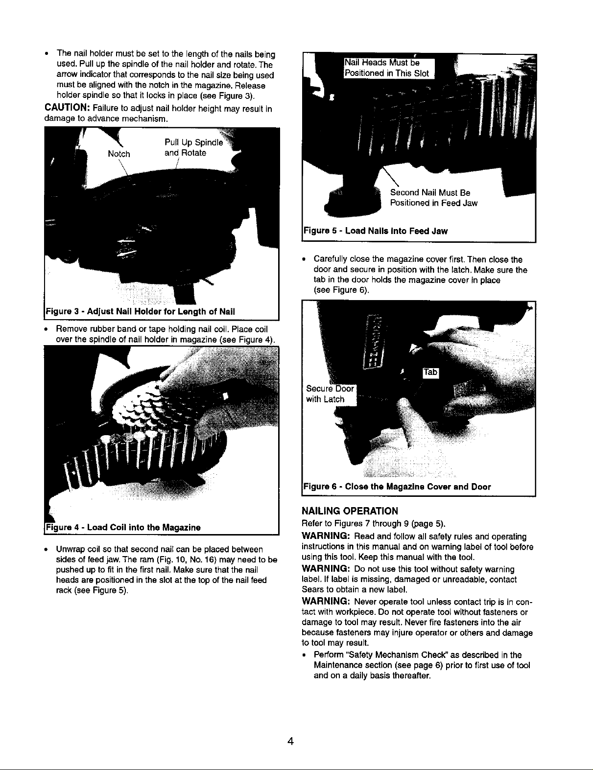
The nail holder must be set to the length of the nails being
used. Pull up the spindle of the nail holder and rotate. The
arrow indicator that corresponds to the nail size being used
must be aligned with the notch in the magazine. Release
holder spindle so that it locks in place (see Figure 3).
CAUTION: Failure to adjust nail holder height may result in
damage to advance mechanism.
Pull Up
ure 3 - Adjust Nail Holder for Length of Nail
• Remove rubber band or tape holdingnail coil. Place coil
over the spindle of nail holder in magazine (see Figure 4),
Second Nail Must Be
Positioned in Feed Jaw
Figure 5 - Load Nails Into Feed Jaw
• Carefully close the magazine cover first. Then close the
door and secure in position with the latch.Make sure the
tab in the door holds the magazine cover in place
(see Figure 6).
Figure 4 - Load Coil into the Magazine
Unwrap coil so that second nail can be placed between
sides of feed jaw. The ram (Fig. 10, No. 16) may need to be
pushed up to fit in the first nail. Make sure that the nail
heads are positioned in the slot at the top of the nail feed
rack (see Figure 5).
Figure 6 - Close the Magazine Cover and Door
NAILING OPERATION
Refer to Figures 7 through 9 (page 5).
WARNING: Read and follow all safety rules and operating
instructionsin this manual and on warning label of toolbefore
using this tool, Keep this manual with the tool.
WARNING: Do not use this tool withoutsafety warning
label, If label is missing,damaged or unreadable, contact
Sears to obtain a new label.
WARNING: Never operate tool unless contacttrip is incon-
tact with workpiece. Do not operate toolwithout fasteners or
damage to tool may result. Never fire fasteners intothe air
because fasteners may injure operator or othersand damage
to tool may result.
• Perform "Safety Mechanism Check" as described in the
Maintenance section (see page 6) priorto first usa of tool
and on a daily basis thereafter.
4
The air tool is equipped withcontact trip safety mechanism
that disables tool unless contact trip (Fig. 7) is pushed
against work. Hold body firmly and press contact trip on
workpiece where fastener is to be applied. Pull trigger to
drive fastener into workpiece.
The tool can also be operated by holding the trigger
depressed and pushing contact trip against workpiece.
This operating procedure provides rapid-fire fastener
driving. Never operate the tool unless contact trip is in
contact with workpiece.
OPERATING PRESSURE
• Use only enough air pressure to perform the operation. Air
pressure in excess of that which is required will make the
operation inefficient and may cause premature wear or
damage to the tool.
• Determine minimum air pressure required by driving some
test fasteners into the workpiece. Set air pressure so that
test fasteners are driven down flush with the work surface.
Fasteners driven too deep may damage workpiece.
WARNING: All air power fastening tools recoil when operat-
ed. This recoil is caused by rapid driving of the fastener. Tool
may bounce from recoil causing a second unwanted fastener
to be driven. Reduce tool bounce by holding tool firmly in
hand and pressing tool gently against workpiece. Let the tool
do the work.This will allow recoil of tool to bounce tool away
from workpiece preventing the driving of second fastener.
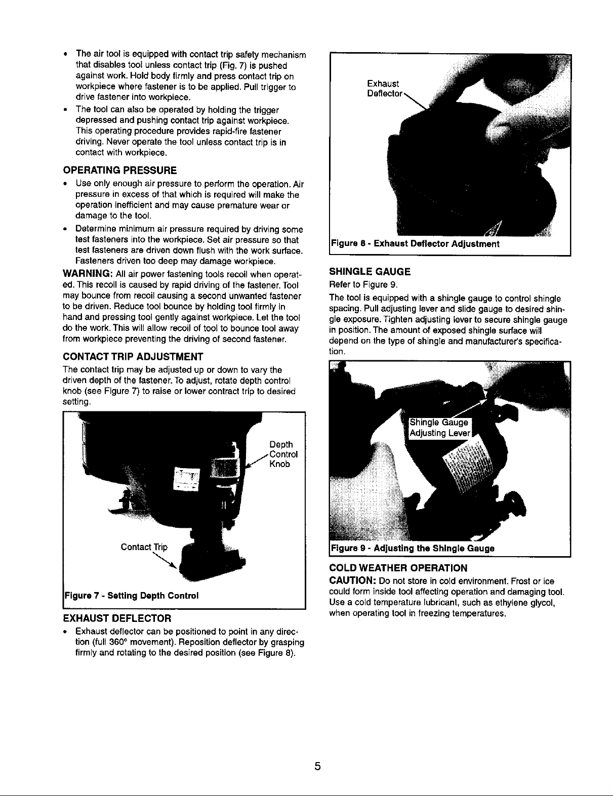
CONTACT TRIP ADJUSTMENT
The contact trip may be adjusted up or down to vary the
driven depth of the fastener. To adjust, rotate depth control
knob (see Figure 7) to raise or lower contract trip to desired
setting.
Exhaust
Deflector
Figure 8 - Exhaust Deflector Adjustment
SHINGLE GAUGE
Refer to Figure 9.
The tool isequipped with a shingle gauge to control shingle
spacing.Pull adjusting leverand slide gauge to desired shin-
gle exposure.Tighten adjusting lever to secure shingle gauge
in position.The amount of exposed shingle surfacewill
depend on the type of shingle and manufacturer's specifica-
tion.
Depth
Knob
Contact Trip
""-i
ure 7 - Setting Depth Control
EXHAUST DEFLECTOR
• Exhaust deflector can be positioned to point in any direc-
tion (full 360° movement). Reposition deflector by grasping
firmly and rotating to the desired position (see Figure 8).
Figure 9 - Adjusting the Shingle Gauge
COLD WEATHER OPERATION
CAUTION: Do not store in cold environment.Frostor ice
could form inside tool affecting operation and damaging tool.
Use a coldtemperature lubricant, such as ethylene glycol,
when operating toolin freezing temperatures.
5
 Loading...