

Operator's Manual
®
15 Gauge
11/,-21/2" Length
IN-LINE ANGLE FINISH NAILER
Model No.
351.181770
CAUTION: Read and follow
all Safety Rules and Operating
Instructions before First Use
of this Product. Keep this
manual with tool.
Sears, Roebuck and Co., Hoffman Estates, IL 60179 U.S.A.
www.sears.com/craftsman
21202.00 Draft (08/18/03)
• Safety
• Operation
• Maintenance
• Parts List
• EspaSol
Warranty ......................................... 2
Safety Rules ...................................... 2
Operation ...................................... 3-6
Maintenance ..................................... 6
Troubleshooting ................................... 7
Parts Illustration and List .......................... 8-9
Espa_ol ...................................... 10-16
FULL ONE YEAR WARRANTY
If this product fails due to a defect in material or workmanship
within one year from the date of purchase, Sears will at its
option repair or replace it free of charge. Contact your nearest
Sears Service Center (1-800-4-MY-HOME) to arrange for prod-
uct repair, or return this product to place of purchase for
replacement.
If this product is used for commercial or rental purposes, this
warranty will apply for 90 days from the date of purchase.
This warranty applies only while this product is used in the
United States.
This warranty gives you specific legal rights, and you may also
have other rights which vary from state to state.
Sears, Roebuck and Co., Dept. 817WA, Hoffman Estates,
IL 60179
• Read and follow all safety rules and operating instructions
in this manual and on warning label of tool before using
this tool. Keep this manual with the tool.
• Keep work area clean and properly lighted.
• Keep children, bystanders and visitors at a safe distance
from work area while operating this tool.
• Air tool operators and all others in work area should
always wear safety goggles complying with United States
ANSI Z87.1 to prevent eye injury from fasteners and flying
debris when loading, operating and unloading this tool.
Everyday eyeglasses have only impact resistant lenses.
These are NOT safety glasses. ANSI Z87.1 safety glasses
have permanently attached rigid, hard plastic side shields
and will have "Z87.1" printed or stamped on them.
• Always wear ear protection. The work area may include
exposure to excessive noise levels which will require nec-
essary ear protection. Some environments will require
head protection; use head protection conforming to ANSI
Z89.1.
• Do not alter or modify this tool in any way. Do not use this
tool for any application other than for which it was
designed.
• Do not use oxygen, carbon dioxide, high-pressure com-
pressed gas or bottled gases as the power source for this
tool. The tool will explode and serious personal injury
could result.
• Never connect the tool to air pressure which could poten-
tially exceed 200 psi. Use only clean, dry, regulated air
within rated range as marked on tool.
• The tool must have a male, free-flow hose coupling so that
all air pressure is removed from the tool when the coupling
joint is disconnected. Failure to use proper coupling could
cause accidental discharge, possibly causing injury.
• Only use air hose that is rated for a maximum working
pressure of 150 psi or 150% of the maximum system pres-
sure, whichever is greater.
• Do not use a hose swivel connector with this tool.
• Do not pull trigger or depress contact trip while connecting
to the air supply, as the tool may cycle, possibly causing
injury.
• When loading tool: Do not pull trigger or depress contact
trip; Do not point the tool at yourself or others; Do not
place hand or any part of body in the fastener discharge
area of the tool as accidental actuation may occur and
cause injury.
,, Disconnect tool from air supply before loading or unload-
ing, performing tool maintenance, clearing a jammed fas-
tener, leaving work area, moving tool to another location or
handing the tool to another person.
• Use Sears recommended fasteners only.
• Do not load the tool until you are ready to use it.
• Always assume that the tool contains fasteners. Keep the
tool pointed away from yourself and others at all times.
Never engage in horseplay. Never pull the trigger unless
the contact trip is in contact with the workpiece. Keep oth-
ers at a safe distance from the tool while the tool is in
operation.
• Always remove finger from trigger when not driving fasten-
ers. Never carry the tool with finger on or under the trigger
as accidental actuation may occur and cause injury.
• Always keep hands and body away from the fastener dis-
charge area when air supply is connected to the tool. Grip
tool firmly to maintain control while allowing tool to recoil
away from work surface as fastener is driven. If contact trip
is allowed to recontact work surface before trigger is
released, an unwanted fastener may be driven.
• Check operation of the contact trip frequently. Never use
the tool if the contact trip, trigger or springs have become
inoperable, missing or damaged. Do not alter or remove
contact trip, trigger or springs. Never use a tool that is leak-
ing air, has missing or damaged parts, or requires repair.
• Do not drive fasteners on top of other fasteners or with the
tool at too steep an angle. The fasteners can ricochet and
cause injury. Do not drive fasteners close to the edge of
the workpiece. The workpiece is likely to split, allowing the
fastener to fly free and cause injury. Do not attempt to
drive fasteners into hard or brittle materials such as con-
crete, steel or tile.
• Do not overreach. Always place yourself in a firmly bal-
anced position when using or handling the tool. Do not
attach the hose or tool to your body.
• Do not operate tool without fasteners or damage to tool
may result.
• Do not use tool without safety warning label. If label is
missing, damaged or unreadable, contact SEARS to
obtain a new label.
• Only qualified repair personnel must perform tool service.
• When servicing a tool, use only identical repair parts.
• Store tool out of reach of children and other untrained
persons.
@Sears, Roebuck and Co. 2
DESCRIPTION
The Craftsman 15 Gauge In-line Angle Finish Nailer drives
nails from 1%" to 2%" long. Magazine is angled at 32 ° for nail-
ing in tight spots. Lightweight cast magnesium body with tex-
tured finish and professional cushioned grip minimizes operator
fatigue. Large capacity, rear loading magazine makes loading
easy. Safety feature disables tool unless contact trip is pressed
against workpiece. Tapered nosepiece provides operator with
greater visibility for precise fastener placement. Quick release
nose cover allows easy access to jammed fasteners.
Adjustment knob controls depth of fastener. Air deflector can be
adjusted to any direction. The 15 Gauge Finish Nailer is
excellent for interior and exterior trim work, door and window
manufacturing, furniture making and cabinetry.
SPECIFICATIONS
Capacity .............................. 100 finish nails
Nail diameter ................. 15 Gauge (.068" to .072")
Nail lengths ............................... 1_/4to 2W'
Operating pressure ...................... 70 to 110 PSI
Air inlet .................................... W' N.RT.
Length ....................................... 13W'
Height ........................................ 12W'
Width ......................................... 3W'
Weight ..................................... 4.4 Ibs.
FINISH NAILS
18348 (Box of 4000) ........ 15 gauge finish nails, 1_/2'' long
19193 (Box of 1000) ........ 15 gauge finish nails, 1W' long
18349 (Box of 4000) ......... 15 gauge finish nails, 2" long
19194 (Box of 1000) ......... 15 gauge finish nails, 2" long
18355 (Box of 3000) ........ 15 gauge finish nails, 2W' long
19195 (Box of 1000) ........ 15 gauge finish nails, 2W' long
AIR SUPPLY LINE
Refer to Figure 1.
DANGER: Do not use oxygen, carbon dioxide, high-pressure
compressed gas or bottled gases as the power source for this
tool. The tool will explode and serious personal injury could
result.
• The air tool operates on compressed air at pressures from
70 to 110 PSI.
• Never connect the tool to air pressure which could poten-
tially exceed 200 PSI. Use only clean, dry, regulated air
within rated range as marked on tool.
Air Delivery Required: 1.41 SCFM @ 90 PSI
(30 shots per minute).
WARNING: Keep hands and body away from discharge area
of tool when connecting air supply. Always disconnect tool
from air supply when servicing or adjusting tool and when tool
is not in use.
• Air operated tools require clean, dry, lubricated com-
pressed air to ensure top performance, low maintenance
and long life.
• Dirt and abrasive materials present in all air lines will dam-
age tool O-rings, valves and cylinders.
• Moisture will reduce tool performance and life if not
removed from compressed air.
,, A filter-regulator-lubricator system is required and should be
located as close to tool as possible. A distance of less than
15 feet is recommended. Lubricator is not required for
oilless tools.
,, Keep air filter clean. A dirty filter will reduce the air pressure
to the tool causing a reduction in power and efficiency.
,, The air supply system must be able to provide air pressure
of 70 to 110 pounds per square inch at tool.
,, All hoses and pipes in the air supply system must be clean
and free of moisture and foreign particles. Hoses must be
rated for a maximum working pressure of 150 PSi or 150%
of maximum system pressure, whichever is greater.
,, Do not mount swivel connector in air supply line.
,, The air pressure should be properly regulated.
,, Different workpiece materials and different fastener lengths
will require different operating pressure.
,, Be sure all connections in air supply system are sealed to
prevent air loss.
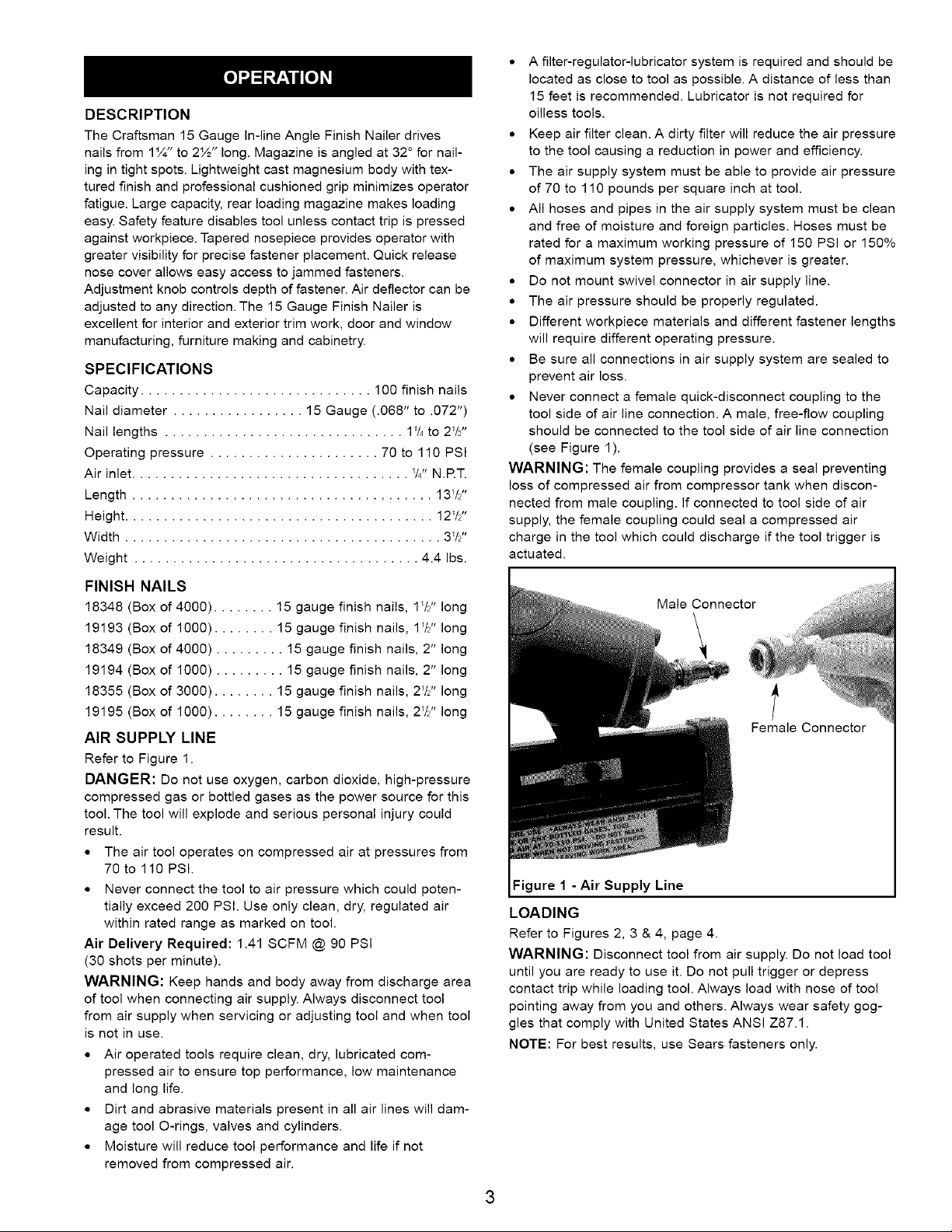
,, Never connect a female quick-disconnect coupling to the
tool side of air line connection. A male, free-flow coupling
should be connected to the tool side of air line connection
(see Figure 1).
WARNING: The female coupling provides a seal preventing
loss of compressed air from compressor tank when discon-
nected from male coupling. If connected to tool side of air
supply, the female coupling could seal a compressed air
charge in the tool which could discharge if the tool trigger is
actuated.
Male Connector
\
t
Female Connector
Figure I - Air Supply Line
LOADING
Refer to Figures 2, 3 & 4, page 4.
WARNING: Disconnect tool from air supply. Do not load tool
until you are ready to use it. Do not pull trigger or depress
contact trip while loading tool. Always load with nose of tool
pointing away from you and others. Always wear safety gog-
gles that comply with United States ANSI Z87.1.
NOTE: For best results, use Sears fasteners only.
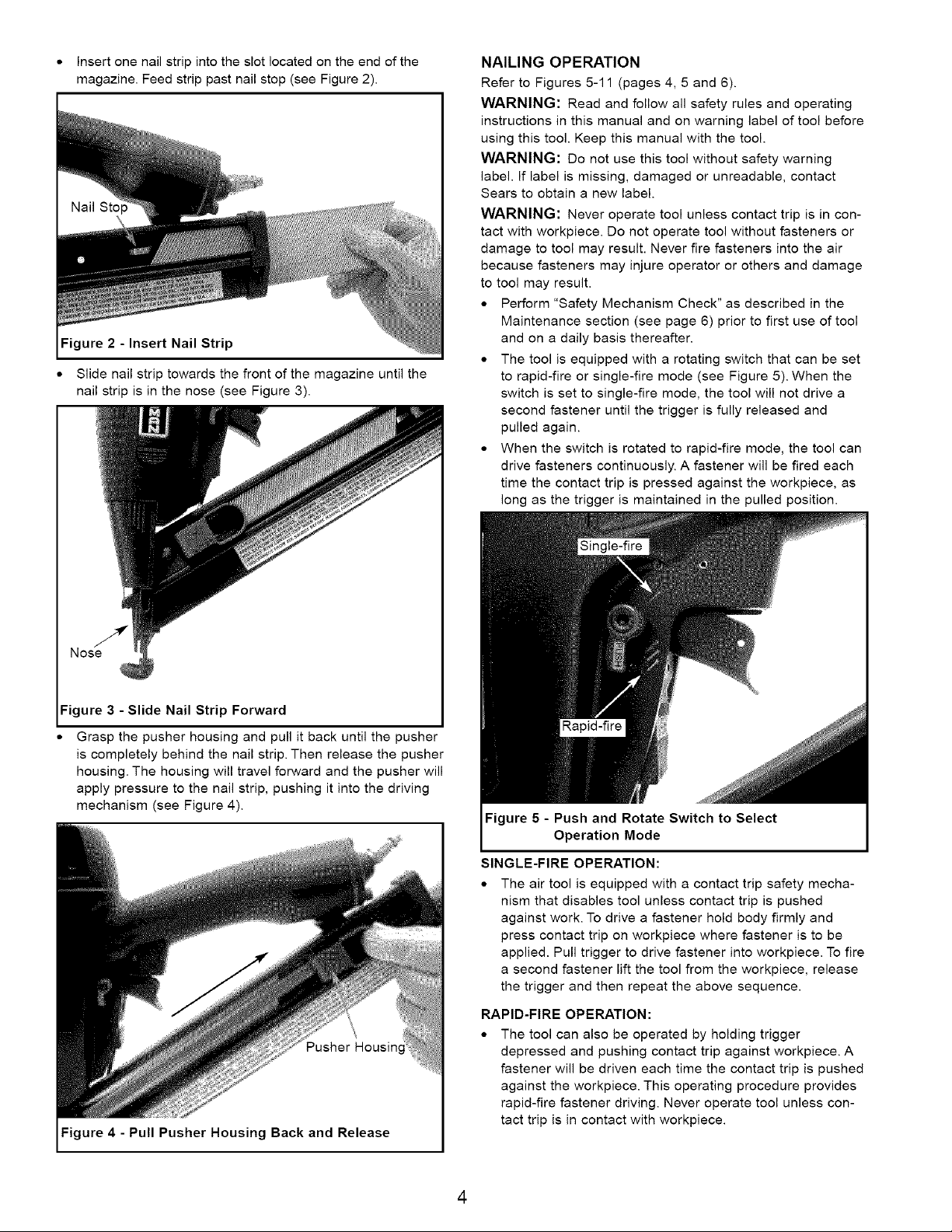
* Insertonenailstripintotheslotlocatedontheendofthe
magazine.Feedstrippastnailstop(seeFigure2).
ure 2 - Insert Nail Strip
• Slide nail strip towards the front of the magazine until the
nail strip is in the nose (see Figure 3).
NAILING OPERATION
Refer to Figures 5-11 (pages 4, 5 and 6).
WARNING: Read and follow all safety rules and operating
instructions in this manual and on warning label of tool before
using this tool. Keep this manual with the tool.
WARNING: Do not use this tool without safety warning
label. If label is missing, damaged or unreadable, contact
Sears to obtain a new label.
WARNING: Never operate tool unless contact trip is in con-
tact with workpiece. Do not operate tool without fasteners or
damage to tool may result. Never fire fasteners into the air
because fasteners may injure operator or others and damage
to tool may result.
• Perform "Safety Mechanism Check" as described in the
Maintenance section (see page 6) prior to first use of tool
and on a daily basis thereafter.
• The tool is equipped with a rotating switch that can be set
to rapid-fire or single-fire mode (see Figure 5). When the
switch is set to single-fire mode, the tool will not drive a
second fastener until the trigger is fully released and
pulled again.
• When the switch is rotated to rapid-fire mode, the tool can
drive fasteners continuously. A fastener will be fired each
time the contact trip is pressed against the workpiece, as
long as the trigger is maintained in the pulled position.
Figure 3 - Slide Nail Strip Forward
Grasp the pusher housing and pull it back until the pusher
is completely behind the nail strip. Then release the pusher
housing. The housing will travel forward and the pusher will
apply pressure to the nail strip, pushing it into the driving
mechanism (see Figure 4).
Pusher
Figure 4 - Pull Pusher Housing Back and Release
Figure 5 - Push and Rotate Switch to Select
Operation Mode
SINGLE-FIRE OPERATION:
• The air tool is equipped with a contact trip safety mecha-
nism that disables tool unless contact trip is pushed
against work. To drive a fastener hold body firmly and
press contact trip on workpiece where fastener is to be
applied. Pull trigger to drive fastener into workpiece. To fire
a second fastener lift the tool from the workpiece, release
the trigger and then repeat the above sequence.
RAPID-FIRE OPERATION:
• The tool can also be operated by holding trigger
depressed and pushing contact trip against workpiece. A
fastener will be driven each time the contact trip is pushed
against the workpiece. This operating procedure provides
rapid-fire fastener driving. Never operate tool unless con-
tact trip is in contact with workpiece.
4
WARNING: All air power fastening tools recoil when operat-
ed. This recoil is caused by rapid driving of the fastener. Tool
may bounce from recoil causing a second unwanted fastener
to be driven. Reduce tool bounce by holding tool firmly in
hand and pressing tool gently against workpiece. Let the tool
do the work. This will allow recoil of tool to bounce tool away
from workpiece preventing the driving of second fastener.
CONTACT TRIP ADJUSTMENT
The contact trip may be adjusted up or down to vary the
depth of the fastener in the workpiece. To adjust, rotate depth
control knob (see Figure 6) to raise or lower contract trip to
desired setting.
Depth
Control
Knob
Figure 6 - Setting Depth Control
CONTACT TRIP PAD
The tool is equipped with a contact trip pad (see Figure 7)
that prevents marring of finished surfaces by the contact trip
during normal operation.
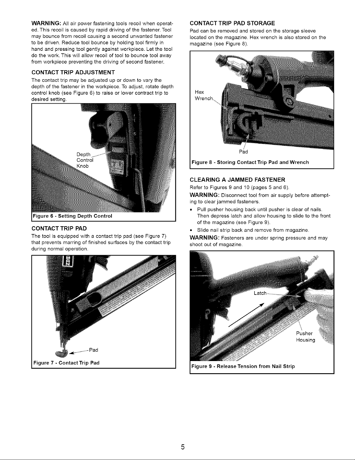
CONTACT TRIP PAD STORAGE
Pad can be removed and stored on the storage sleeve
located on the magazine. Hex wrench is also stored on the
magazine (see Figure 8).
Hex
Wrench
/
Pad
Figure 8 - Storing Contact Trip Pad and Wrench
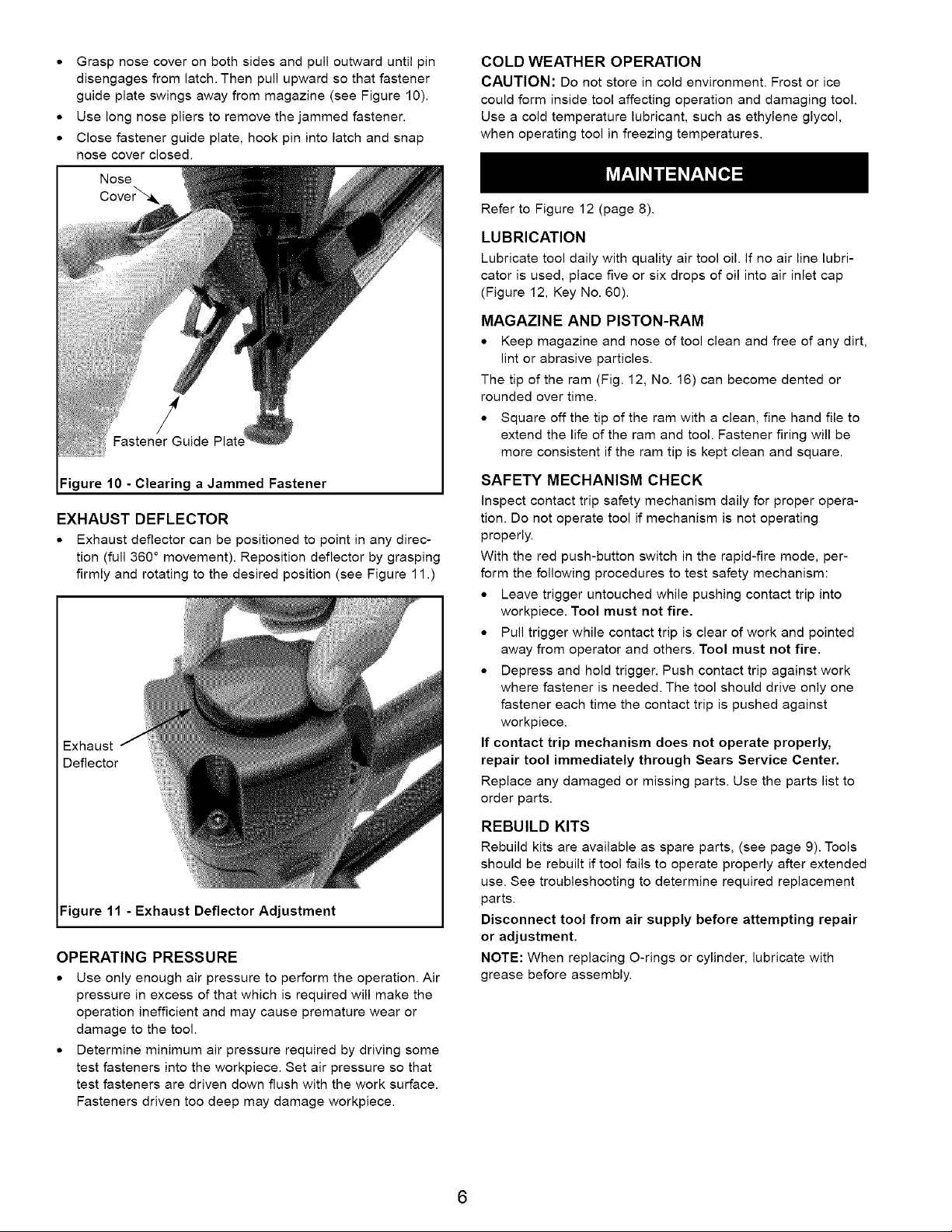
CLEARING A JAMMED FASTENER
Refer to Figures 9 and 10 (pages 5 and 6).
WARNING: Disconnect tool from air supply before attempt-
ing to clear jammed fasteners.
• Pull pusher housing back until pusher is clear of nails.
Then depress latch and allow housing to slide to the front
of the magazine (see Figure 9).
• Slide nail strip back and remove from magazine.
WARNING: Fasteners are under spring pressure and may
shoot out of magazine.
Figure 7 - Contact Trip Pad
Pusher
Housing
Figure 9 - Release Tension from Nail Strip
• Graspnosecoveronbothsidesandpulloutwarduntilpin
disengagesfromlatch.Thenpullupwardsothatfastener
guideplateswingsawayfrommagazine(seeFigure10).
• Uselongnoseplierstoremovethejammedfastener.
• Closefastenerguideplate,hookpinintolatchandsnap
nosecoverclosed.
Nose
/
Fastener Guide
COLD WEATHER OPERATION
CAUTION: Do not store in cold environment. Frost or ice
could form inside tool affecting operation and damaging tool.
Use a cold temperature lubricant, such as ethylene glycol,
when operating tool in freezing temperatures.
Refer to Figure 12 (page 8).
LUBRICATION
Lubricate tool daily with quality air tool oil. If no air line lubri-
cator is used, place five or six drops of oil into air inlet cap
(Figure 12, Key No. 60).
MAGAZINE AND PISTON-RAM
• Keep magazine and nose of tool clean and free of any dirt,
lint or abrasive particles.
The tip of the ram (Fig. 12, No. 16) can become dented or
rounded over time.
• Square off the tip of the ram with a clean, fine hand file to
extend the life of the ram and tool. Fastener firing will be
more consistent if the ram tip is kept clean and square.
Figure 10 -Clearing a Jammed Fastener
EXHAUST DEFLECTOR
• Exhaust deflector can be positioned to point in any direc-
tion (full 360 ° movement). Reposition deflector by grasping
firmly and rotating to the desired position (see Figure 11.)
Exhaust
Deflector
Figure 11 - Exhaust Deflector Adjustment
OPERATING PRESSURE
• Use only enough air pressure to perform the operation. Air
pressure in excess of that which is required will make the
operation inefficient and may cause premature wear or
damage to the tool.
• Determine minimum air pressure required by driving some
test fasteners into the workpiece. Set air pressure so that
test fasteners are driven down flush with the work surface.
Fasteners driven too deep may damage workpiece.
SAFETY MECHANISM CHECK
inspect contact trip safety mechanism daily for proper opera-
tion. Do not operate tool if mechanism is not operating
properly.
With the red push-button switch in the rapid-fire mode, per-
form the following procedures to test safety mechanism:
• Leave trigger untouched while pushing contact trip into
workpiece. Tool must not fire.
• Pull trigger while contact trip is clear of work and pointed
away from operator and others. Tool must not fire.
• Depress and hold trigger. Push contact trip against work
where fastener is needed. The tool should drive only one
fastener each time the contact trip is pushed against
workpiece.
If contact trip mechanism does not operate properly,
repair tool immediately through Sears Service Center.
Replace any damaged or missing parts. Use the parts list to
order parts.
REBUILD KITS
Rebuild kits are available as spare parts, (see page 9). Tools
should be rebuilt if tool fails to operate properly after extended
use. See troubleshooting to determine required replacement
parts.
Disconnect tool from air supply before attempting repair
or adjustment.
NOTE: When replacing O-rings or cylinder, lubricate with
grease before assembly.
6
 Loading...