

Craftsman 33668 Operator's Manual
OPERATOR'S MANUAL
RRrrSMRN
HOMEOWNER'S SERIES -INTERMEDIATE
MODEL # 33668
CALL 1=800=833=4405 FOR SERVICE PARTS. Refer to Service
Parts Drawing for full listing of Service Parts.
LOCATING MODEL # iNFORMATiON
Model numbers and other information required for service parts is
located on a label on the interior right side of the top most drawer.
• The maximum weight for each drawer should be no more than
25 pounds.
• Empty weight of the unit is 33 Ibs.
• The maximum product weight, including contents, should be no
more than 125 pounds.
• For casters, use high quality bearing grease, (yearly).
• Lubricate the slides with grease or equivalent,(twice yearly.)
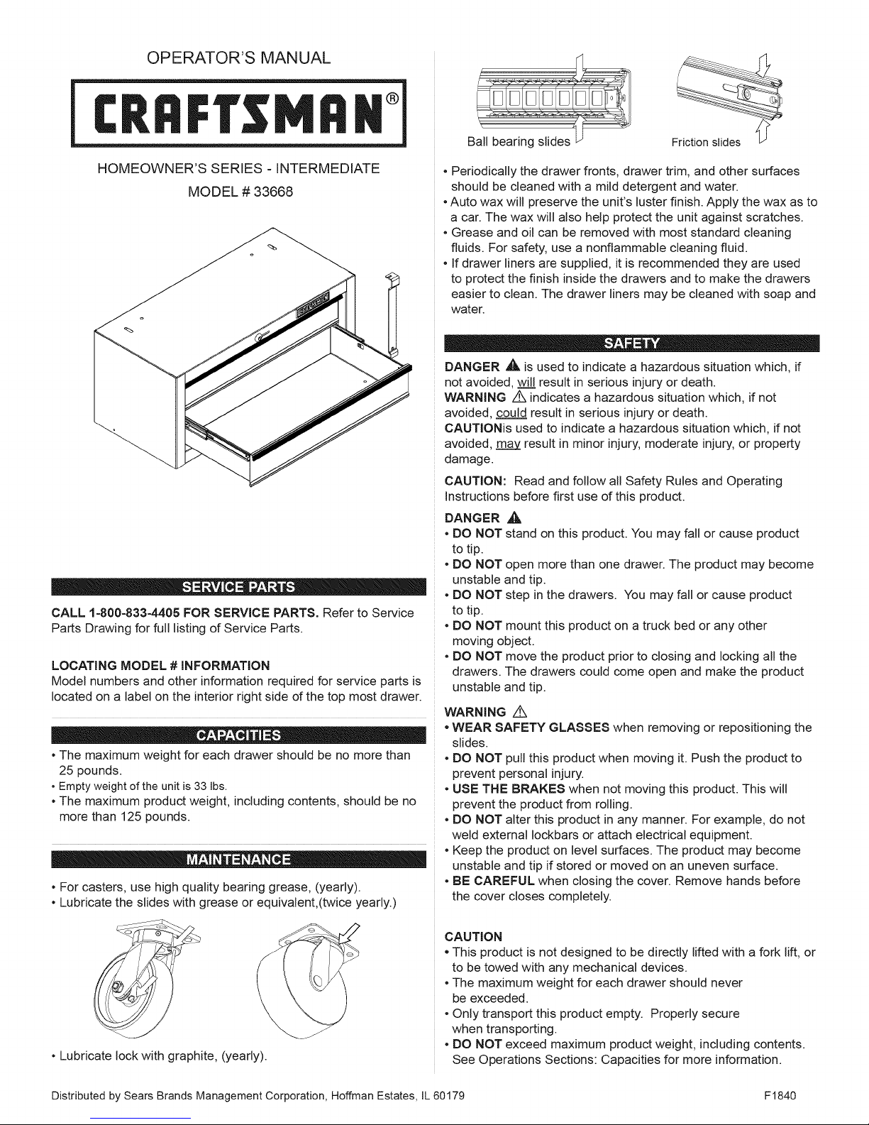
Ball bearing slides
• Periodically the drawer fronts, drawer trim, and other surfaces
should be cleaned with a mild detergent and water.
• Auto wax will preserve the unit's luster finish. Apply the wax as to
a car. The wax will also help protect the unit against scratches.
• Grease and oil can be removed with most standard cleaning
fluids. For safety, use a nonflammable cleaning fluid.
• If drawer liners are supplied, it is recommended they are used
to protect the finish inside the drawers and to make the drawers
easier to clean. The drawer liners may be cleaned with soap and
water.
DANGER _L. is used to indicate a hazardous situation which, if
not avoided, will result in serious injury or death.
WARNING Z_ indicates a hazardous situation which, if not
avoided, could result in serious injury or death.
CAUTIONis used to indicate a hazardous situation which, if not
avoided, may result in minor injury, moderate injury, or property
damage.
CAUTION: Read and follow all Safety Rules and Operating
instructions before first use of this product.
DANGER
• DO NOT
to tip.
• DO NOT
unstable
• DO NOT
to tip.
• DO NOT mount this product on a truck bed or any other
moving object.
• DO NOT move the product prior to closing and locking all the
drawers. The drawers could come open and make the product
unstable and tip.
WARNING Z_
• WEAR SAFETY GLASSES when removing or repositioning the
slides.
• DO NOT pull this product when moving it. Push the product to
prevent personal injury.
• USE THE BRAKES when not moving this product. This will
prevent the product from roiling.
• DO NOT alter this product in any manner. For example, do not
weld external Iockbars or attach electrical equipment.
• Keep the product on level surfaces. The product may become
unstable and tip if stored or moved on an uneven surface.
• BE CAREFUL when closing the cover. Remove hands before
the cover closes completely.
A
stand on this product. You may fall or cause product
open more than one drawer. The product may become
and tip.
step inthe drawers. You may fall or cause product
Friction slides /L_
• Lubricate lock with graphite, (yearly).
Distributed by Sears Brands Management Corporation, Hoffman Estates, JL60179 F1840
CAUTION
• This product is not designed to be directly lifted with a fork lift, or
to be towed with any mechanical devices.
• The maximum weight for each drawer should never
be exceeded.
• Only transport this product empty. Properly secure
when transporting.
• DO NOT exceed maximum product weight, including contents.
See Operations Sections: Capacities for more information.
Tools Required:
3/8 inch wrench
5/16-inch drill bit
HARDWARE INCLUDED:
1/4 - 20 x 5/8-in (Qty: 4)
1/4- 20 Nut (Qty: 4)
NOTE: Not all operation instructions will relate to your model.
TO LOCK iNTERMEDiATE CHEST
The Iockbar for the intermediate chest is stored in the
top drawer.
Process:
- Insert the Iockbar into the slot in the base.
- Move the Iockbar toward the unit until the bent end fits
into the slot near the lock.
- Lock with the key.
TO UNLOCK INTERMEDIATE CHEST
- Reverse above procedure.
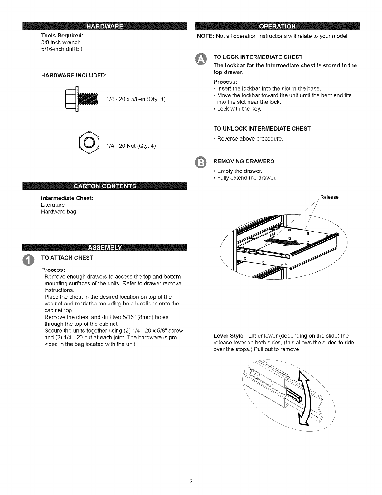
REMOVING DRAWERS
• Empty the drawer.
• Fully extend the drawer.
Intermediate Chest:
Literature
Hardware bag
TO ATTACH CHEST
Process:
• Remove enough drawers to access the top and bottom
mounting surfaces of the units. Refer to drawer removal
instructions.
• Place the chest in the desired location on top of the
cabinet and mark the mounting hole locations onto the
cabinet top.
• Remove the chest and drill two 5/16" (8mm) holes
through the top of the cabinet.
• Secure the units together using (2) 1/4 - 20 x 5/8" screw
and (2) 1/4 - 20 nut at each joint. The hardware is pro-
vided in the bag located with the unit.
Release
Lever Style - Lift or lower (depending on the slide) the
release lever on both sides, (this allows the slides to ride
over the stops.) Pull out to remove.
Tab Style - Depress the release tabs on both sides,
(this allows the slides to ride over the stops.) Pull out to
remove.
Friction Style - Fully extend the drawer. Insert screwdriver
into the slot in the side and push in on the stop until it
clears the lance. Pull drawer just past lance before releas-
ing stop. Repeat the process for the other slide.
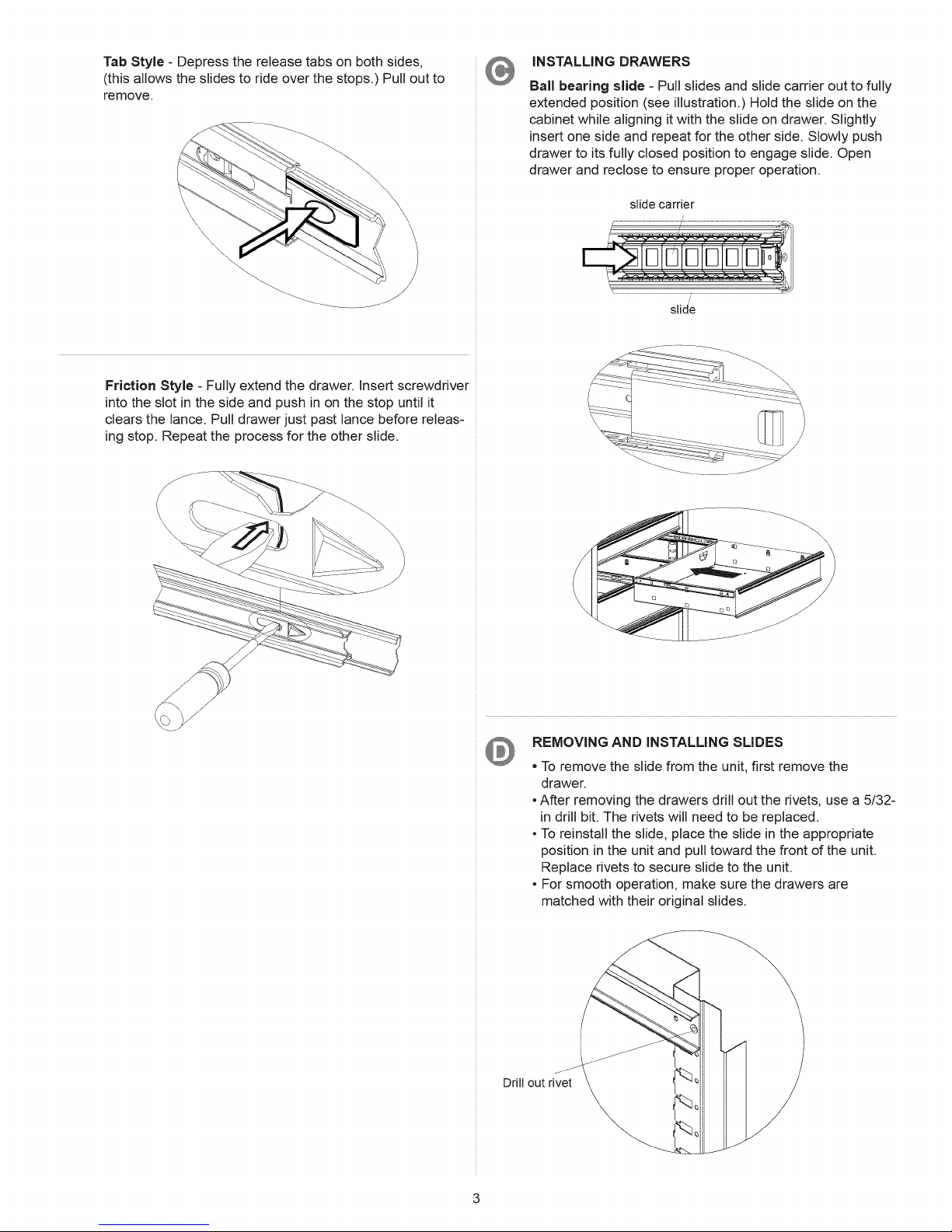
iNSTALLING DRAWERS
Ball bearing slide - Pull slides and slide carrier out to fully
extended position (see illustration.) Hold the slide on the
cabinet while aligning it with the slide on drawer. Slightly
insert one side and repeat for the other side. Slowly push
drawer to its fully closed position to engage slide. Open
drawer and reclose to ensure proper operation.
slidecarrier
/
slide
- ---__ ............
REMOVING AND iNSTALLING SLIDES
To remove the slide from the unit, first remove the
drawer.
• After removing the drawers drill out the rivets, use a 5/32-
in drill bit. The rivets will need to be replaced.
• To reinstall the slide, place the slide in the appropriate
position in the unit and pull toward the front of the unit.
Replace rivets to secure slide to the unit.
• For smooth operation, make sure the drawers are
matched with their original slides.
\
Drill out rivet
\
\
/
 Loading...