

Craftsman 333170 Operator's Manual
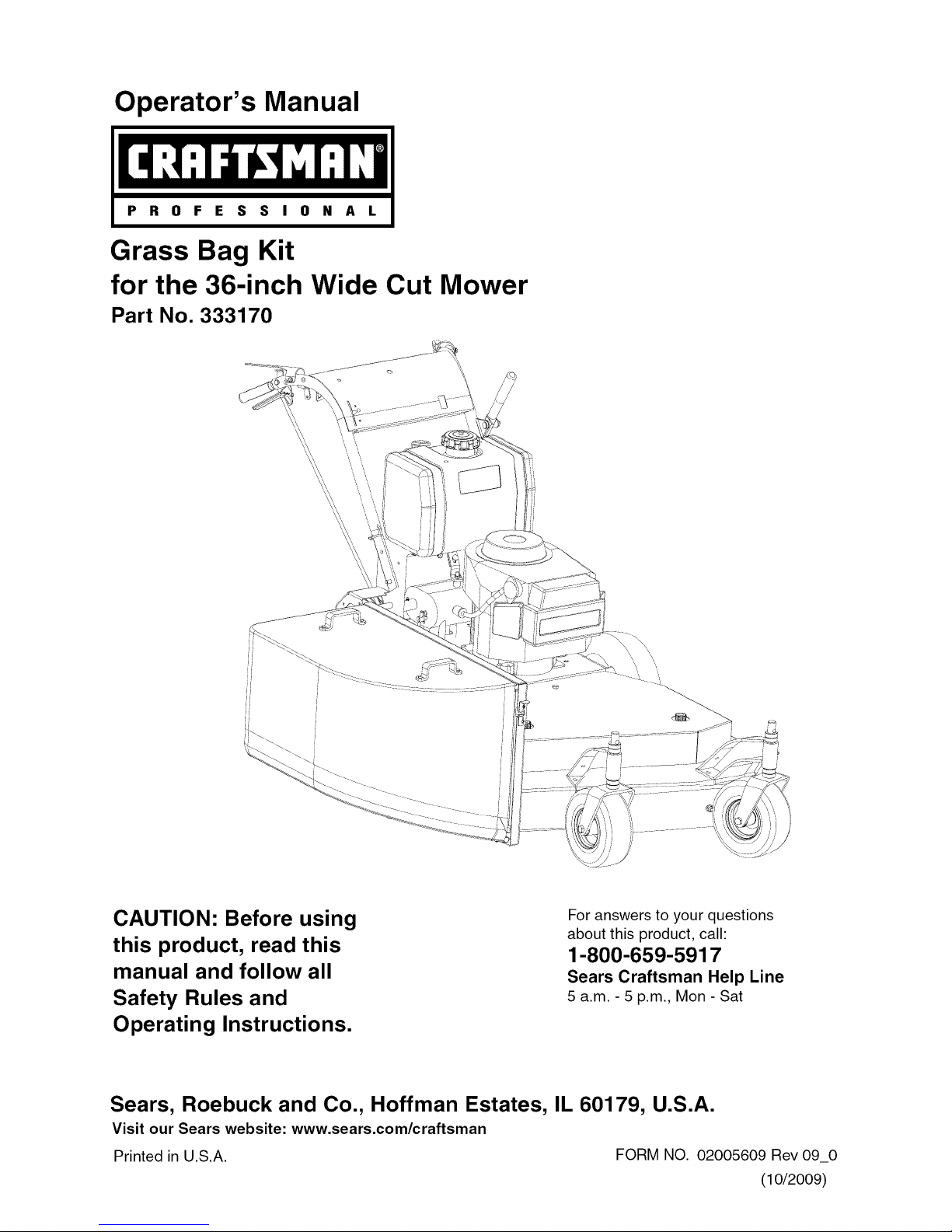
Operator's Manual
Grass Bag Kit
for the 36-inch Wide Cut Mower
Part No. 333170
CAUTION: Before using
this product, read this
manual and follow all
Safety Rules and
Operating Instructions.
Sears, Roebuck and Co., Hoffman Estates, IL 60179, U.S.A.
Visit our Sears website: www.sears.com/craftsman
Printed in U.S.A. FORM NO. 02005609 Rev 09_0
For answers to your questions
about this product, call:
1-800-659-5917
Sears Craftsman Help Line
5 a.m. - 5 p.m., Mon - Sat
(10/2009)
AssemblyandOperation 2
EspaSol 8
ServiceNumbers BackCover
WARNING: Before installing this accessory, shut the engine off and allow it to cool. Disconnect the
spark plug wire from the spark plug. Refer to the mower's Operator's Manual for complete safety
instructions. Do not operate the mower without the entire grass bag in place. Turn the mower off and
disconnect the spark plug before emptying the grass bag.
CARTONCONTENTS
Before installing this accessory, remove all parts from the carton. Use caution when handling parts, some metal
parts may have sharp edges. Carton contents, including items included within the hardware pack, are shown in
Figures 1 and 2 on page 3. Part numbers are shown in parentheses and each item has been identified with a letter
code, [X], for use when following the assembly instructions. Reference to right or left side of the mower is observed
from the operating position.
TOOLSREQUIRED
Two 9/16" wrenches. Two 7/16" wrenches. One 3/8" wrench. One Flat Blade and One Phillips screwdriver.
[D]LeftLatch
(703-06695)
[F]BackingPlate
(703-06692)
• ii
[E]RightLatch
(703-06694)
[B]BagFrame
(01003986)
[C]Handles
(703-06696)
[S] Chute Baffle
(02005727)
Figure 1
[K] 1/4-20 x 1.00
Qty. 4
(01000944)
[I] Internal Tooth.
Washers Qty. 4
(02005631)
[L] 1/4-20 Nylock ......
nuts Qty. 4 __)
00012152)
Latch Hardware
M] 10-32 x 5/8_ _
Pan Head Screws
Qty. 4 (00030906)
[N] 10-32 Nylock-''l_
nuts Qty. 4
(00014608)
Figure 2
_ j
[G] Cute Mounting Bracket
(703-06693)
Handle Hardware
[0] 3/8-16 X 1.25_ _-Z_
Qty. 2 (00011444) i
[R] 3/8-16 Nylock
nuts Qty. 2
(00012173)
[A] Struts
Chute Bracket to
Backing Plate
[P] 3/8-16 X 1.00 ......._-r:
Qty. 2
(00012171)
[Q] 3/8 Flat -_DP'L,, _-j/i
Washers Qty. 4
(01000723)
[R] 3/8-16 Nylock
nuts Qty. 2
(00012173)
-[j
/ (f % ';
, x j /
Chute Bracket
to Mower
'\ . J
/
[H] Cloth Bag
(01003221)
Chute Baffle
to Mower
[T] 5/16-18 X "-'----tb_
1.00 Qty. 1
(00013092)
[U] 5/16 Flat
Washers Qty. 1
(00012169)
[V] 5/16-18 Nylock
nuts Qty. 1
(00012165)
[J] 1/4-20 x 5/8
Screws Qty. 2
(02005630)
....li....
[I] Washers _ _'&
Qty. 2
(02005631) Struts
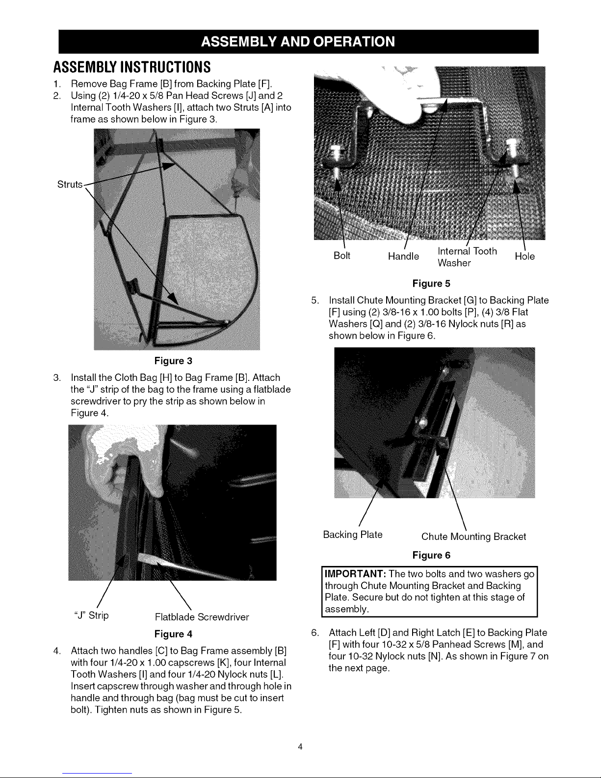
ASSEMBLYINSTRUCTIONS
1. Remove Bag Frame [B] from Backing Plate [F].
2. Using (2) 1/4-20 x 5/8 Pan Head Screws [J] and 2
Internal Tooth Washers [I], attach two Struts [A] into
frame as shown below in Figure 3.
Struts.
Figure 3
,
Install the Cloth Bag [H] to Bag Frame [B]. Attach
the "J" strip of the bag to the frame using a flatblade
screwdriver to pry the strip as shown below in
Figure 4.
Bolt Handle Internal Tooth Hole
Washer
Figure 5
,
Install Chute Mounting Bracket [G] to Backing Plate
[F] using (2) 3/8-16 x 1.00 bolts [P], (4) 3/8 Flat
Washers [Q] and (2) 3/8-16 Nylock nuts [R] as
shown below in Figure 6.
Backing Plate
Chute Mounting Bracket
"J" Strip Flatblade Screwdriver
Figure 4
,
Attach two handles [C] to Bag Frame assembly [B]
with four 1/4-20 x 1.00 capscrews [K], four Internal
Tooth Washers [I] and four 1/4-20 Nylock nuts [L].
Insert capscrew through washer and through hole in
handle and through bag (bag must be cut to insert
bolt). Tighten nuts as shown in Figure 5.
Figure 6
IMPORTANT: The two bolts and two washers go J
through Chute Mounting Bracket and Backing J
Plate. Secure but do not tighten at this stage of
assemb y.
,
Attach Left [D] and Right Latch [E] to Backing Plate
[F] with four 10-32 x 5/8 Panhead Screws [M], and
four 10-32 Nylock nuts [N]. As shown in Figure 7on
the next page.
PanHead
Screw
RightLatch
Nut
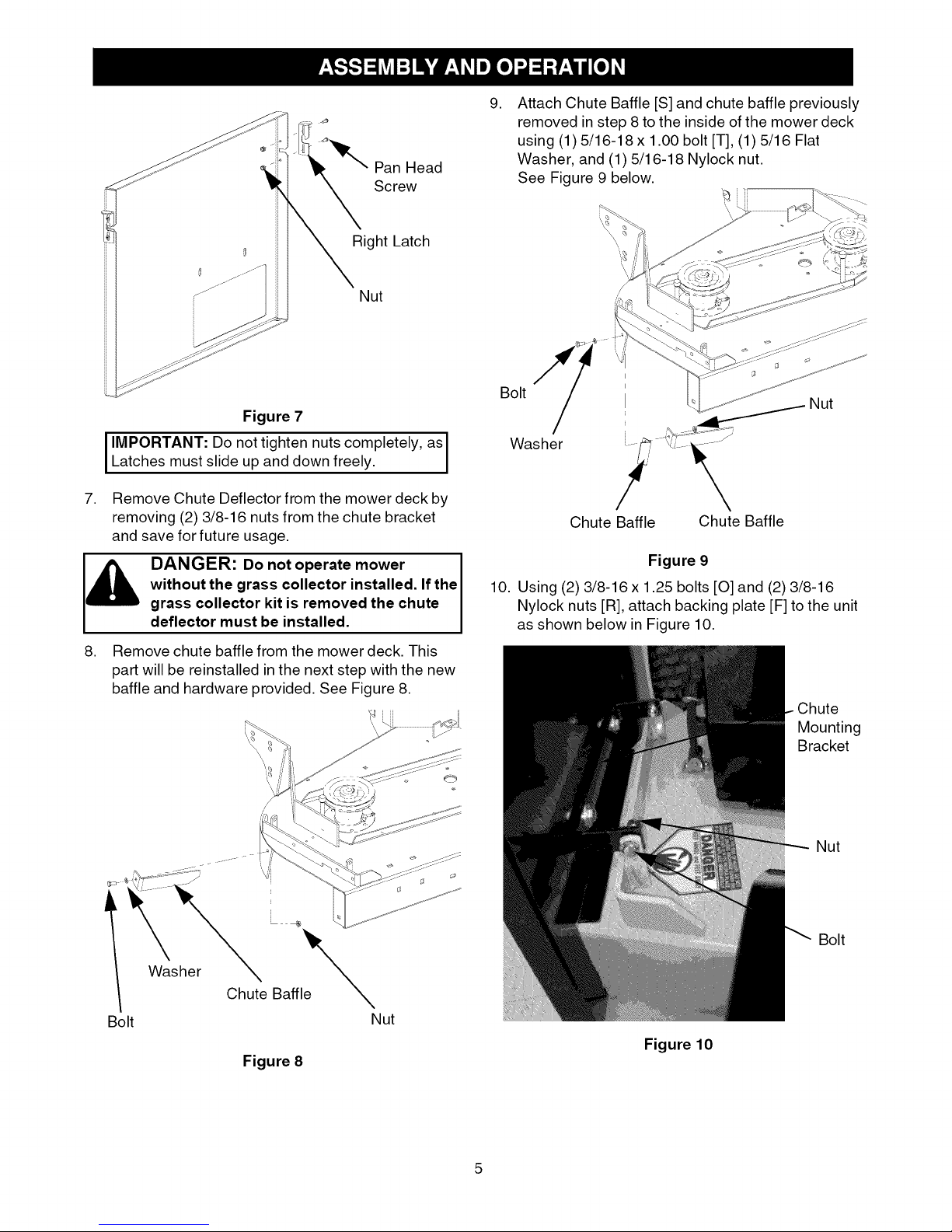
,
Attach Chute Baffle [S] and chute baffle previously
removed in step 8 to the inside of the mower deck
using (1) 5/16-18 x 1.00 bolt [T], (1) 5/16 Flat
Washer, and (1) 5/16-18 Nylock nut.
See Figure 9 below.
Figure 7
I IMPORTANT: Do not tighten nuts completely, as I
Latches must slide up and down freely.
7. Remove Chute Deflector from the mower deck by
removing (2) 3/8-16 nuts from the chute bracket
and save for future usage.
without the grass collector installed. If the
[_k, DANGER: Do not operate mower
8. Remove chute baffle from the mower deck. This
grass collector kit is removed the chute
deflector must be installed.
part will be reinstalled in the next step with the new
baffle and hardware provided. See Figure 8.
Bolt
Washer
Chute Baffle Chute Baffle
Figure 9
10. Using (2) 3/8-16 x 1.25 bolts [0] and (2) 3/8-16
Nylock nuts [R], attach backing plate [F] to the unit
as shown below in Figure 10.
Nut
Chute
Mounting
Bracket
Washer _ e_
Bolt Nut
Chute Baffl
Figure 8
Nut
Bolt
Figure 10
5
 Loading...