

Sears
OWNER'S
MANUAL
MODEL NO.
328.395900
CAUTION:
Read SAFETY
RULES and
INSTRUCTIONS
carefully
[RRFTSMRN°
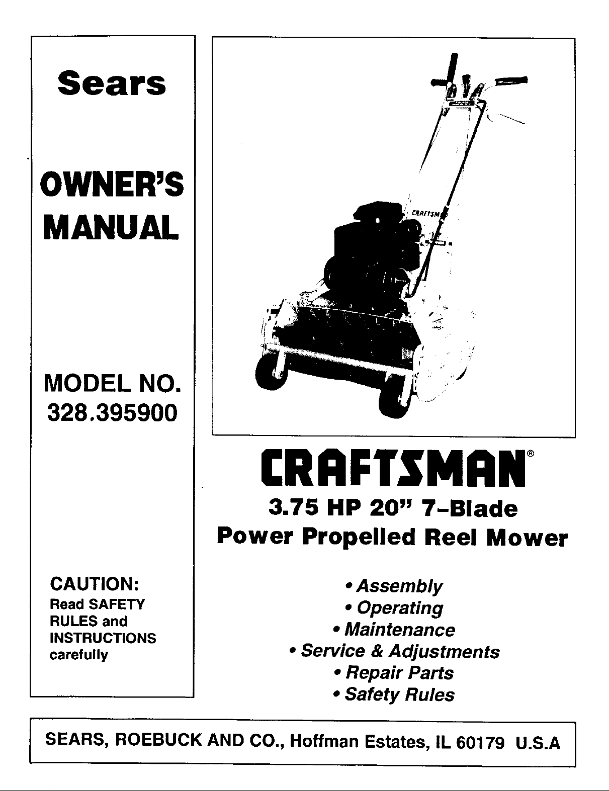
3.75 HP 20" 7-Blade
Power Propelled Reel Mower
• Assembly
• Operating
• Maintenance
• Service & Adjustments
• Repair Parts
• Safety Rules
I SEARS, ROEBUCK AND CO., Hoffman Estates, IL 60179 U.S.A I
Safety Rules
CAUTION: ALWAYS DISCONNECT SPARK PLUG WIRE AND PLACE WIRE WHERE IT
_ CANNOT CONTACT SPARK PLUG TO PREVENT ACCIDENTAL STARTING WHEN _1_
Always use care when operating the POWER REEL MOWER. Keep clear of moving parts. Do not work on POWER ]
REEL MOWER with engine running. Avoid striking or running into solid objects or debris in the area to be worked.
Read and observe the Operation Precautions. Keep the POWER REEL MOWER clean. Follow a regular]
maintenance and check schedule to provide efficient and safe operation. A well-cared-for POWER REEL MOWER
w Iast onger and operate more eff cent y, A ways be careful for yourself and for others.
Preparation
SETTING-UP,TRANSPORTING,ADJUSTINGORMAKINGREPAIRSTOYOUR
MOWER.
1. Thoroughly inspect the area where the equipment is to be used and remove all stones, sticks,
wire, bones and other foreign objects.
2. Do not operate equipment when barefoot or wearing open sandals. Always wear substantial
footwear.
3. Check fuel before starting engine. Do not fill gasoline tank indoors, when engine is running, or
while engine is still hot. Wipe off any spilled gasoline before starting engine.
4. Disengage drive clutch before starting engine.
5. Never attempt to make a wheel height adjustment while engine is running.
6. Mow only in day light or in good artificial light.
7. Never operate equipment in wet grass. Always be sure of your footing, keep a firm hold on the
handle and walk, never run.
_ti
Operation
1. Do not change engine governor settings or overspeed engine.
2. Do not puts hands or feet near or under rotating parts. Keep clear of discharge opening at all
times.
3. Stop reel blade(s) when crossing gravel drive, walks or roads.
4. After striking a foreign object, stop the engine, remove wire from spark plug, thoroughly inspect
the mower for any damage, and repair the damage before restarting and operating the mower.
5. If the equipment should start to vibrate abnormally, stop the engine and check immediately for
the cause. Vibration is generally a warning of trouble.
6. Stope engine whenever you leave the equipment, before cleaning mower housing, and when
making any repairs or inspections.
7. When cleaning, repairing or inspecting, make certain reel and all moving parts have stopped.
Disconnect spark plug wire and keep wire away from plug to prevent accidental starting.
8. Do not run engine indoors.
9. Shut engine off and wait until reel comes to a complete stop before removing grass catcher
and/or any other mower component.
10. Mow across the face of slopes, never up-and-down. Exercise extreme caution when changing
direction on slopes. Do not mow excessively steep slopes.
11. Never operate mower without proper guards, plates or other safety projective devices in place.
12. DRAIN THE GASOLINE from your mower before transporting your mower inside your car or
other vehicle.
LOOK FOR THIS SYMBOL TO POINT OUT
IMPORTANT SAFETY PRECAUTIONS. IT
MEANS - ATTENTION!H "BECOME ALERTZ!!
YOUR SAFETY IS INVOLVED.
2
CONGRATULATIONS on your purchase of a Sears Craftsman Lawn Mower. It has been
designed, engineered and manufactured to give you the best possible dependability and performance.
Should you experience any problem you cannot easily remedy, please contact your nearest Sears Service
Center/Department.
Please read and retain this manual. The instructions will enable you to assemble and maintain your mower
properly. Always observe the "SAFETY RULES".
MODELNUMBER
SERIALNUMBER
DATEOF PURCHASE
THE MODELAND SERIALNUMBERSWILLBEFOUNDON ADECALATTACHEDTO THE REAROF THE MOWERHOUSING,
YOU SHOULDRECORDBOTHSERIALNUMBERAND DATEOF PURCHASEANDKEEPINASAFE PLACEFOR FUTURE REFERENCE.
MAINTENANCE AGREEMENT
A Sears Maintenance Agreement is available on thisproduct.Contact your nearest Sears store for details.
CUSTOMER RESPONSIBILITIES
• Read and observe the safety rules.
• Followa regularschedule in maintaining,caringfor and usingyour mower.
• Followthe instructionsunder "Maintenance" and "Storage" sectionso this Owner's Manual.
PRODUCT SPECIFICATIONS
HORSE POWER: 3.75
DISPLACEMENT: 9.02
GASOLINE CAPACITY: 2 quart (Unleaded)
Oil (1-1/4 Pt. Capacity): SAE 30W SAE lOW30
SPARK PLUG (Gap .030 in.): Champion ShortCJ-8 Long J-gC
VALVE CLEARANCE: Intake: .005"- .OOT' Exhaust: .007"-.009"
Craftsman Warranty
Two year limited warranty on Craftsman lawn mowers:
For two years from the date of purchase, when this Craftsman lawn mower is
maintained, lubricated and tuned-up according to the instructions in the owner's
manual, Sears will repair, free of charge any defect in material and workmanship.
If this Craftsman lawn mower is used for commercial or rental purposes, this
warranty applies for only 90 days from the date of purchase.
This warranty does not cover:
• Expendable items which become worn during normal use, such as rotary mower and/or edger blades,
belts, blade guard, blade adapters, air cleaners, spark plugs, tire chains and shear pins.
• Repairs necessary because of operator abuse or negligence, including bent crankshafts and the failure
to maintain the equipment according to the instructions contained in the owner's manual.
WARRANTY SERVICE IS AVAILABLE BY RETURNING THE CRAFTSMAN LAWN MOWER TO THE
NEAREST SERVICE CENTER/DEPARTMENT IN THE UNITED STATES.
This warrantygives you specific legal rights,andyoumayalsohaveotherrightswhichvaryfromstatetostate.
SEARS, ROEBUCK AND CO., Hoffman Estates, IL 60179
3
TABLE OF CONTENTS
SAFETY RULE ......................... 2
PRODUCT SPECIFICATIONS .............. 3
CUSTOMER RESPONSIBILITIES ........... 3
WARRANTY ........................... 3
TABLE OF CONTENTS ................... 4
INDEX ................................ 4
MOWER ACCESSORIES .................. 4
ASSEMBLY ........................ 5, 6, 7
INDEX
A
Adjustments:
Carburetor ................... 11
Engine Speed ................ 10
Heightof Cut .................. 9
Air Filter:
Cleaning .................... 10
PaperCartridge ............... t0
Replacement................. 10
Assembly:
Handle ...................... 5
Accessories..................... 4
C
Controls:
EngineControl ............. 9, 10
Speed Selector ................ 9
Customer Responsibilities .......... 3
Cutting Levels ................... g
E
Engine:
Control .................... 9 10
Oil Cap ...................... 7
Oil Change .................. 10
Oil Level ..................... 7
OilType ...................... 7
Starting ...................... 9
Storage ..................... 12
F
Filter,Air ...................... 10
Fuel:
Type ........................ 7
Storage ....................... 12
Gasoline ....................... 7
Handle:
AssemtYy ................ 5, 6, 7
Height, Cutting ................ 9
Index .......................... 4
Lubrication:
Chain ...................... 10
Engine ................... 7, 10
Maintenance:
Agreement ................... 3
AirFilter .................... 10
Air Filter
PaperCartridge ............... 10
Engine ..................... 10
GrassCatcher ................. 7
Lubrication .................. 10
SparkPlugs ................. 10
MowingTips ................... 2, 9
Oil:
Engine ...................... 7
Storage ..................... 12
Operation:
Operating Mower............. 8, 9
Speed:
Starting the Engine ............. 9
Stopping Your Lawn Mower ....... 9
OPERATION ........................ 7, 8; 9
MAINTENANCE ........................ 10
SERVICE & ADJUSTMENT ............... 11
STORAGE ............................ 12
TROUBLE SHOOTING ................... 13
REPAIR PARTS--MOWER ............. 14, 15
REPAIR PARTS--ENGINE ............. 16, 17
PARTS ORDERING/SERVICE ............. 20
G
Repair/Replacement:
H
I
L
M
O
Parts .................... 14, 15
Customer
Responsibilities .................. 3
Safety Rules .................... 2
Service and Adjustments:
Carburetor ................... 11
Cutting Level .................. 9
Engine .................. 10, 11
Service
Recommendation ................ 10
Spark Plugs .................... 10
Specifications .................... 3
Speed Control:
Engine ...................... 9
Starting the Engine:
Starter Rope .................. 9
Steppingthe Mower ............ 9
Storage ....................... 12
Table of Contents ................. 4
Trouble Shooting
Chart ......................... 13
Warranty ....................... 3
R
S
T
w
MOWER ACCESSORIES
These accessories were available when the mower was purchased.
They are also available at almost Sears retail outlets, catalog and
service centers, most sears stores can order repair parts for you,
when you provide the model number your mower.
ENGINE
SPARKPLUG MUFFLER AIR FILTER GAS CAN ENGINE OtL STABILIZER
4
Assembly
TOOLS REQUIRED: 7/16" Wrench, Pliers, Screwdriver (11/16" Wrench needed to adjust Clutch Tension)
NOTE: Reference to left or right side
of the mower is from operator's
position at the handle, facing forward.
The lawn mower is fully assembled
except for the handle throttle control,
drive control rod and clutch control
rod. Everything is packed and shipped
in one container.
ASSEMBLY:
1. CARTON REMOVAL
Cut the back panel, lay down pull
mower backwards.
2. PARTS ID
3. TOOLS REQUIRED
7/16" Wrench, Pliers, Screwdriver
(11/16" Wrench needed to adjust
Clutch Tension)
STEP 1: Remove the grass catcher,
handle assembly, and rods from the box
(see Fig. 1, grass catcher not shown).
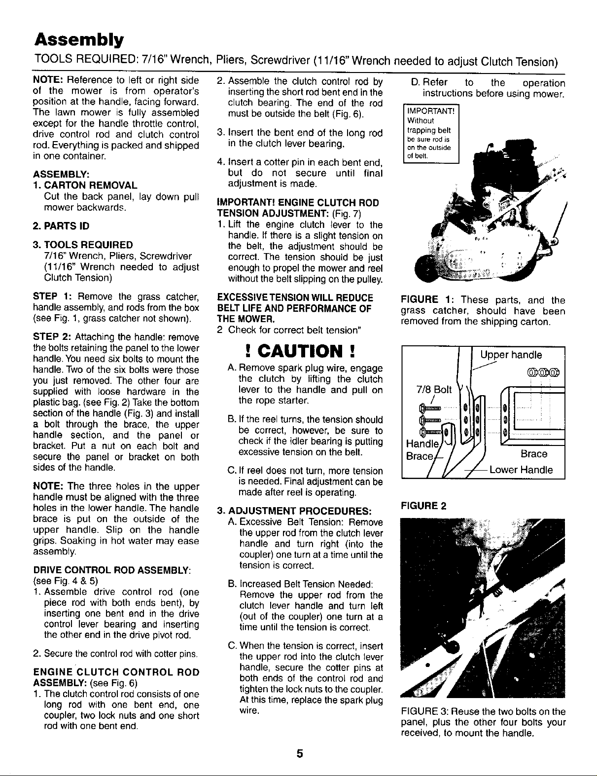
STEP 2: Attaching the handle: remove
the bolts retainingthe panel to the lower
handle.You need six boltsto mount the
handle.Two of the six bolts were those
you just removed. The other four are
supplied with loose hardware in the
plasticbag. (see Fig, 2) Takethe bottom
sectionof the handle (Fig. 3) and install
a bolt through the brace, the upper
handle section, and the panel or
bracket. Put a nut on each bolt and
secure the panel or bracket on both
sides of the handle.
NOTE: The three holes in the upper
handle must be aligned with the three
holes in the lower handle. The handle
brace is put on the outside of the
upper handle. Slip on the handle
grips. Soaking in hot water may ease
assembly.
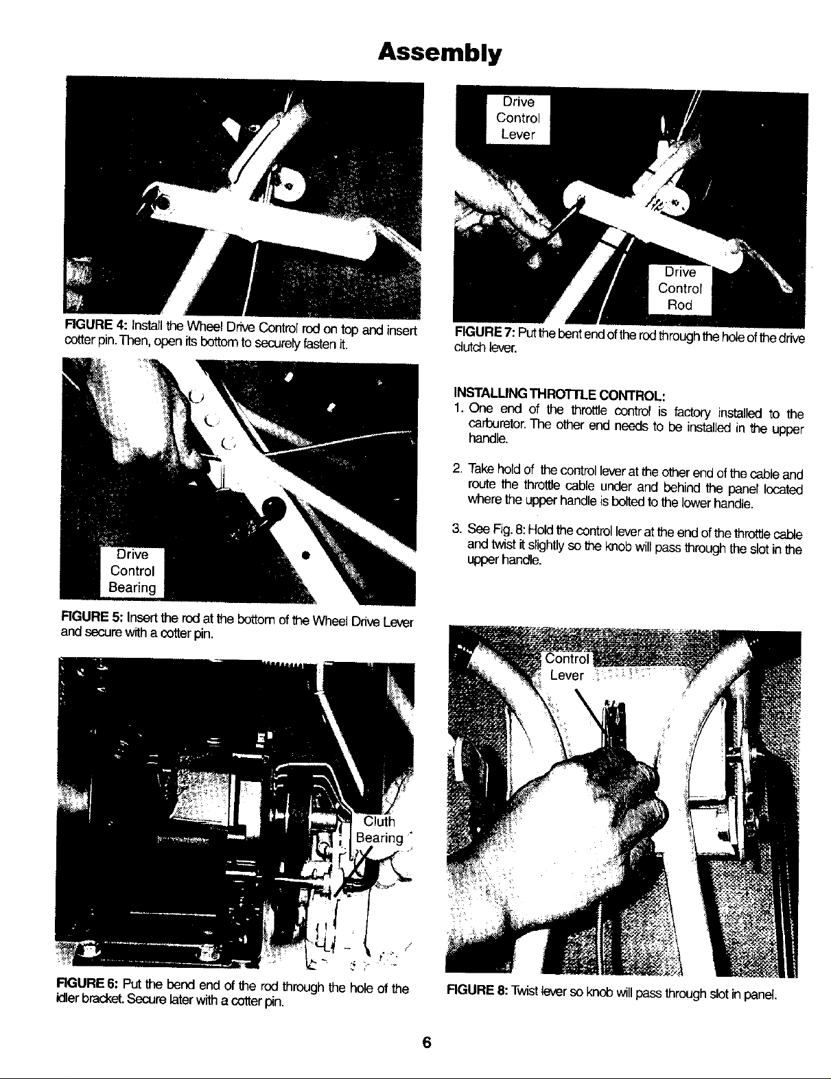
DRIVE CONTROL ROD ASSEMBLY:
(see Fig. 4 & 5)
1. Assemble drive control rod (one
piece rod with both ends bent), by
inserting one bent end in the drive
control lever bearing and inserting
the other end inthe drive pivot rod.
2. Secure the control rodwith cotter pins.
ENGINE CLUTCH CONTROL ROD
ASSEMBLY: (see Fig. 6)
1. The clutch controlrodconsistsof one
long rod with one bent end, one
coupler, two lock nuts and one short
rodwith one bent end.
2.
Assemble the clutch control rod by
inserting the short rod bent end in the
clutch bearing. The end of the rod
must be outside the belt (Fig. 6).
3. Insert the bent end of the long rod
in the clutch lever bearing.
4. Insert a cotter pin in each bent end,
but do not secure until final
adjustment is made.
IMPORTANT! ENGINE CLUTCH ROD
TENSION ADJUSTMENT: (Fig. 7)
1. Lift the engine clutch lever to the
handle. Ifthere is a slighttensionon
the belt, the adjustment should be
correct. The tension should be just
enough to propelthe mower and reel
withoutthe belt slipping onthe pulley.
EXCESSIVE TENSION WILL REDUCE
BELT LIFE AND PERFORMANCE OF
THE MOWER,
2 Check for correct belt tension"
! CAUTION !
A. Remove spark plug wire, engage
the clutch by lifting the clutch
lever to the handle and pull on
the rope starter.
B. If the reel turns, the tension should
be correct, however, be sure to
check if the idler bearing is putting
excessive tension on the belt.
C. If reel does not turn, more tension
is needed. Final adjustment can be
made after reel is operating.
3. ADJUSTMENT PROCEDURES:
A. Excessive Belt Tension: Remove
the upper rodfrom the clutchlever
handle and turn right (into the
coupler)one turnat a time until the
tensionis correct.
B. Increased Belt Tension Needed:
Remove the upper rod from the
clutch lever handle and turn left
(out of the coupler) one turn at a
time until the tension is correct.
C. When the tension is correct, insert
the upper rod into the clutch lever
handle, secure the cotter pins at
both ends of the control rod and
tighten the lock nuts to the coupler.
At this time, replace the spark plug
wire.
D. Refer to the operation
instructions before using mower.
be sure rod is
on the outside
FIGURE 1: These parts, and the
grass catcher, should have been
removed from the shipping carton.
Upper handle
7/8 Bolt
Brace
-Lower Handle
FIGURE 2
FIGURE 3: Reuse the two bolts on the
panel, plus the other four bolts your
received, to mount the handle.
5
Assembly
FIGURE 4: Installthe Wheel DriveControl rodon top and insert
cotter pin.Then, open itsbottom to securely fastenit.
RGURE 5: Insert the rod atthe bottom ofthe Wheel DriveLever
and secure with a cotter pin.
FIGURE7: Putthe Pentendofthe rodthroughtheholeof thedrive
dutch lever.
INSTALLING THRO'I-rLE CONTROL.
1. One end of the throttle control is factory installed to the
carburetor.The other end needs to be installed in the upper
handle,
2. Take hold of the controlleveratthe other end ofthe cableand
route the throttle cable under and behind the panel located
where the upper handle is peltedto the lower handle.
3. See Fig. 8: Holdthe control leverat the end ofthe throttle cable
andtwist it slightlyso _e knob willpass through the slot inthe
upper handle.
Cluth
t'i ¸_.
RGURE 6: PUtthe bend end of the rod through the hole ofthe
idler bracket.Securelaterwitha cotter p_n.
J
RGURE 8: Twistleverso knob willpass through slot in panel.
6
 Loading...