

Craftsman 320.48251 Owner's Manual
Owner's Manua
Model No.
320.48251
/k
Z___.wCAUTION: Read, understand and
follow all Safety Rules and Operating
Instructions in this manual before using
this product.
, SAFETY
• OPERATION
° MAINTENANCE
"ESPAI_IOL, PAGINA 17
Sears, Roebuck and Co., Hoffman Estates, IL 60179 U.S.A.
Warranty. ............................................................ Page 2
Safety Instructions ........................................... Page 3
Description ......................................................... Page 4
Operation ....................................................... Pages 5 -12
Maintenance ...................................................... Page 13
TroubleShooting ................................................ Page 14
Service Numbers ............................................... Back Cover
FULL ONE YEAR WARRANTY ON CRAFTSMAN
LASER LEVEL
If this CRAFTSMAN Laser Level fails to give complete satisfaction
within one year from the date of purchase, RETURN IT TO THE
NEAREST SEARS STORE IN THE UNITED STATES, and Sears
will replace it, free of charge.
If this CRAFTSMAN Laser Level is used for commercial or rental
purposes, this warranty applies for only 90 days from the date
of purchase.
This warranty gives you specific legal rights, and you may also
have other rights which vary from state to state.
Sears, Roebuck and Co., Depto 817WA, Hoffman Estates, IL 60179
SAVETHESE INSTRUCTIONS!
READ ALL INSTRUCTIONSt
2
j WARNING: BE SURE to read and understand all instructions in this
manual before using this level. Failure to follow all instructions may result in
hazardous radiation exposure, electric shook, fire, and/or bodily injury.
IIIII I: ............
CAUTION: Use of controls or adjustments or performance of
procedures other than those specified herein, may result in hazardous radiation
exposure°
CAUTION; The use of optical instruments with this product will increase
eye hazard.
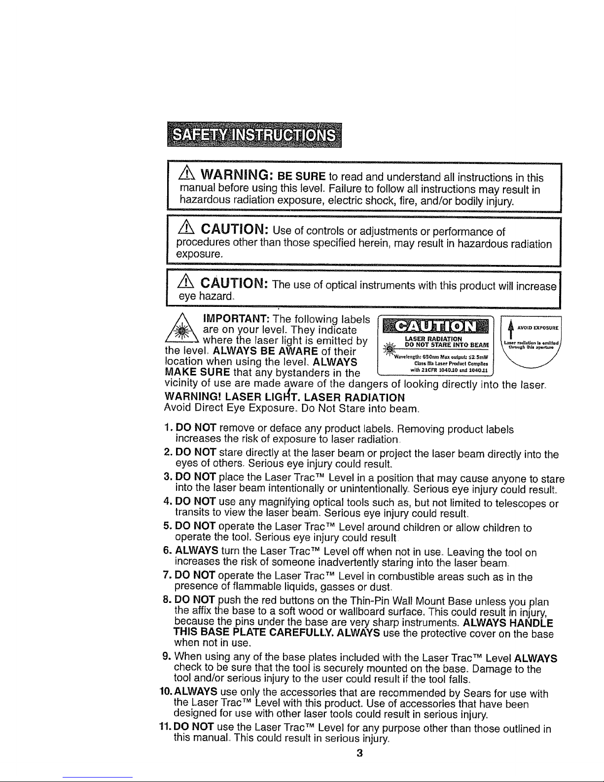
z_ IMPORTANT: The following labels
are on your level. They indicate
where the laser light is emitted by
the level.. ALWAYS BE AWARE of their
location when using the level ALWAYS
LASER RADIATION {
DO NOT STARE INTO REAM _La_er radJat_(_n_IsCmll|_d
C_s DL_ ,t._:ser Produ¢! CQmpne_
MAKE SURE that any bystanders in the .i,,2=c_=o4o._o,._1o,o_
vicinity of use are made aware of the dangers of looking directly into the laser.
WARNING! LASER LIGI-{T. LASER RADIATION
Avoid Direct Eye Exposure° Do Not Stare into beam_
1. DO NOT remove or deface any product labels. Removing product labels
increases the risk of exposure to laser radiation
2. DO NOT stare directly at the laser beam or project the laser beam directly into the
eyes of others. Serious eye injury could result.
3. DO NOT place the Laser Trac TM Level in a position that may cause anyone to stare
into the laser beam intentionally or unintentionally. Serious eye injury could result,,
4. DO NOT use any magnifying optical tools such as, but not limited to telescopes or
transits to view the laser beam. Serious eye injury could result.
5. DO NOT operate the Laser Trac TM Level around children or allow children to
operate the toolo Serious eye injury could result
6. ALWAYS turn the Laser Trac TM Level off when not in use, Leaving the tool on
increases the risk of someone inadvertently staring into the laser beam
7. DO NOT operate the Laser Trac TM Level in combustible areas such as in the
presence of flammable liquids, gasses or dust.
8. DO NOT push the red buttons on the Thin-Pin Wall Mount Base unless you plan
the affix the base to a soft wood or wallboard surface° This could result in injury,
because the pins under the base are very sharp instruments. ALWAYS HANDLE
THIS BASE PLATE CAREFULLY. ALWAYS use the protective cover on the base
when not in use.
9. When using any of the base plates included with the Laser Trac TM Level ALWAYS
check to be sure that the tool is securely mounted on the base. Damage to the
tool and/or serious injury to the user could result if the tool fall&
10. ALWAYS use only the accessories that are recommended by Sears for use with
the Laser Trac TM Level with this product. Use of accessories that have been
designed for use with other laser tools could result in serious injury°
11. DO NOT use the Laser Trac TM Level for any purpose other than those outlined in
this manual This could result in serious injury,.
3
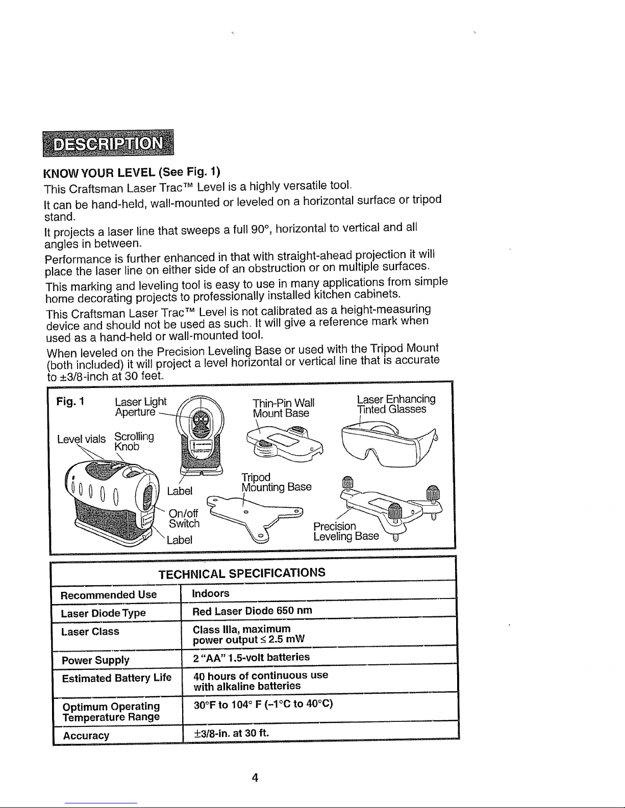
KNOWYOUR LEVEL (See Fig. 1)
This Craftsman Laser Trac TM Level is a highly versatile tool.
tt can be hand-held, wall-mounted or leveled on a horizontal surface or tripod
stand_
it projects a laser line that sweeps a full 90°, horizontal to vertical and all
angles in between.
Performance is further.enhanced in that with straight-ahead projection it wilt
place the laser line on either side of an obstruction or on multiple surfaces,
This marking and leveling tool is easy to use in many applications from simple
home decorating projects to professionally installed kitchen cabinets.
This Craftsman Laser Trac TM Level is not calibrated as a height-measuring
device and should not be used as such. It wil! give a reference mark when
used as a hand-held or wall-mounted tool.
When leveled on the Precision Leveling Base or used with the Tripod Mount
(both included) it will project a level horizontal or vertical line that is accurate
to ±3/8-inch at 30 feet.
Fig, 1 Laser Light •_ Thin-Pin Walt Laser Enhancing
Aperture -___ _ Mount Base Tinted Glasses
Level vials Scrolling '
Knob
Tripod
-_ Label Mounting Base
On/off
Switch Preci
Label Leveling Base "_
i ................... i, -
TECHNICAL SPECIFICATIONS
, ,,,,,,,..... i , .....
Recommended Use Indoors
Laser Diode Type Red Laser Diode 650 nm
Laser Class Class Ilia, maximum
power output _<23 mW
,,,,,,, L..... ,,.....
Power Supply 2 "AA" 1.5-volt batteries
Estimated Battery Life 40 hours of continuous use
with alkaline batteries
Optimum Operating 30°F to 104° F (-1°C to 40°C)
Temperature Range
, ,,,,,, .......
Accuracy _+3t8-in.at 30 ft.
4
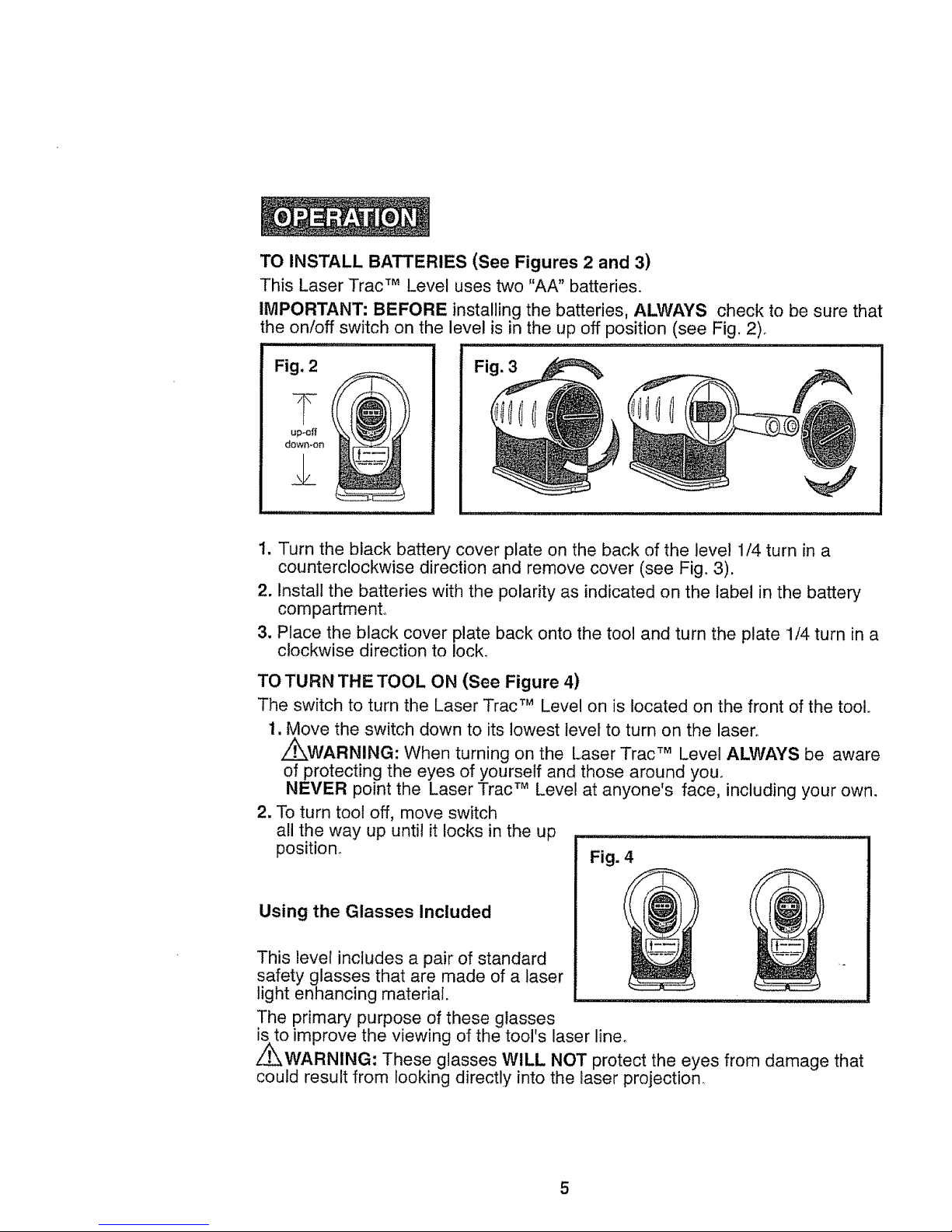
TO INSTALL BATTERIES (See Figures 2 and 3)
This Laser Trac TM Level uses two "AA" batteries,
IMPORTANT: BEFORE installing the batteries, ALWAYS
the on/off switch on the level is in the up off position (see Fig. 2)°
Fig. 2
up-elf
down-on
,2
Fig. 3
check to be sure that
1. Turn the black battery cover plate on the back of the level 1/4 turn in a
counterclockwise direction and remove cover (see Fig. 3).
2, Install the batteries with the polarity as indicated on the label in the battery
compartment,,
3. Place the black cover plate back onto the tool and turn the plate 1/4 turn in a
clockwise direction to lock,
TO TURN THE TOOL ON (See Figure 4)
The switch to turn the Laser Trac TM Level on is located on the front of the toolo
1, Move the switch down to its lowest level to turn on the laser°
z_WARNING: When turning on the Laser Trac TM Level ALWAYS be aware
of protecting the eyes of yourself and those around you°
NEVER point the Laser Trac TM Level at anyone's face, including your own.
2, To turn tool off, move switch
all the way up until it locks in the up
position,
Using the Glasses Included
Fig. 4
This level includes a pair of standard ._
safety glasses that are made of a laser
light enhancing material.
The primary purpose of these glasses
is to improve the viewing of the tool's laser lineo
Z_WARNING: These glasses WILL NOT protect the eyes from damage that
could result from looking directly into the laser projection,
5
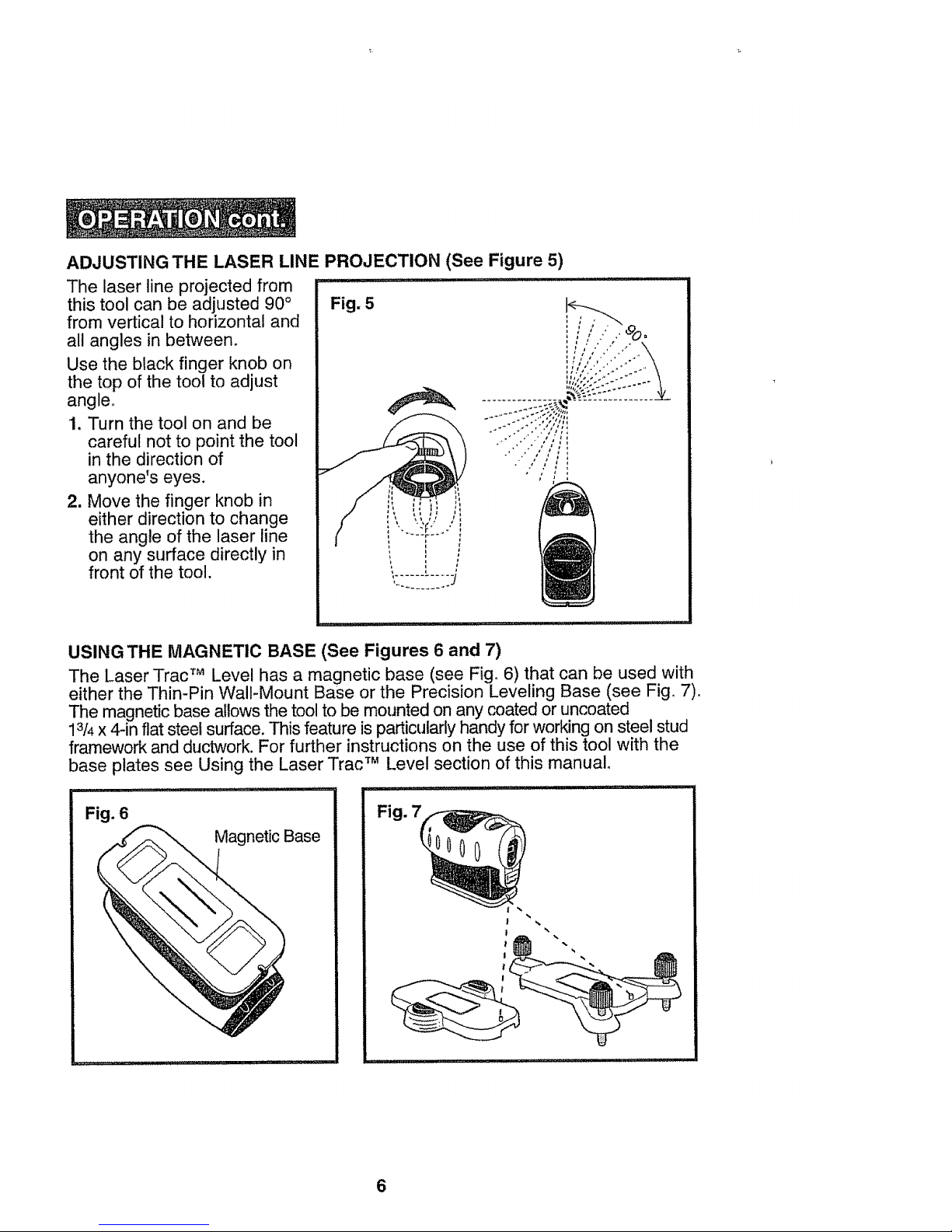
ADJUSTING THE LASER LINE PROJECTION (See Figure 5)
The laser line projected from
this tool can be adjusted 90 °
from vertical to horizontal and
all angles in between,
Use the black finger knob on
the top of the tool to adjust
angle,
1. Turn the tool on and be
careful not to point the tool
in the direction of
anyone's eyes.
2. Move the finger knob in
either direction to change
the angle of the laser line
on any surface directly in
front of the tool.
Fig. 5
USING THE MAGNETIC BASE (See Figures 6 and 7)
The Laser Trac TM Level has a magnetic base (see Fig. 6) that can be used with
either the Thin-Pin Wall-Mount Base or the Precision Leveling Base (see Fig. 7).
The magnetic base allows the tool to be mounted on any coated or uncoated
13/4x 4-in flat steel surface. This feature is particularly handy for working on steel stud
framework and duct_,_lork.For further instructions on the use of this tool with the
base plates see Using the Laser Trac TM Level section of this manual,
un,, i,lll,ll,,,,H,_, ............ i i,lll,ll i,llL,,,uH,,,,lln,,lll ,i,tl
Magnetic Base
Fig.
Fig. 6
6
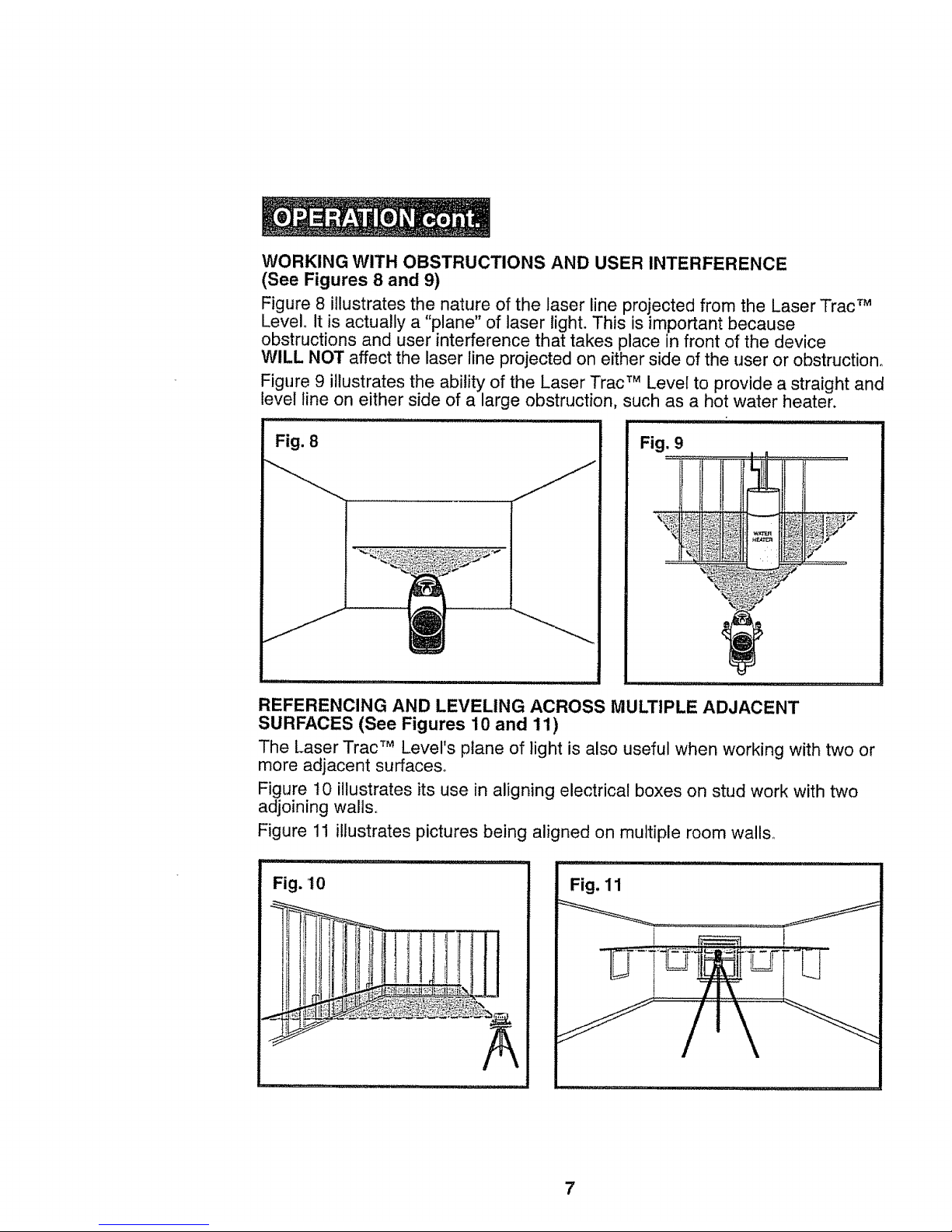
WORKINGWITH OBSTRUCTIONS AND USER INTERFERENCE
(See Figures 8 and 9)
Figure 8 illustrates the nature of the laser line projected from the Laser Trac TM
Level° It is actually a "plane" of laser light. This is important because
obstructions and user interference that takes place in front of the device
WILL NOT affect the laser line projected on either side of the user or obstruction.
Figure 9 illustrates the ability of the Laser Trac TM Level to provide a straight and
level line on either side of a large obstruction, such as a hot water heater.
Fig. 8
Fig. 9
REFERENCING AND LEVELING ACROSS MULTIPLE ADJACENT
SURFACES (See Figures 10 and 11)
The Laser Trac TM Level's plane of light is also useful when working with two or
more adjacent surfaces_
Figure t0 illustrates its use in aligning electrical boxes on stud work with two
adjoining walls,,
Figure 11 illustrates pictures being aligned on multiple room walls.
Fig. 10
Fig. 11
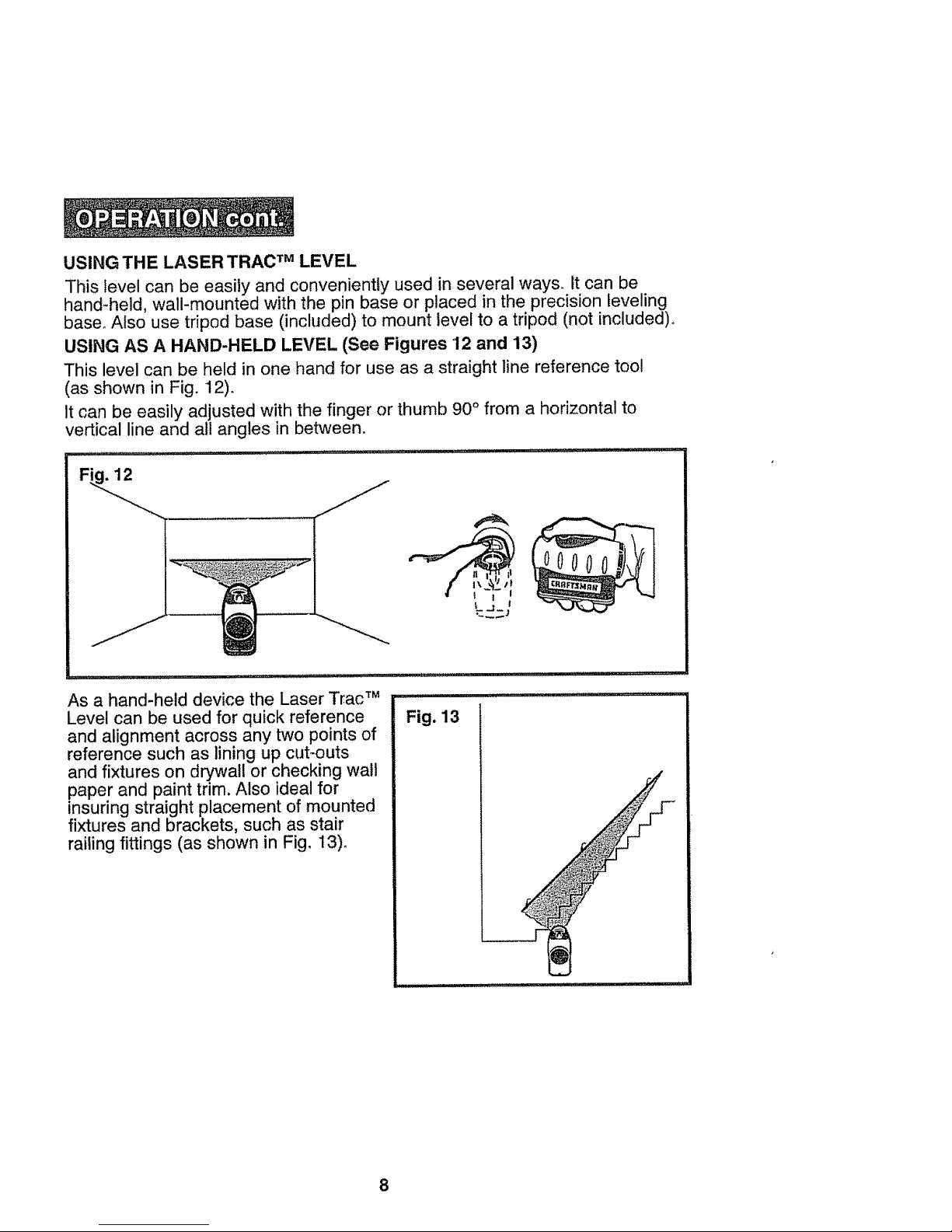
USING THE LASER TRAC TM LEVEL
This level can be easily and conveniently used in several ways, it can be
hand-held, wall-mounted with the pin base or placed in the precision leveling
base_ Also use tripod base (included) to mount level to a tripod (not included)_
USING AS A HAND-HELD LEVEL (See Figures 12 and 13)
This level can be held in one hand for use as a straight line reference tool
(as shown in Fig. 12).
It can be easily adjusted with the finger or thumb 90 ° from a horizontal to
vertical line and all angles in between.
As a hand-held device the Laser Trac TM
Level can be used for quick reference
and alignment across any two points of
reference such as lining up cut-outs
and fixtures on drywall or checking wall
paper and paint trim. Also ideal for
insuring straight placement of mounted
fixtures and brackets, such as stair
railing fittings (as shown in Fig. 13).
Fig. 13
8
USING THE LASER TRAC TM LEVEL (cont.)
USING AS A WALL-MOUNTED LEVEL (See Figures 14 to 17)
This level can also be wall-mounted using the special base included.
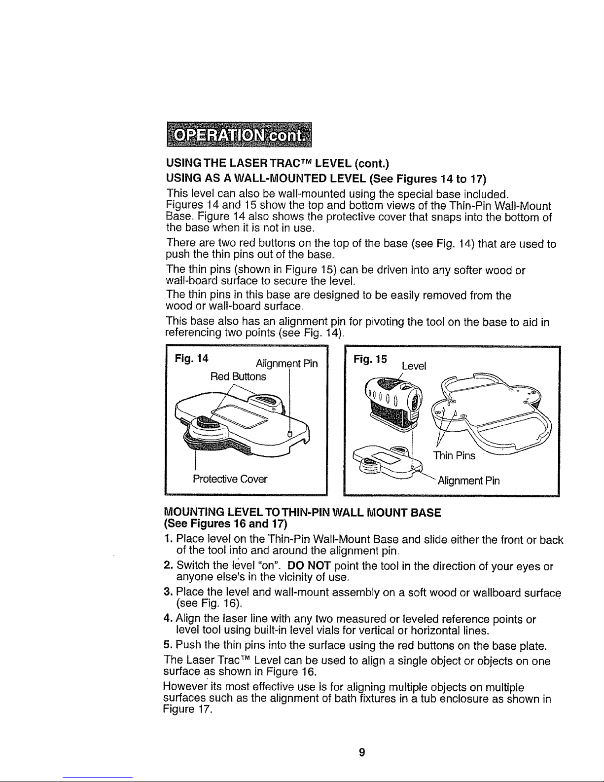
Figures 14 and 15 show the top and bottom views of the Thin-Pin Wall-Mount
Base° Figure 14 also shows the protective cover that snaps into the bottom of
the base when it is not in use.
There are two red buttons on the top of the base (see Fig° 14) that are used to
push the thin pins out of the base.
The thin pins (shown in Figure 15) can be driven into any softer wood or
wal!-board surface to secure the level,,
The thin pins in this base are designed to be easily removed from the
wood or wall-board surface.
This base also has an alignment pin for pivoting the tool on the base to aid in
referencing two points (see Fig. 14),_
Fig. 14
Alignment Pin
Red Buttons
Protective Cover
Fig. 15
Level
Thin Pins
Alignment Pin
MOUNTING LEVEL TO THIN-PIN WALL MOUNT BASE
(See Figures 16 and 17)
1. Place level on the Thin-Pin Wall-Mount Base and slide either the front or back
of the tool into and around the alignment pin°
2. Switch the level "on'L DO NOT point the tool in the direction of your eyes or
anyone else's in the vicinity of use.
3. Place the level and wall-mount assembly on a soft wood or wallboard surface
(see Fig. 16).
4. Align the laser line with any two measured or leveled reference points or
level tool using built-in level vials for vertical or horizontal lines.
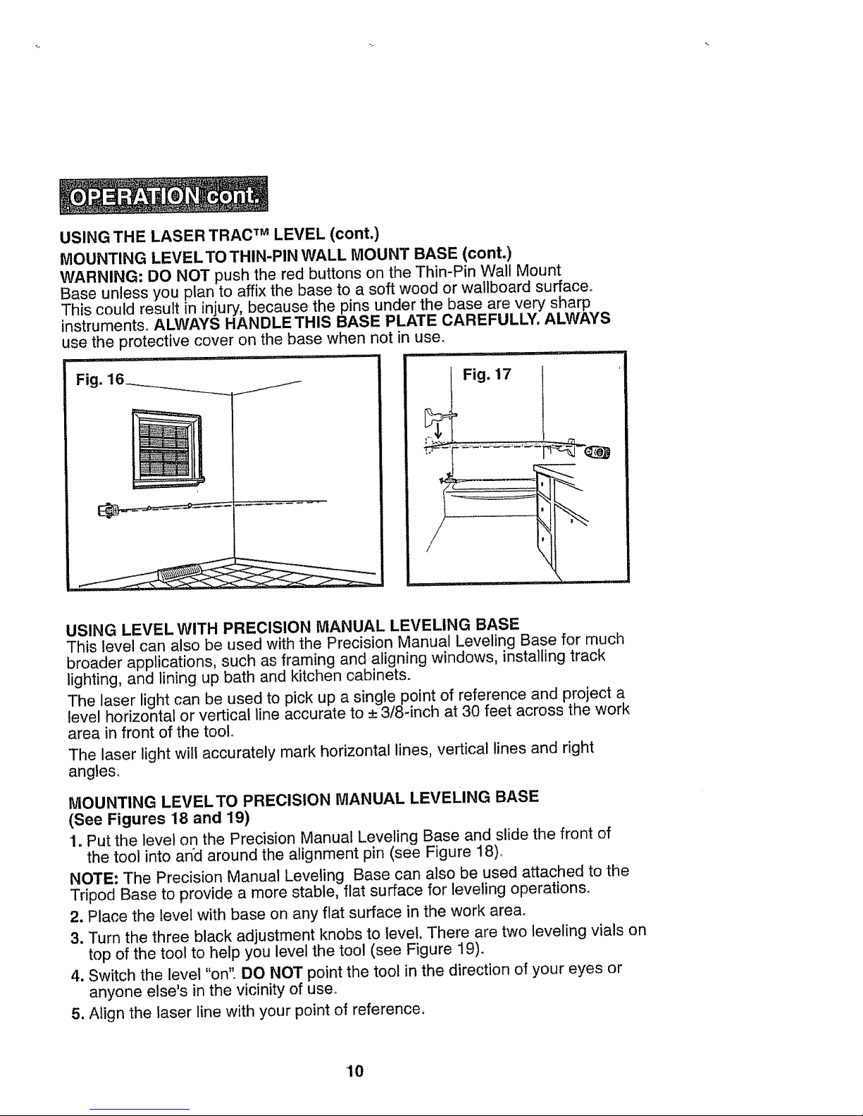
5. Push the thin pins into the surface using the red buttons on the base plate.
The Laser Trac TM Level can be used to align a single object or objects on one
surface as shown in Figure 16.
However its most effective use is for aligning multiple objects on multiple
surfaces such as the alignment of bath fixtures in a tub enclosure as shown in
Figure !7.
9
USINGTHE LASERTRACTM LEVEL (cont.)
MOUNTING LEVEL TO THIN-PIN WALL MOUNT BASE (cont.)
WARNING: DO NOT push the red buttons on the Thin-Pin Wall Mount
Base unless you plan to affix the base to a soft wood or wallboard surface.
This could result in injury, because the pins under the base are very sharp
instruments, ALWAYS HANDLE THIS BASE PLATE CAREFULLY. ALWAYS
use the protective cover on the base when not in use°
Fig. '16__._.__i_I_
Fig. 17
USING LEVEL WITH PRECISION MANUAL LEVELING BASE
This level can also be used with the Precision Manual Leveling Base for much
broader applications, such as framing and aligning windows, installing track
lighting, and lining up bath and kitchen cabinets.
The laser light can be used to pick up a single point of reference and project a
level horizontal or vertical line accurate to _+.3/8-inch at 30 feet across the work
area in front of the toolo
The laser light will accurately mark horizontal lines, vertical lines and right
angies_
MOUNTING LEVEL TO PRECISION MANUAL LEVELING BASE
(See Figures 18 and 19)
1. Put the level on the Precision Manual Leveling Base and slide the front of
the tool into and around the alignment pin (see Figure 18)o
NOTE: The Precision Manual Leveling Base can also be used attached to the
Tripod Base to provide a more stable, flat surface for leveling operations_
2. Place the level with base on any flat surface in the work area.
3. Turn the three black adjustment knobs to level. There are two leveling vials on
top of the tool to help you level the tool (see Figure 19).
4. Switch the level "on". DO NOT point the tool in the direction of your eyes or
anyone else's in the vicinity of use,
5. Align the laser line with your point of reference.
10
 Loading...