

Craftsman 320.46123 Operator's Manual

Operator’s Manual
12 Amp 7 1/4 in. CIRCULAR SAW
Model No. 320.46123
Sears Brands Management Corporation, Hoffman Estates,
IL 60179 U.S.A.
www.craftsman.com
• WARRANTY
• SAFETY
• DESCRIPTION
• ASSEMBLY
• OPERATION
• MAINTENANCE
• ESPAÑOL
ѥWARNING: To reduce the risk of injury,
the user must read and understand the
Operator’s Manual before using this product.
amperes
hertz
watts
kilowatts
hours
minutes
seconds
no-load speed
Revolutions or reciprocations per minute
Direct current
Alternating current
Class II tool
IP symbol
Read The Operator’s Manual
UL
h
s

2
TABLE OF CONTENTS
Warranty Page 2
Safety Symbols Pages 4-5
Safety Instructions Pages 6-10
Description Pages 11-12
Assembly Pages 13-14
Operation Pages 15-24
Maintenance Page 25
Troubleshooting Page 26
Parts List Page 27
CRAFTSMAN LIMITED WARRANTY
FOR ONE YEAR from the date of sale, this product is warranted against any
defects in material or workmanship.
WITH PROOF OF SALE, a defective product will be replaced free of charge.
For warranty coverage details to obtain free replacement, visit the web
page: www.craftsman.com/warranty
This warranty does not cover the blade or blade wrench, which are
expendable parts that can wear out from normal use within the
warranty period.
This ONE YEAR warranty is void if this product is ever used while providing
commercial services or if rented to another person. For 90 DAY commercial
and rental use terms, see the Craftsman warranty web page.
This warranty gives you specic legal rights, and you may also have other
rights which vary from state to state.
Sears Brands Management Corporation, Hoffman Estates, IL 60179.
SAVE THESE INSTRUCTIONS!
READ ALL INSTRUCTIONS!
© Sears Brands, LLC

3
This circular saw has many features for making its use more pleasant and
enjoyable. Safety, performance, and dependability have been given top priority
in the design of this product, making it easy to maintain and operate.
ѥDANGER: People with electronic devices, such as pacemakers, should
consult their physician(s) before using this product. Operation of electrical
equipment in close proximity to a heart pacemaker could cause interference or
failure of the pacemaker.
ѥWARNING: Some dust created by power sanding, sawing, grinding, drilling
and other construction activities contains chemicals known to the state of
California to cause cancer, birth defects or other reproductive harm. Some
examples of these chemicals are:
• Lead from lead-based paints
• Crystalline silica from bricks and cement and other masonry products, and
• Arsenic and chromium from chemically-treated lumber.
Your risk from these exposures varies, depending on how often you do this type
of work. To reduce your exposure to these chemical: work in a well-ventilated
area, and work with approved safety equipment, such as those dust masks that
are specially designed to lter out microscopic particles.

4
SAFETY SYMBOLS
The purpose of safety symbols is to attract your attention to possible dangers.
The safety symbols and the explanations with them deserve your careful
attention and understanding. The symbol warnings do not, by themselves,
eliminate any danger. The instructions and warnings they give are no substitutes
for proper accident prevention measures.
ѥWARNING: Be sure to read and understand all safety instructions in this
manual, including all safety alert symbols such as “DANGER,” ”WARNING,”
and “CAUTION” before using this tool. Failure to follow all instructions listed in
this manual may result in electric shock, fire and/or serious personal injury.
SYMBOL SIGNAL MEANING
SAFETY ALERT SYMBOL: Indicates DANGER, WARNING, or CAUTION; may
be used in conjunction with other symbols or pictographs.
ѥDANGER: Indicates a hazardous situation which, if not avoided, will result in
death or serious injury.
ѥWARNING: Indicates a hazardous situation which, if not avoided, could
result in death or serious injury.
ѥCAUTION: Indicates a hazardous situation which, if not avoided, could
result in minor or moderate injury.
Damage prevention and information messages
These inform the user of important information and/or instructions that could
lead to equipment or other property damage if they are not followed. Each
message is preceded by the word “NOTICE”, as in the example below:
NOTICE: Equipment and/or property damage may result if these instructions are
not followed.
ѥWARNING: To ensure safety and reliability, all repairs should be performed
by a qualified service technician.
A Amperes Current
Hz Hertz Frequency (cycles per second)
W Watt Power
min Minutes Time
Alternating Current Type of current
Direct Current Type or a characteristic of current
Rotational speed, at no load
Class II Construction Double-insulated construction
.../min Per Minute
Revolutions, strokes, surface speed,
orbits, etc., per minute
Wet Conditions Alert
Do not expose to rain or use in damp
locations.
Read The Operator’s Manual
To reduce the risk of injury
re
ad and understand operator’s manual
before using this product.
Eye Protection
Always wear safety goggles or safety
glasses with side shields and a full face
shield when operating this product.
No-load Speed
WARNING: The operation of any power tools can result in
foreign objects being thrown into your eyes, which can result
in severe eye damage. Before beginning power tool operation,
always wear safety goggles or safety glasses with side shield
and a full face shield when needed. We recommend a Wide
Vision Safety Mask for use over eyeglasses or standard safety
glasses with side shields. Always use eye protection which is
marked to comply with ANSI Z87.1.

5
SAVE THESE INSTRUCTIONS
Some of the llowing symbols may be used on this tool. Please study them and
learn their meaning. Proper interpretation of these symbols will allow you to
operate the tool better and more safely.
V Volts Voltage
A Amperes Current
Hz Hertz Frequency (cycles per second)
W Watt Power
min Minutes Time
Alternating Current Type of current
Direct Current Type or a characteristic of current
Rotational speed, at no load
Class II Construction Double-insulated construction
.../min Per Minute
Revolutions, strokes, surface speed,
orbits, etc., per minute
Wet Conditions Alert
Do not expose to rain or use in damp
locations.
Read The Operator’s Manual
To reduce the risk of injury
, user must
re
ad and understand operator’s manual
before using this product.
Eye Protection
Always wear safety goggles or safety
glasses with side shields and a full face
shield when operating this product.
Safety Alert Precautions that involve your safety.
No-Hands Symbol
Failure to keep your hands away from the
blade will result in serious personal injury.
No-Hands Symbol
Failure to keep your hands away from the
blade will result in serious personal injury.
No-Hands Symbol
Failure to keep your hands away f
rom the
blade will result in serious personal injury.
No-Hands Symbol
Failure to keep your hands away from the
blade will result in serious personal injury.
Hot Surface
To reduce the risk of injury or damage,
avoid contact with any hot surface.
SYMBOL NAME DESIGNATION/EXPLANATION
No-load Speed

6
SAFETY INSTRUCTIONS
GENERAL POWER TOOL SAFETY WARNINGS
ѥWARNING: Read all safety warnings and instructions. Failure to follow the
warnings and instructions may result in electric shock, fire and/or serious injury.
Save all warnings and instructions for future reference.
The term “power tool” in the warnings refers to your mains-operated (corded)
power tool or battery-operated (cordless) power tool.
WORK AREA SAFETY
• Keep the work area clean and well lit. Cluttered or dark areas
invite accidents.
• Do not operate power tools in explosive atmospheres, such as in the
presence of flammable liquids, gases or dust. Power tools create sparks,
which may ignite the dust or fumes.
• Keep children and bystanders away while operating a power tool.
Distractions can cause you to lose control.
ELECTRICAL SAFETY
• Power tool plugs must match the outlet. Never modify the plug in
any way. Do not use any adapter plugs with earthed (grounded)
power tools. Unmodified plugs and matching outlets will reduce risk
of electric shock.
• Avoid body contact with earthed or grounded surfaces, such as pipes,
radiators, ranges and refrigerators. There is an increased risk of electric
shock if your body is earthed or grounded.
• Do not expose power tools to rain or wet conditions. Water entering a
power tool will increase the risk of electric shock.
• Do not abuse the cord. Never use the cord for carrying, pulling or
unplugging the power tool. Keep cord away from heat, oil, sharp
edges or moving parts. Damaged or entangled cords increase the risk
of electric shock.
• When operating a power tool outdoors, use an extension cord suitable
for outdoor use. Use of a cord suitable for outdoor use reduces the risk of
electric shock.
• If operating a power tool in a damp location is unavoidable, use a
ground-fault circuit interrupter (GFCI) protected power supply. Use of a
GFCI reduces the risk of electric shock.

7
PERSONAL SAFETY
• Stay alert, watch what you are doing and use common sense when
operating a power tool. Do not use a power tool while you are tired
or under the influence of drugs, alcohol or medication. A moment of
inattention while operating power tools may result in serious personal injury.
• Use personal protective equipment. Always wear eye protection.
Protective equipment such as dust mask, non-skid safety shoes, hard
hat, or hearing protection used for appropriate conditions will reduce
personal injuries.
• Prevent unintentional starting. Ensure the switch is in the off-position
before connecting to power source and/or battery pack, picking up or
carrying the tool. Carrying power tools with your finger on the switch or
energising power tools that have the switch on invites accidents.
• Remove any adjusting key or wrench before turning the power tool
on. A wrench or a key left attached to a rotating part of the power tool may
result in personal injury.
• Do not overreach. Keep proper footing and balance at all times. This
enables better control of the power tool in unexpected situations.
• Dress properly. Do not wear loose clothing or jewellery. Keep your hair,
clothing and gloves away from moving parts. Loose clothes, jewellery or
long hair can be caught in moving parts.
• If devices are provided for the connection of dust extraction and
collection facilities, ensure that these are connected and properly used.
Use of these devices can reduce dust-related hazards.
POWER TOOL USE AND CARE
• Do not force the power tool. Use the correct power tool for your
application. The correct power tool will do the job better and more safely
at the rate for which it was designed.
• Do not use the power tool if the switch does not turn it on and off. Any
power tool that cannot be controlled with the switch is dangerous and must
be repaired.
• Disconnect the plug from the power source and/or the battery pack
from the power tool before making any adjustments, changing
accessories, or storing power tools. Such preventive safety measures
reduce the risk of starting the power tool accidentally.
• Store idle power tools out of the reach of children and do not allow
persons unfamiliar with the power tool or these instructions to operate
the power tool. Power tools are dangerous in the hands of untrained users.
• Maintain power tools. Check for misalignment or binding of moving
parts, breakage of parts and any other condition that may affect the
power tool’s operation. If damaged, have the power tool repaired
before use. Many accidents are caused by poorly maintained power tools.

8
• Keep cutting tools sharp and clean. Properly maintained cutting tools with
sharp cutting edges are less likely to bind and are easier to control.
• Use the power tool, accessories, tool bits, etc. in accordance with
these instructions, taking into account the working conditions and the
work to be performed. Use of the power tool for operations different from
those intended could result in a hazardous situation.
SERVICE
• Have your power tool serviced by a qualified repair person using only
identical replacement parts. This will ensure that the safety of the power
tool is maintained.
• Follow instructions in the Maintenance section of this manual. Use of
unauthorized parts or failure to follow Maintenance instructions may create
a risk of shock or injury.
SPECIFIC SAFETY RULES FOR CIRCULAR SAW
Safety instructions for all saws
ѥDANGER: Keep hands away from cutting area and the blade. Keep your
second hand on auxiliary handle or motor housing. If both hands are holding the
saw, they cannot be cut by the blade.
• Do not reach underneath the workpiece. The guard cannot protect you
from the blade below the workpiece.
• Adjust the cutting depth to the thickness of the workpiece. Less than a
full tooth of the blade teeth should be visible below the workpiece.
• Never hold piece being cut in your hands or across your leg. Secure
the workpiece to a stable platform. It is important to support the work
properly to minimize body exposure, blade binding, or loss of control.
• Hold the power tool by the insulated gripping surfaces only when
performing an operation where the cutting tool may contact hidden
wiring or its own cord. Contact with a “live” wire will also make exposed
metal parts of the power tool “live”.
• When ripping, always use a rip fence or straight edge guide. This
improves the accuracy of cut and reduces the chance of blade binding.
• Always use blades with correct size and shape (diamond versus round)
of arbor holes. Blades that do not match the mounting hardware of the saw
will run eccentrically, causing loss of control.
• Never use damaged or incorrect blade washers or bolt. The blade
washers and bolt were specially designed for your saw, for optimum
performance and safety of operation.

9
Kickback causes and related warnings
Kickback is a sudden reaction to a pinched, bound or misaligned saw
blade, causing an uncontrolled saw to lift up and out of the workpiece
toward the operator.
When the blade is pinched or bound tightly by the kerf closing down, the blade
stalls and the motor reaction drives the unit rapidly back toward the operator.
If the blade becomes twisted or misaligned in the cut, the teeth at the back edge
of the blade can dig into the top surface of the wood causing the blade to climb
out of the kerf and jump back toward the operator.
Kickback is the result of saw misuse and/or incorrect operating procedures or
conditions and can be avoided by taking proper precautions as given below.
• Maintain a firm grip with both hands on the saw and position your arms
to resist kickback forces. Position your body to either side of the blade,
but not in line with the blade. Kickback could cause the saw to jump
backwards, but kickback forces can be controlled by the operator if proper
precautions are taken.
• When the blade is binding, or when interrupting a cut for any reason,
release the trigger and hold the saw motionless in the material until
the blade comes to a complete stop. Never attempt to remove the saw
from the work or pull the saw backward while the blade is in motion, or
kickback may occur. Investigate and take corrective actions to eliminate
the cause of blade binding.
• When restarting a saw in the workpiece, center the saw blade in the
kerf and check that saw teeth are not engaged into the material. If saw
blade is binding, it may walk up or kickback from the workpiece as the saw
is restarted.
• Support large panels to minimize the risk of blade pinching and
kickback. Large panels tend to sag under their own weight. Supports must
be placed under the panel on both sides, near the line of cut and near the
edge of the panel.
• Do not use dull or damaged blades. Unsharpened or improperly set
blades produce narrow kerf causing excessive friction, blade binding
and kickback.
• Blade depth and bevel adjusting locking levers must be tight and
secure before making cut. If blade adjustment shifts while cutting, it may
cause binding and kickback.
• Use extra caution when sawing into existing walls or other blind areas.
The protruding blade may cut objects that can cause kickback.

10
Safety instructions for lower guard of saws
• Check the lower guard for proper closing before each use. Do not
operate the saw if the lower guard does not move freely and close
instantly. Never clamp or tie the lower guard into the open position.
If the saw is accidentally dropped, the lower guard may be bent. Raise the
lower guard with the retracting handle and make sure that it moves freely
and does not touch the blade or any other part, in all angles and all depths
of cut.
• Check the operation of the lower guard spring. If the guard and the
spring are not operating properly, they must be serviced before use.
The lower guard may operate sluggishly due to damaged parts, gummy
deposits, or a build-up of debris.
• The lower guard may be retracted manually only for special cuts,
such as “plunge cuts” and “compound cuts”. Raise the lower guard by
retracting the handle and, as soon as blade enters the material, the lower
guard must be released. For all other sawing, the lower guard should
operate automatically.
• Always observe that the lower guard is covering the blade before
placing saw down on bench or floor. An unprotected, coasting blade will
cause the saw to walk backwards, cutting whatever is in its path. Be aware
of the time it takes for the blade to stop after switch is released.
• To avoid personal injury, do not use the circular saw to make pocket cuts.
11
DESCRIPTION
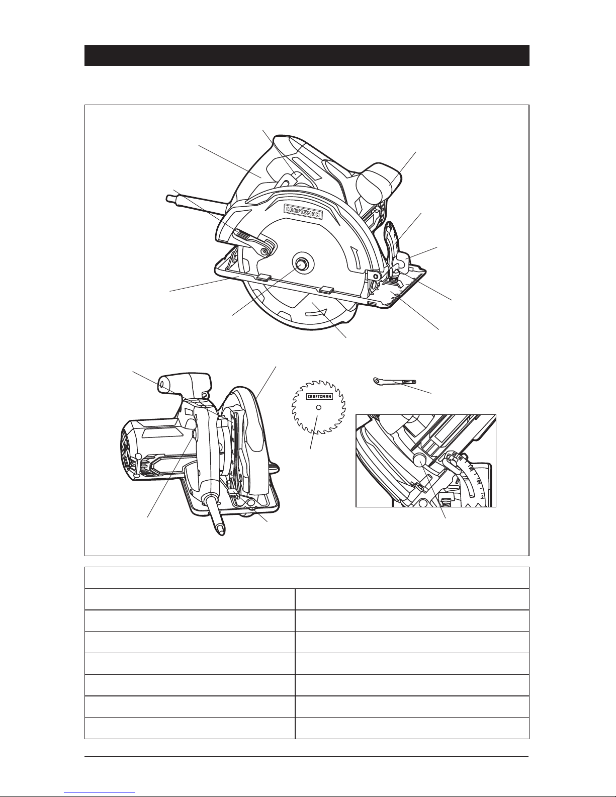
KNOW YOUR CIRCULAR SAW (Fig. 1)
Fig. 1
Trigger Switch
Rear Handle
Lower-BladeGuard Lever
Front Handle
Bevel Scale
BevelAdjustment
Knob
Edge-Guide
Lock Knob
Crosscut
Ruler
Lower Blade
Guard
Blade Screw
Base
Blade
Blade Wrench
Depth Scale
Lock-off
Button
Upper Blade Guard
Depth-of –Cut
Adjustment Lever
Spindle-Lock Button
PRODUCT SPECIFICATIONS
Rating 12 Amps
No-load Speed 5500 RPM
Blade Diameter 7 1/4 in. (184mm)
Blade Arb
or 5/8 in. (16mm)
Cutting Depth at 90°
2 1/2 in.
Cutting Depth at 45° 1 3/4 in.
Bevel Angle Adjustable 0-52°

12
ѥWARNING: The safe use of this product requires an understanding of the
information on the tool and in this operator’s manual, as well as knowledge of
the project you are attempting. Before use of this product, familiarize yourself
with all operating features and safety rules.
ERGONOMIC DESIGN
The design of the saw allows proper two-handed control when cutting. It has
been designed to be comfortable and easy to grasp.
0° TO 52° BEVEL ADJUSTMENT
The bevel adjustment lever allows you to set the circular saw for bevel cuts from
0° to 52°.
CROSSCUT RULER
The base has crosscut rulers for quick reference when making repetitive cuts.
SPINDLE-LOCK BUTTON
The spindle-lock button allows you to secure the blade when turning the
blade screw.
LOCK-OFF BUTTON
The lock-off button reduces the possibility of accidental starting.
DEPTH-OF-CUT ADJUSTMENT LEVER
The depth-of-cut adjustment lever adjusts the depth of cut a maximum of 2 1/2
in. at 90° and 1 3/4 in. at 45°.
BLADE-WRENCH STORAGE
When not in use, the blade wrench can be placed in the storage area located at
the base of the saw. Insert the blade wrench into the hole to store it.

13
ASSEMBLY
ѥWARNING: If any parts are broken or missing, do not attempt to plug or
operate the circular saw until the broken or missing parts are replaced. Failure
to do so could result in possibly serious injury.
ѥWARNING: Do not attempt to modify this circular saw or create
accessories not recommended for use with this saw. Any such alteration or
modification is misuse and could result in a hazardous condition leading to
possibly serious injury.
ѥWARNING: To prevent accidental starting that could cause serious
personal injury, always disconnect the circular saw from the power source
when changing blades.
UNPACKING
• Carefully remove the tool and any accessories from the carton. Make sure
that all items listed in the packing list are included.
• Inspect the tool carefully to make sure that no breakage or damage
occurred during shipping.
• Do not discard the packing material until you have carefully inspected and
satisfactorily operated the tool.
• If any parts are damaged or missing, please return the tool to the place
of purchase.
PACKING LIST
7 1/4 in. circular saw, blade wrench, blade and operator’s manual
14
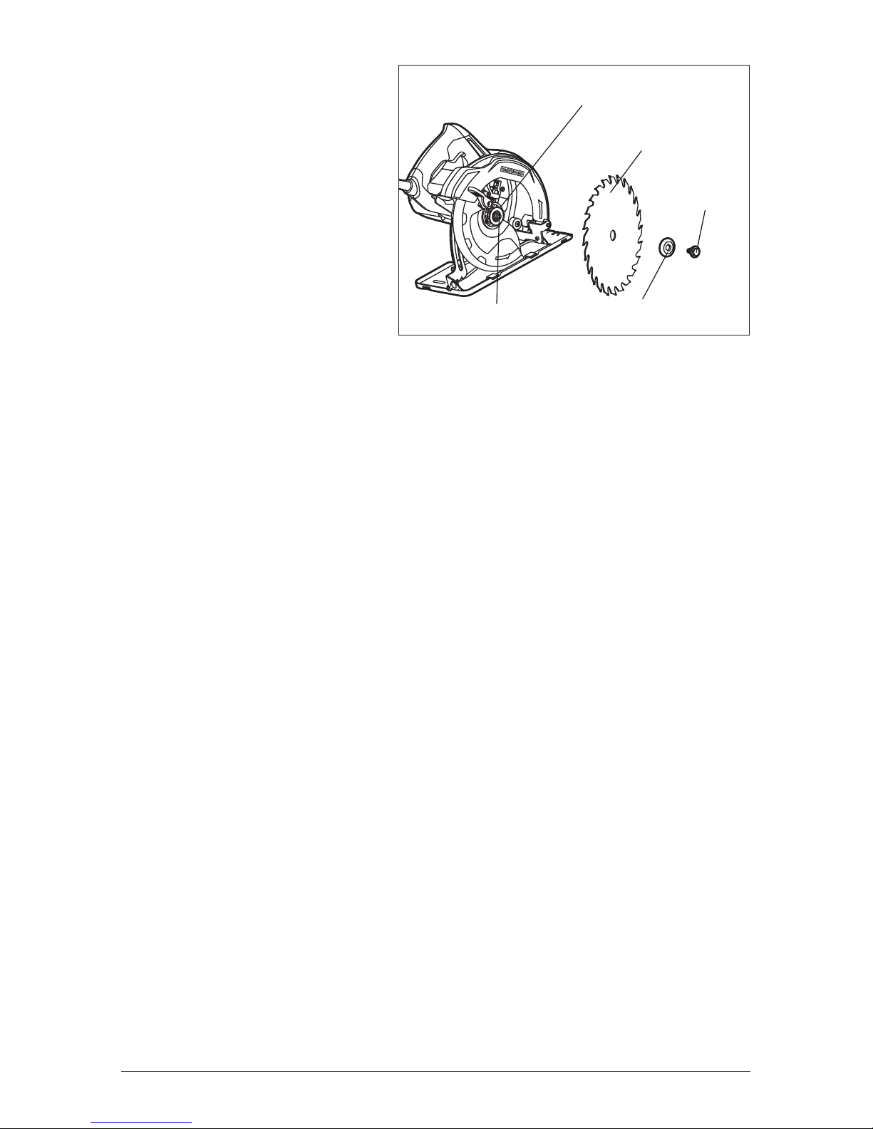
TO INSTALL THE
BLADE (Fig. 2)
ѥWARNING: Be sure to wear
protective work gloves while
handling a saw blade. The blade
can injure unprotected hands.
1. Make sure that the saw is not
connected to a power source.
2. Place the saw on its side on a
at surface.
3. Raise the depth-of-cut
adjustment lever to loosen the base. Raise the saw to its maximum height
and tighten the depth-of-cut adjustment lever. This practice permits easier
access for blade mounting.
4. Depress the spindle-lock button and place the blade wrench on the blade
screw and move it back and forth until you feel the spindle-lock button
depress further.
5. With the spindle-lock button rmly depressed, turn the blade screw
counterclockwise to loosen it.
6. Use the blade-guard lever to raise the lower blade guard and hold it in the
raised position.
7. Remove the blade screw and the outer blade washer.
8. The remaining washer is the inner bushing washer that ts around the
spindle shaft and does not need to be removed.
9. Put a drop of good-quality machine oil onto the inner bushing washer and
outer blade washer where they will contact the blade.
10. Place a new saw blade inside the lower blade guard, onto the spindle shaft
and against the inner bushing washer.
NOTICE: The teeth of the blade should point upward at the front of the saw.
11. Replace the outer blade washer.
12. Depress and hold the spindle-lock button as you replace the blade screw
and hand-tighten the screw in a clockwise direction. Use the blade wrench
to tighten the blade screw securely.
13. Return the blade wrench into the storage area.
NOTICE: Never use a blade that is too thick to allow the outer blade washer to
engage with the at side of the spindle.
Fig. 2
Inner Bushing Washer
Blade
Blade Screw
Outer Blade Washer
Spindle Shaft

15
OPERATION
SAW BLADES
The best of saw blades will not cut efciently if they are not kept clean, sharp
and properly set.
Using a dull blade will place a heavy load on the saw and increase the danger of
kickback. Keep extra blades on hand, so that sharp blades are always available.
Gum and wood pitch hardened on the blades will slow the saw down. Use gum
and pitch remover, hot water or kerosene to remove these accumulations. DO
NOT USE GASOLINE.
ѥWARNING: A blade diameter of 7 1/4 in. is the maximum blade capacity of
your saw. A blade diameter greater than 7 1/4 in. will come in contact with the
blade guards. Never use a blade that is so thick that it prevents the outer blade
washer from engaging with the flat side of the spindle. Blades that are too large
or too thick can result in an accident causing serious injury.
BLADE GUARD SYSTEM
The lower blade guard attached to your circular saw is there for your protection
and safety. It should never be altered for any reason. If it becomes damaged
or begins to return slowly or sluggishly, do not operate your saw until the blade
guard has been repaired or replaced. Always leave the guard in its correct
operating position when using the saw.
ѥDANGER: When sawing through a workpiece, the lower blade guard does
not cover the blade on the underside of the workpiece. Since the blade is
exposed on the underside of the workpiece, keep hands and fingers away from
the cutting area. Any part of your body coming in contact with a moving blade
will result in serious injury.
ѥWARNING: Never use the saw when the guard is not operating properly.
The guard should be checked for correct operation before each use. If you drop
your saw, check that the lower blade guard and bumper for damage at all depth
settings before using.
ѥWARNING: When using the saw, always stay alert and exercise control. Do
not remove the saw from the workpiece while the blade is moving.
16
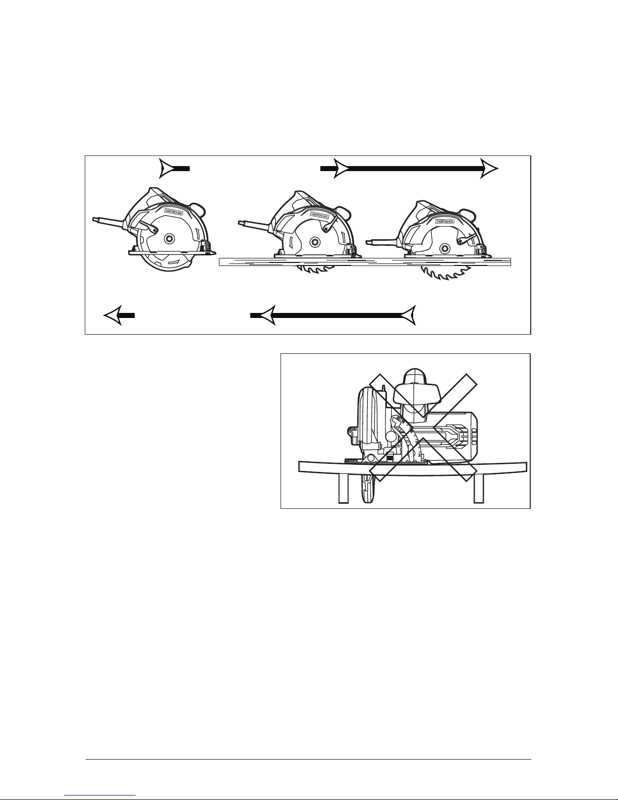
KICKBACK (Fig. 3, 4)
Kickback occurs when the blade stalls rapidly and the saw is driven back
towards you. Blade stalling is caused by any action that pinches the blade in
the wood. To avoid kickback, release the trigger switch immediately if the blade
binds or saw stalls. Kickback could cause you to lose control of the saw.
Loss of control can lead to serious injury.
Fig. 3
KICKBACK
DIRECTION OF CUT
Correct Blade Depth
Blade is Set Too Deep
To guard against kickback,
avoid dangerous practices,
such as the following:
1. Setting the blade
depth incorrectly.
2. Sawing into knots or nails in
the workpiece.
3. Twisting the blade while
making a cut.
4. Making a cut with a dull,
gummed up or improperly set blade.
5. Supporting the workpiece incorrectly (Fig. 4).
6. Forcing a cut.
7. Cutting warped or wet lumber.
8. Operating the tool incorrectly or misusing the tool.
9. Attempting to cut with blade at less than full speed.
ѥWARNING: If the blade comes in contact with the workpiece before it
reaches full speed, it could cause the saw to “kickback” towards you, which
could result in serious injury.
Wrong
Fig. 4
17
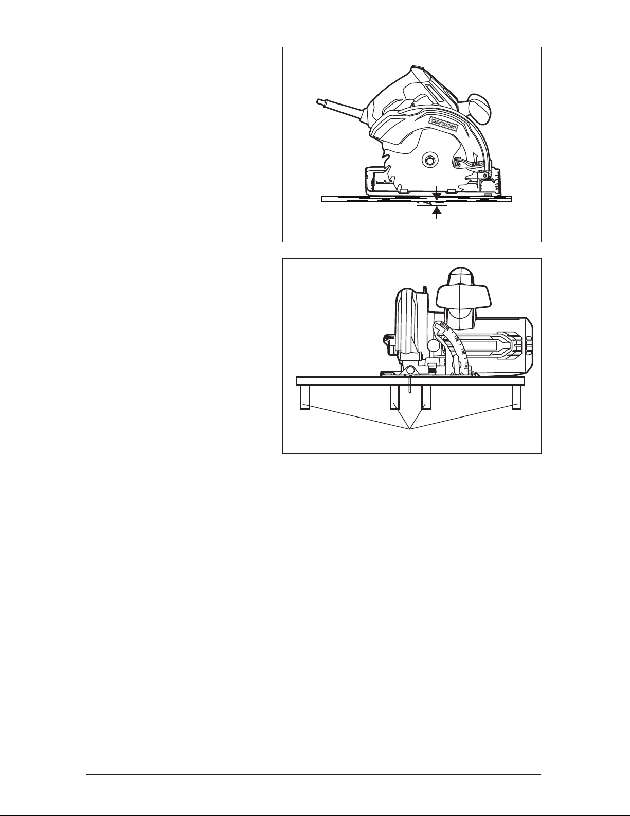
To lessen the chance
of kickback:
1. Keep the blade at the correct
depth setting. The depth
setting should not exceed 1/4
in. below the material being
cut (Fig. 5).
2. Inspect the workpiece for
knots or nails before
cutting. Never saw into a knot
or nail.
3. Make straight cuts. Always
use a straight edge guide
(available separately) when
rip cutting. This helps
prevent twisting of the blade.
4. Use clean, sharp and
properly set blades. Never
make cuts with dull blades.
5. Support the workpiece
properly before beginning
a cut (Fig. 6).
6. Use steady, even pressure
when making a cut. Never
force a cut.
7. Do not cut warped or wet lumber.
8. Hold the saw rmly with both hands and keep your body in a balanced
position so as to resist the kickback forces if kickback should occur.
ѥWARNING: To avoid kickback, release the trigger switch immediately if the
blade binds or the saw stalls. Kickback could cause you to lose control of the
saw. Loss of control can lead to serious injury.
Fig. 6
Correct Support
Fig. 5
1/4 in. maximum
18
LOCK-OFF BUTTON (Fig. 7)
The lock-off button reduces the
possibility of accidental starting.
The lock-off button is located
on the handle above the trigger
switch. The lock-off button must
be depressed before you pull the
trigger switch.
TRIGGER SWITCH (Fig. 7)
To turn the circular saw ON, depress the lock-off button, and then squeeze the
trigger switch. Do not touch the blade to the workpiece until the saw has
reached full speed.
To turn the circular saw OFF, release the trigger switch and allow it to return to
the “OFF” position.
After you release the trigger switch, allow the blade to come to a complete stop.
Do not remove the saw from the workpiece while the blade is moving.
DEPTH-OF-CUT ADJUSTMENT
Always use the correct blade-depth setting. The correct blade-depth setting for
all cuts should not be more than 1/4 in. below the material being cut. Allowing
more depth will increase the chance of kickback and cause the cut to be rough.
Your saw is equipped with a depth-of-cut scale that provides enhanced depthof-cut accuracy. The depth-of-cut scale is located on the inside back of the
upper blade guard.
TO ADJUST BLADE
DEPTH (Fig. 8)
1. Disconnect the circular saw
from the power source when
adjusting the depth of cut.
2. Raise the depth-of-cut
adjustment lever to loosen
the base.
3. Determine the desired depth
of cut.
4. Locate the depth scale on
the back of the upper
blade guard.
5. Hold the base at against the workpiece and raise or lower the saw until the
indicator aligns with the desired depth on the depth scale.
6. Tighten the depth-of-cut adjustment lever securely by lower it down.
Fig. 7
Trigger Switch
Lock-off Button
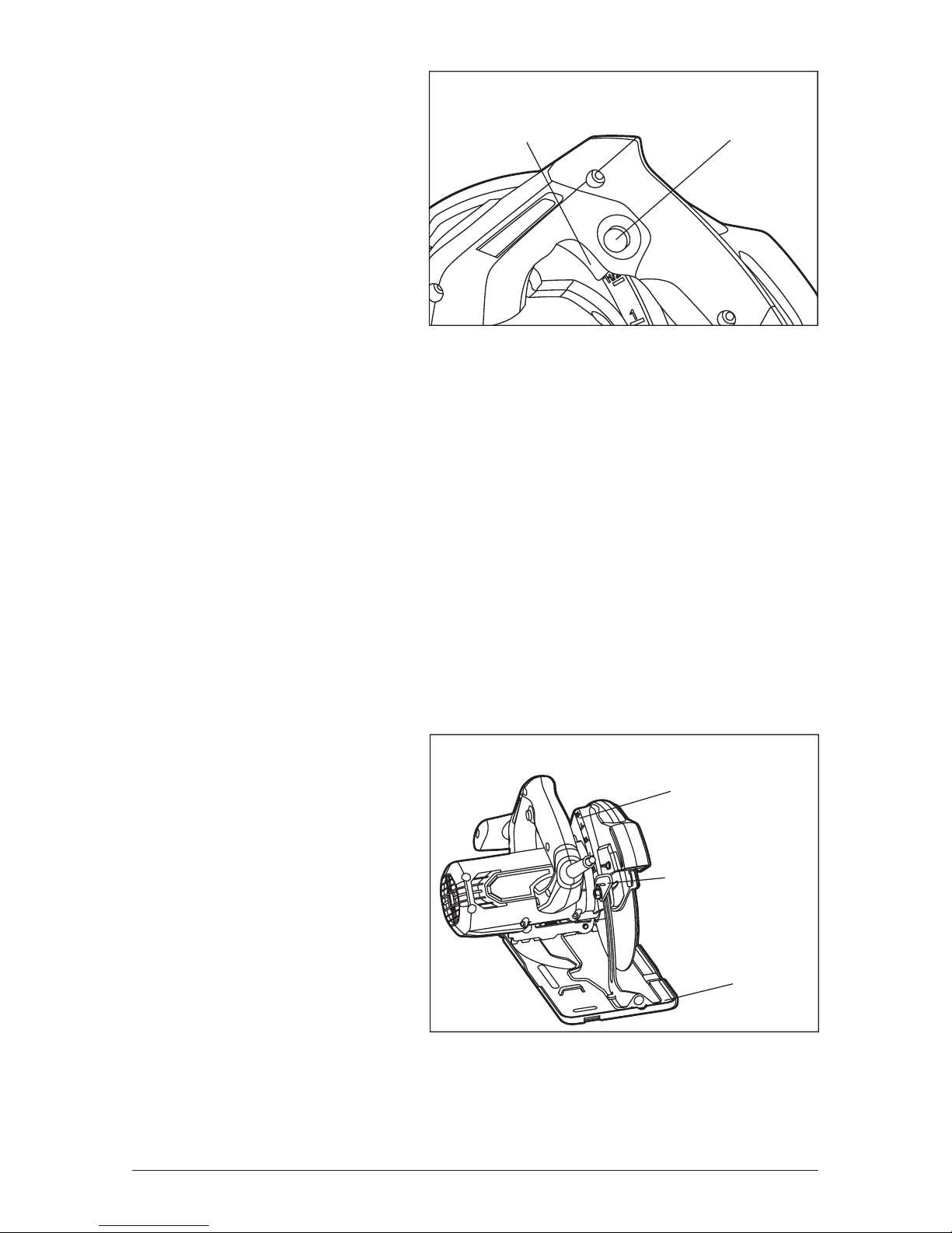
Fig. 8
Depth Scale
Depth-of-Cut
Adjustment Lever
Base
 Loading...