

Craftsman 32028084 Owner’s Manual
Product Manual
PRQFESS|ONAL
12.5 Amp, Variable Speed, 2-114
Peak HP Router Combo
with Fixed Base, Plunge Base,
and D-Handle Base
Model No. 320. 28084
= Warranty
= Safety
CAUTION! Read, understand and
follow all Safety Rules and Operating
instructions in this Manual before
using this product.
Sears, Roebuck and Co., Hoffman Estates, IL 60179
www.craftsman.com
= Assembly
= Description
= Operation
= Maintenance
= Troubleshooting

Warranty Page 2
Safety Symbols Page 3
Safety Instructions Pages 441
Unpacking Pages 1142
Description Pages 134 5
Assembly Page 16
Operation Pages 17-50
Maintenance Pages 51-52
Troubleshooting Pages 53
Accessories Pages 54-55
Parts list Pages 56-66
Sears Repair Parts Phone and Numbers Back Cover
ONE YEAR FULL WARRANTY ON CRAFTSMAN PROFESSIONAL TOOL
If this Craftsman professional tool fails to give complete satisfaction within
one year from the date of purchase, return it to any Sears store or parts &
repair center or other craftsman outlet inthe United States for free repair
(or replacement, if repair proves impossible).
This warranty does not include expendable parts such as lamps,
batteries, bits, or blades.
This warranty applies for only 90 days from the date of purchase if this
product is ever used for commercial or rental purposes
This warranty gives you specific legal rights, and you may also have other
rights which vary from state to state.
Sears, Roebuck and Co., Hoffman Estates IL 60179
,&
WARNING: Some dust created by using power tools contains chemicals
known to the stateof Californiato cause cancer and birth defects or other reproduc-
tive harm.
SAVE THESE INSTRUCTIONS!
READ ALL INSTRUCTIONS!
28084 ManuaLRevised 07-0712 Page 2

The purpose of safety symbols is to attract your attention to possible dangers. The
safety symbols, and the explanations with them, deserve your careful attention and
understanding. The symbol warnings DO NOT, by themselves, eliminate any danger.
The instructions and warnings they give are no substitutes for proper accident-pre-
vention measures.
,_ WARNING: Be sure to read and understand all safety instructions in this
manual, including all safety-alert symbols, such as "DANGER," "WARNING," and
"CAUTION," before using this router. Failure to follow all instructions listed below
may result in electric shock, fire, and/or serious personal injury.
SYMBOL MEANINGS
_. SAFETY=ALERT SYMBOL: Indicates DANGER, WARNING, OR CAUTION.
May be used in conjunction with other symbols or pictographs.
_, DANGER: Failure to obey this safety warning WILL result in death or serious
injury to you or to others. Always follow the safety precautions to reduce the risk
of fire, electric shock, and personal injury.
,_ WARNING: Failure to obey this safety warning CAN result in death or serious
injury to you or to others. Always follow the safety precautions to reduce the risk
of fire, electric shock, and personal injury.
_. CAUTION: Failure to obey this safety warning MAY result in personal injury
to you or others or property damage. Always follow the safety precautions to
reduce the risk of fire, electric shock, and personal injury.
DAMAGE PREVENTION AND INFORMATION MESSAGES
These inform user of important information and/or instructions that could lead
to equipment or other property damage if not followed. Each message is preceded
by the word "NOTE:" as in the example below:
NOTE: Equipment and/or property damage may result if these instructions are
not followed.
_, WARNING: The operation of any router can result in
W_ARYOUR foreign objects being thrown into your eyes, which can
result in severe eye damage. Before beginning power tool
operation, ALWAYS wear safety goggles or safety glasses
with side shield and a full-face shield when needed.
We recommend a Wide Vision Safety Mask for use over
eyeglasses or standard safety glasses with side shield,
available at Sears Stores or other Craftsman' Outlets.
28084 Manual Revised 07-0712 Page 3
WARNING: BE SURE to read and understand all instructions in this manual
before using this router. Failure to follow all instructions may result electric shock,
fire and/or serious personal injury.
WORK AREA SAFETY
• Keep your work area clean and well lit. Cluttered workbenches and dark
areas invite accidents.
• Do not operate power tools in explosive environments, such as in the
presence of flammable liquids, gases, or dust. Power tools create sparks,
which may ignite the dust or fumes.
- Keep bystanders, children, and visitors away while operating a power tool.
Distractions can cause you to lose control.
- Make your workshop childproof with padlocks and master switches. Lock
tools away when not in use.
• Before using your router, make sure that the work area has ample lighting
and that there are no obstructions that will interfere with its safe operation.
PERSONAL SAFETY
• Know your power tool. Read this operator's manual carefully. Learnthe
router's applications and limitations, as well as the specific, potential hazards
related to this tool.
- Stay alert, watch what you are doing, and use common sense when
operating a power tool.
• Do not use this tool while tired or under the influence of drugs, alcohol, or
medication. A moment of inattention while operating power tools may result
in serious personal injury.
• Dress properly. Do not wear loose clothing or jewelry. Pull back long hair.
Keep your hair, clothing, and gloves away from moving parts. Loose clothing
and long hair can be caught in moving parts. Air vents often cover moving
parts and should also be avoided.
• Avoid accidental starting. Be sure switch is in the "OFF" position before
plugging in the tool. Do not carry tools with your finger on the switch.
Carrying tools with your finger on the switch or plugging in tools that have the
switch in the "ON" position invites accidents.
• Remove adjusting keys or blade wrenches before turning the tool "ON."
A wrench that is left attached to a rotating part of the tool may result in
personal injury.
• Do not overreach. Keep proper footing and balance at all times. Proper foot-
ing and balance enables better control of the tool in unexpected situations.
28084 Manual Revised 07-0712 Page 4
Always secure your work. Use clamps or a vise to hold the workpiece
securely. It is safer than using your hand, and it frees both hands to operate
the tool.
• Use safety equipment. Always wear eye protection. A dust mask, non-
skid safety shoes, hardhat, and/or hearing protection must be used for
appropriate conditions.
• Do not use on a ladder or unstable support. Stable footing on a solid
surface enables better control of the tool in unexpected situations.
TOOL USE AND CARE
,_ WARNING: Be sure to read and understand all instructions before operating
this router. Failure to follow all instructions listed below may result in electric
shock, fire, and/or serious personal injury.
o Always use clamps or other practical ways to support and secure the
workpiece to a stable platform. Holding the workpiece by hand or against
your body is unstable and may lead to loss of control.
Do not force the tool. Use the correct tool and bit for your application. The
correct tool and bit will do the job better and more safely at the rate for which
it is designed.
Do not use the tool if switch does not turn it "ON" or "Off." Any tool that
cannot be controlled with the switch is dangerous and must be repaired.
• Disconnect the ptug from the power source before making any
adjustments, changing accessories, or storing the tool. Such preventive
safety measures reduce the risk of accidentally starting the tool.
• Never leave the tool running. Always turn it off. Do not leave the tool until it
comes to a complete stop.
• Store idle tools out of the reach of children and other untrained persons.
Tools are dangerous in the hands of untrained users.
o Maintain tools with care. Keep cutting tools sharp and clean. Properly
maintained tools with sharp cutting edges are less likely to bind and are
easier to control.
Check for misalignment or binding of moving parts, breakage of parts,
and any other condition that may affect the tool's operation. If damaged,
have the tool serviced before using. Many accidents are caused by poorly
maintained tools.
• Use only accessories that are recommended for this tool. Accessories
that may be suitable for one tool may become hazardous when used on
another tool.
28084 Manual Revised 07-0712 Page 5
ELECTRICAL SAFETY
_, WARNING: Do not permit fingers to touch the terminals of the plug when
installing or removing the plug from the outlet.
o Double insulated tools are equipped with a polarized plug (one blade is
wider than the other). This plug will fit in a polarized outlet only one way. If
the plug does not fit fully in the outlet, reverse the plug. If it still does not fit,
contact a qualified electrician to install a polarized outlet. Do not change the
plug in any way.
• Double insulation [] eliminates the need for the three-wire, grounded, power
cord and grounded power-supply system. Applicable only to Class II (double-
insulated) tools.
• This router motor is double insulated.
,_ WARNING: Double insulation does not take the place of normal safety
precautions when operating this tool.
• Before plugging in the tool, be sure that the outlet voltage supplied is within
the voltage marked on the tool's data plate. Do not use "AC only" rated tools
with a DC power supply.
Avoid body contact with grounded surfaces, such as pipes, radiators,
ranges, and refrigerators. There is an increased risk of electric shock if your
body is grounded.
Do not expose power tools to rain or wet conditions or use power tools
in wet or damp locations. Water entering a power tool will increase the risk of
electric shock.
• inspect tool cords for damage. Have damaged tool cords repaired at a
Craftsman Service Center. Be sure to stay constantly aware of the cord's
location and keep it well away from the moving router.
• Do not abuse the cord. Never use the cord to carry the tool or to pull
the plug from an outlet. Keep the cord away from heat, oil, sharp edges,
and moving parts. Replace damaged cords immediately. Damaged cords
increase the risk of electric shock.
EXTENSION CORDS
Use a proper extension cord. Use only cords listed by Underwriters
Laboratories (UL). Other extension cords can cause a drop in line voltage,
resulting in a loss of power and overheating of the tool.
For this tool, an AWG (American Wire Gauge) size of at least 14-gauge is
recommended for an extension cord of 25-ft. or less in length. Use 12-gauge
for an extension cord of 50-ft. Extension cords 100-ft. or longer are not
recommended.
28084 Manual Revised 07-0712 Page 6
A smaller wire gauge size has greater capacity than a larger number (14-gauge
wire has more capacity than 16-gauge wire; 12-gauge wire has more capac-
ity than 14-gauge). When in doubt, use the smaller number. When operating
a power tool outdoors, use an outdoor extension cord marked "W-A" or "W".
These cords are rated for outdoor use and reduce the risk of electric shock.
h
,_ CAUTION: Keep the extension cord clear of the working area. Position the
cord so that it will not get caught on lumber, tools, or other obstructions while
you are working with a power tool.
n
,_ WARNING: Check extension cords before each use. If damaged, replace
immediately. Never use a tool with a damaged cord, since touching the damaged
area could cause electrical shock, resulting in serious injury.
SAFETY SYMBOLS FOR YOUR TOOL
The label on your tool may include the following symbols.
V ...................................................... Volts
A....................................................... Amps
Hz ..................................................... Hertz
W...................................................... Watts
min ................................................... Minutes
"%' ............................................... Alternating current
---= .............................................. Direct current
no ................................................ No-load speed
[] .................................................. Class II construction, Double Insulated
.../min ............................................... Revolutions or Strokes per minute
.............................................. Indicates danger, warning or caution. It means
attention? Your safety is involved.
SERVICE SAFETY
• If any part of this router is missing or should break, bend, or fail in any way;
or should any electrical component fail to perform properly: shut off the
power switch, remove the router plug from the power source, and have the
missing, damaged or failed parts replaced before resuming operation.
• Tool service must be performed only at a Craftsman Parts and Repair
Center. Service or maintenance performed by unqualified personnel could
result in a risk of injury.
• Use only identical replacement parts when servicing a tool. Follow the
instructions in the maintenance section of this manual. Use of unauthorized
parts or failure to follow maintenance instructions may create a risk of electric
shock or injury.
28084 Manual Revised 07-0712 Page 7
SAFETY RULES FOR ROUTERS
_, CAUTION: Cutting bits coast after the router is switched off.
• Hold the tool by insulated gripping surfaces (handles) when performing
an operation where the cutting tool may contact hidden wiring or its own
cord. Contact with a "live" wire will make the exposed metal parts of the tool
"live" and shock the operator.
o Maintain a firm grip on the router with both hands to resist torque upon
starting the router.
• Never attempt to use the router motor without first installing it in an approved
base. Failure to heed this warning could result in personal injury and damage
to the motor.
• Make sure that the router motor does not move up or down when clamped
in a fixed base.
• Do not hold the router by hand for use in an upside-down or horizontal
position. The router motor can separate from the base if it is not properly
attached according to the instructions.
• Tighten the collet/nut securely to prevent the cutting bit from slipping. If
the collet/nut is not securely tightened, the cutting bit may detach during use,
causing serious personal injury.
• Never tighten the collet/nut without a cutting bit installed in the collet/nut.
Use clamps or other practical ways to secure and support the workpiece
to a stable platform, and hold the workpiece rigidly in position. Holding the
workpiece by hand or against your body is unstable and may lead to loss of
control.
Never hold the piece being cut in your hands or across your legs. It is
important to support and clamp the workpiece properly in order to minimize
body exposure, bit binding, and loss of control.
• Always keep the chip shield clean and in place.
• Stay alert and clear the router cutting-bit path of any obstructions before
starting the motor. Keep the cutting area clear of all foreign objects while the
router motor is running.
• Check to see that the cord will not "hang up" during routing operations.
• Make sure that the cutting bit is not in contact with the workpiece before
the switch is turned on. The bit must always be running at full speed before
contacting the workpiece.
Keep hands clear of the cutting bit when the router motor is running to
prevent personal injury.
• Provide clearance under the workpiece for the router cutting bit when
through-cutting.
28084 Manual Revised 07-0712 Page 8
o
Keep cutting pressure constant. Do not overload the motor.
o
Use only sharp cutting bits that are not chipped or cracked. Blunt cutting
bits will cause stalling and can burn the workpiece.
o Never use this router motor with a cutting bit larger than 34/2-inches in diameter.
• Always use cutting bits that are designed for this router. Never use
cutting bits that are larger in diameter than the opening in the router sub-
base. Cutting bits that have cutter diameters larger than the opening could
cause possible loss of control or create other hazardous condition that could
cause serious personal injury.
The sub-base on this router has an opening of 1=1/4 inch. To use cutting
bits with a larger diameter, install and use a sub-base with a larger diameter
opening (sold separately at Sears stores or other Craftsman outlets).
• Do not use large router cutting bits for freehand routing. Use of large
cutting bits when freehand routing could cause loss of control or create
hazardous conditions that could result in serious personal injury. If using a
router table, large bits should be used for edging only.
• Be sure the cutting bit is centered in the template guide (sold separately)
prior to template-guide applications to avoid personal injury or damage to
finished work.
• Do not remove more than 1/8 inch in a single pass. Excessive depth of
cut can result in loss of control that could result in personal injury.
Turn the router motor OFF after completing a cut, and let it come to a
complete stop before removing the router from workpiece.
• Let the router motor come to a complete stop before putting the router
down. Cutting bits coast after the power is turned off.
• Only use router tables that conform to safe woodworking practices and offer
proper guarding for the cutting bit. Use router tables that are UL classified
and identified as suitable for use with this specific router model. Failure to
comply could result in serious personal injury.
• Only use router tables with on-board, switch-controlled receptacles.
Failure to use router tables with all the appropriate safety features could
result in serious personal injury.
• Disconnect the tool from the power source before making any adjustments
or changing cutting bits.
• Be carefut not to touch the coUet/nut or cutting bit with your hands or
fingers if you are changing a bit immediately after use. The heat buildup from
cutting could cause severe burns. Always use the wrench provided.
- Avoid "climb cutting." See the OPERATION section in this manual. "Climb
cutting" increases the chance for loss of control resulting in possible serious injury.
28084 Manual Revised 07-0712 Page 9
,&
WARNING: Use of this product can generate dust containing chemicals
known to the state of California to cause cancer, birth defects or other
reproductive harm. Some examples of these chemicals are:
• Lead from lead-based paints.
• Crystalline silica from bricks and cement and other masonry products.
• Arsenic and chromium from chemically treated lumber.
Your risk from these exposures varies, depending upon how often you do this
type of work. To reduce your exposure to these chemicals:
o Work in a well-ventilated area.
• Work with approved safety equipment, such as those dust masks that are
specially designed to filter out microscopic particles.
Avoid prolonged contact with dust from power sanding, sawing, grinding, drilling,
and other construction activities. Wear protective clothing and wash exposed
areas with soap and water. Allowing dust to get into your mouth, eyes or lie on
the skin may promote absorption of harmful chemicals.
WARNING: Use of this tool can generate and/or disburse dust, which may
cause serious and permanent respiratory or other injury. Always use NIOSH/
OSHA approved respiratory protection appropriate for the dust exposure. Direct
the particles away from face and body.
ADDITIONAL RULES FOR SAFE OPERATION
,_ WARNING: Be sure to read and understand all instructions. Failure to follow
all instructions listed below may result in electric shock, fire and/or serious
personal injury.
Know your power tool Read this operator's manual carefully. Learn the
applications and limitations, as well as the specific potential hazards related
to this tool. Following this rule will reduce the risk of electric shock, fire, or
serious injury.
• Always wear safety glasses or eye shields when using this router. Everyday
eyeglasses may have impact-resistant lenses, but they are not safety
glasses.
• Protect your lungs. Wear a facemask or dust mask if the operation is dusty.
• Protect your hearing. Wear appropriate personal hearing protection
during power-tool use. Under some conditions noise from this product may
contribute to hearing loss.
• All visitors and bystanders must wear the same safety equipment that the
operator of the router should wear.
28084 Manual Revised 07-0712 Page 10
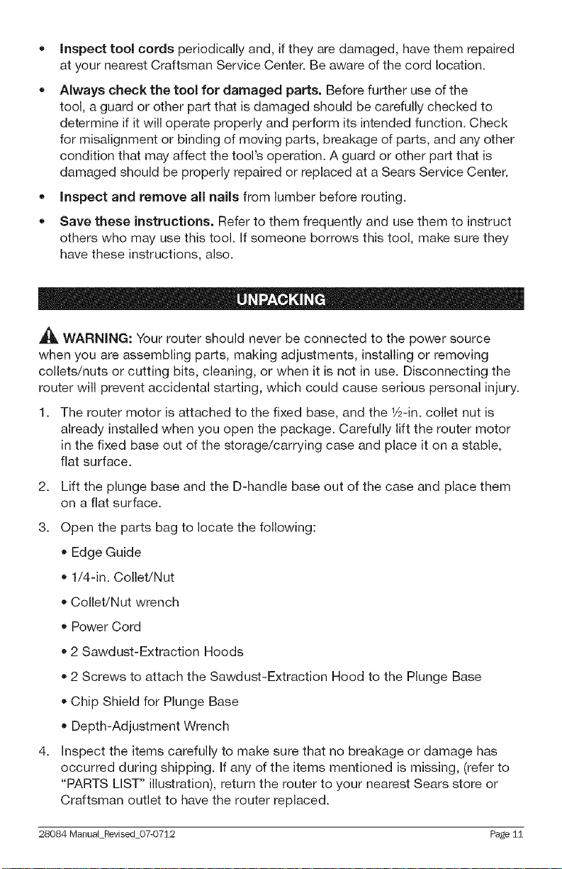
• Inspect tool cords periodically and, if they are damaged, have them repaired
at your nearest Craftsman Service Center. Be aware of the cord location.
• Always check the tool for damaged parts. Before further use of the
tool, a guard or other part that is damaged should be carefully checked to
determine if it will operate properly and perform its intended function. Check
for misalignment or binding of moving parts, breakage of parts, and any other
condition that may affect the tool's operation. A guard or other part that is
damaged should be properly repaired or replaced at a Sears Service Center.
- Inspect and remove all nails from lumber before routing.
,, Save these instructions. Refer to them frequently and use them to instruct
others who may use this tool. If someone borrows this tool, make sure they
have these instructions, also.
A
_1_ WARNING: Your router should never be connected to the power source
when you are assembling parts, making adjustments, installing or removing
collets/nuts or cutting bits, cleaning, or when it is not in use. Disconnecting the
router will prevent accidental starting, which could cause serious personal injury.
1. The router motor is attached to the fixed base, and the 1&-in. collet nut is
already installed when you open the package. Carefully lift the router motor
in the fixed base out of the storage/carrying case and place it on a stable,
flat surface.
2.
Lift the plunge base and the D-handle base out of the case and place them
on a flat surface.
3.
Open the parts bag to locate the following:
Edge Guide
• 1/4-in. Collet/Nut
• Collet/Nut wrench
• Power Cord
- 2 Sawdust-Extraction Hoods
• 2 Screws to attach the Sawdust-Extraction Hood to the Plunge Base
• Chip Shield for Plunge Base
• Depth-Adjustment Wrench
4.
Inspect the items carefully to make sure that no breakage or damage has
occurred during shipping. If any of the items mentioned is missing, (refer to
"PARTS LIST" illustration), return the router to your nearest Sears store or
Craftsman outlet to have the router replaced.
28084 Manual Revised 07-0712 Page 11
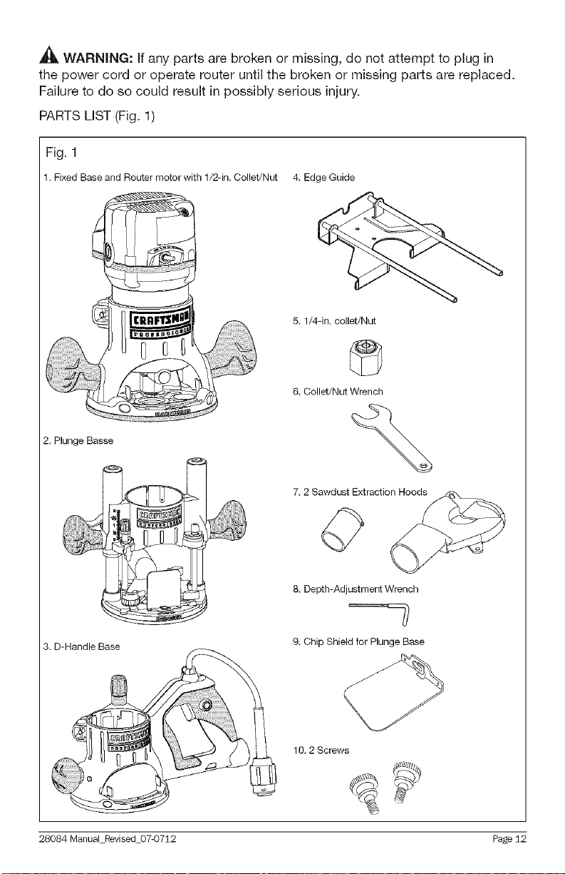
_h, WARNING: If any parts are broken or missing, do not attempt to plug in
the power cord or operate router until the broken or missing parts are replaced.
Failure to do so could result in possibly serious injury.
PARTS LIST (Fig. 1)
Fig. 1
1. Fixed Base and Router motor with 1/2-in. Collet/Nut 4. Edge Guide
5. 1/4-in. collet/Nut
6. Collet/Nut Wrench
2. Plunge Basse
7.2 Sawdust Extraction_
8. Depth-AdjustmentWrench
3. D-Handle Base
28084 Manual Revised 07-0712 Page 12
9. Chip Shield for Plunge Base
10.2 Screws
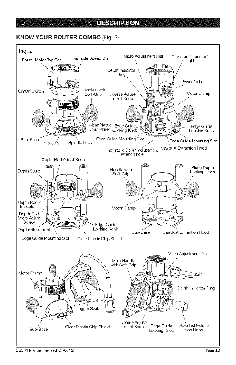
KNOW YOUR ROUTER COMBO (Fig. 2)
Fig. 2
Router Motor Top Cap
On/Off Handles with
Sub Base
Depth _
Depth Rod / /_
Indicator /I
Depth-Rod _
Micro Adjust
Screw
Depth-Stop Turret
Edge Guide Mounting Slot Clear Plastic Chip Shield
Collet/Nut Spindle Lock
Depth-Rod Adjust Knob
Variable Speed Dial Micro Adjustment Dial
/
Depth Indicatol
Soft-Grip
Edge Guide Mounting Slot
Integrated Depth-adjustment
Ring
\
Coarse Adjust-
Wrench hole
Sub-Base
"Live Tool Indicator"
Light
Power Outlet
Motor Clamp
Edge Guide
Locking Knob
Edge Guide Mounting Slot
Sawdust Extraction Hood
igD__ePthr
Sawdust Extraction Hood
Micro Adjustment Dial
Depth Indicator Ring
Motor_Clam
Coarse Adjust-
Sub-Base Clear Plastic Chip Shield
28084 Manual Revised 07-0712 Page 13
ment Knob Edge Guide
Locking Knob
Sawdust Extrac-
tion Hood

PRODUCT SPECiFiCATiONS
Rating 12.5 Amps
No load Speed 12000-25000RPM
Peak HP 2-1/4
Input 120V, 60Hz AC
Collets/Nuts and Cutting Bit Shank Diameters 1/4 in., 1/2 in.
Fixed Base Diameter 6 inches
Plunge Base Diameter 6 -11/16 inches
D-Handle Base Diameter 6 inches
Sub-Base Opening (Diameter for cutting bit use) 1-1/4 inches
Sub-Base Thickness 0.23 inches (6mm)
Fixed Base Depth of Cut 1-3/4 inches (45mm)
Plunge Base Depth of Cut 2-1/8 inches (55mm)
D-handle Base Depth of Cut 1-3/4-inches (45mm)
NOTE: Before attempting to use your router, familiarize yourself with all of the
operating features and safety requirements.
Your router has a precision-built electric router motor, and it should be connected
only to a 120-volt, 60-Hz AC ONLY power supply (normal household current).
Do not operate on direct current (DC). This large voltage drop will cause a loss
of power and the router motor will overheat. If the router does not operate when
plugged into a correct 120-volt, 60-Hz AC ONLY outlet, check the power supply.
This router has a 10-ft, 2-wire power cord (no adapter needed).
This Router Combo has the following features:
1. 12.5 Amp, 244 Peak HP, Variable Speed Router motor, which runs at 12,000
to 25,000 RPM (no-load speed).
2. Variable Speed Dial for matching the speed to the workpiece material and bit size.
3. Electronic-Feedback Circuitry maintains constant speed under load for a
quality finish in all materials.
4. Soft-start feature minimizes the torque twist common with larger router
motors by limiting the speed at which the router motor starts. This also
increases the motor's life.
5. Quick-Clamp System allows the router motor to be changed among Fixed,
Plunge, and D-Handle bases without tools.
6. Fixed Base and D-Handle bases feature coarse and fine depth adjustments
for accurate set-ups.
28084 ManuaLRevised 07-0712 Page 14

7. Plunge Base features fine and micro depth-rod adjustments with turret stops
for precise set-ups and repetitive cutting.
8. Smooth plunge action lowers the bit into the workpiece at 90° for accurate cutting.
9. 3-position auxiliary handle on the D-handle base for positioning to
individual preference.
10. Spindle Lock for easy, one-wrench bit changes.
11.1/4-inch and 1/2-inch Self-Releasing Collets/Nuts for use with a wide variety
of 1/4-in. and 1/2-in. router bits, sold separately.
12. Detachable power cord: replaceable to prolong tool life and removable for
easy carrying and storage.
13. Ball Bearings throughout the motor for smooth, efficient operation and long life.
14. Ergonomically designed handles with soft grip on the three router bases for
comfort and maximum control with less vibration.
15. Large base openings and large chip shields on the three bases, combined
with 3 LED Worklights on the Router motor to provide high visibility of the bit
and the workpiece.
16. Durable, non-marring sub-bases glide smoothly over the workpiece. The
sub-bases have a cutter-bit opening of 1-1/4 in.
17. Router motor constructed of high-density nylon and precision-milled cast
aluminum for strength and exact fit into bases.
18. Bases constructed of magnesium to provide lightweight, durability, and stability.
19. Impact-resistant router-motor top cap and handles on bases help protect the
tool from damage.
20. Heavy-duty Edge Guide for routing applications such as decorative edging,
grooving, dadoing, slotting, and straightedge planing/trimming.
21. Conveniently located On/Off Toggle Switch is front mounted for added
visibility and easy access.
22. Sawdust-Extraction Hood allows bases to attach to 1-1/4-inch vacuum hose
attachment, sold separately.
23. LiveTool Indicator Ught shines green when the router is plugged into a power source.
24. Replaceable Brushes (sold separately) for dependable service.
25. Includes impact-resistant case for easy carrying and storage.
26. Table Mounting Holes on bases for mounting the router to a router table
(available separately).
27. Integrated depth-adjustment-wrench opening for adjusting the depth of cut
from above a routing table with the depth-adjustment wrench.
28084 ManuaLRevised 07-0712 Page 15

NOTE: This tool is shipped completely assembled. To change the router motor
from one base to another, install or remove cutting bits, add accessories such as
sawdust ejection hoods for hook-up to vacuums, or install the heavy-duty edge
guide, see the following instructions.
28084 Manual Revised 07-0712 Page 16
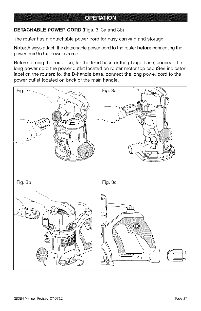
DETACHABLE POWER CORD (Figs. 3, 3a and 3b)
The router has a detachable power cord for easy carrying and storage.
Note: Always attach the detachable power cord to the router before connecting the
power cord to the power source.
Before turning the router on, for the fixed base or the plunge base, connect the
long power cord the power outlet located on router motor top cap (See indicator
label on the router); for the D-handle base, connect the long power cord to the
power outlet located on back of the main handle.
Fig. 3_ \_ Fig. 3a
"t
\
Fig. 3b Fig. 3c
28084 ManuaLRevised 07-0712 Page 17
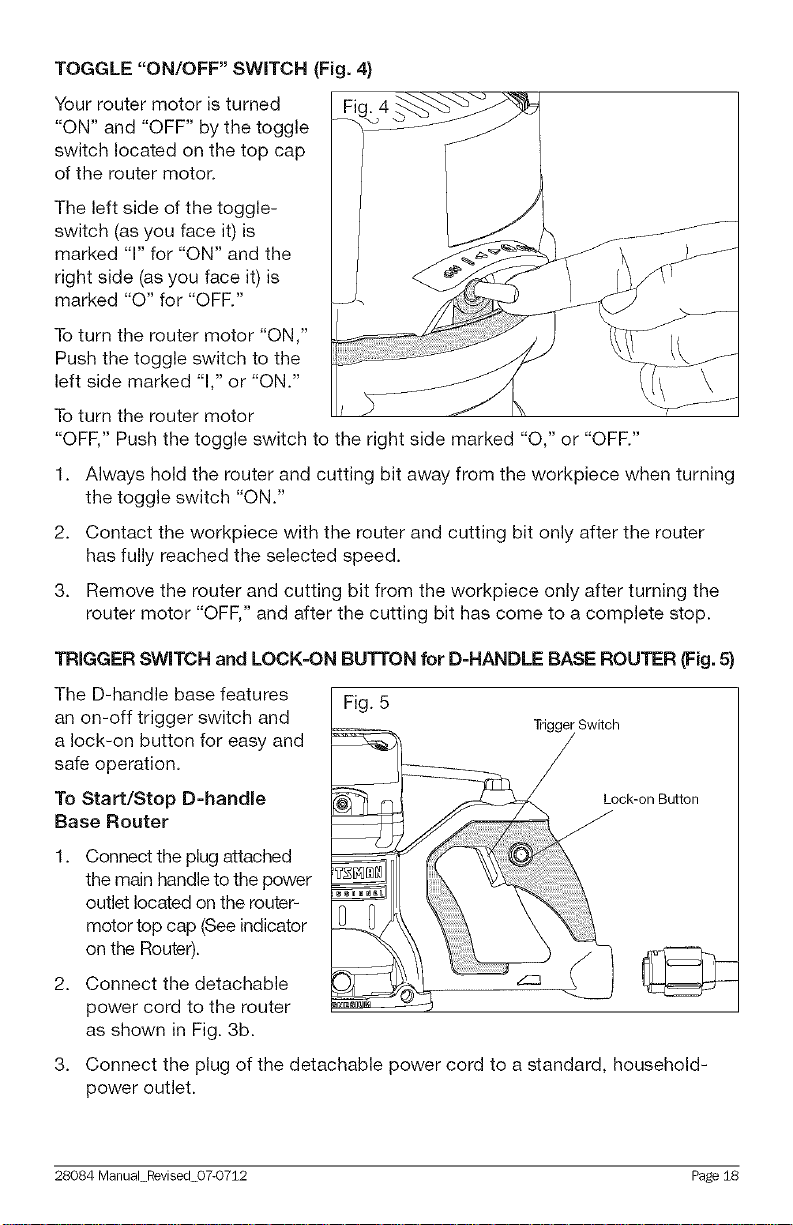
TOGGLE "ON/OFF" SWITCH (Fig. 4)
Your router motor is turned
"ON" and "OFF" by the toggle
switch located on the top cap
of the router motor.
The left side of the toggle-
switch (as you face it) is
marked "1" for "ON" and the
right side (as you face it) is
marked "0" for "OFF."
Toturn the router motor "ON,"
Push the toggle switch to the
left side marked "1," or "ON."
Toturn the router motor
"OFF," Push the toggle switch to the right side marked "0," or "OFF."
1. Always hold the router and cutting bit away from the workpiece when turning
the toggle switch "ON."
2. Contact the workpiece with the router and cutting bit only after the router
has fully reached the selected speed.
3. Remove the router and cutting bit from the workpiece only after turning the
router motor "OFF," and after the cutting bit has come to a complete stop.
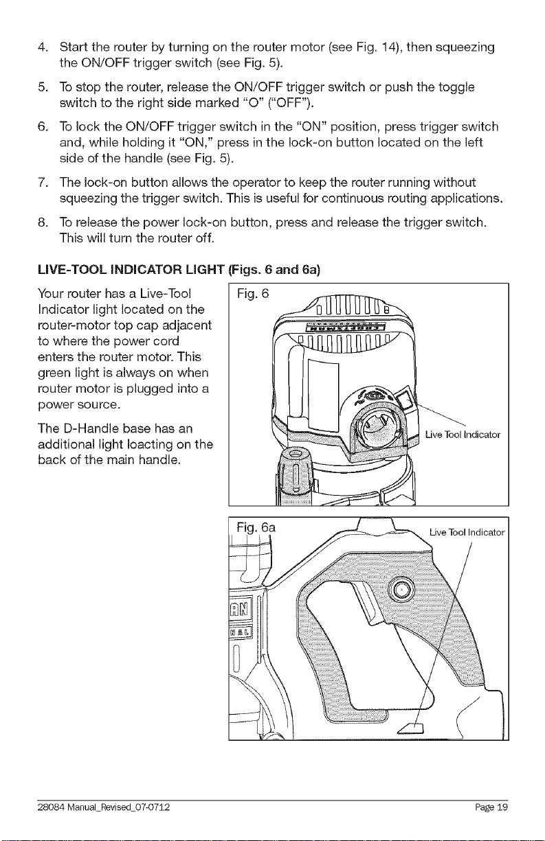
TRIGGER SWITCH and LOCK=ON BUTTON for D=HANDLE BASE ROUTER (Fig. 5)
The D-handle base features
Fig. 5
an on-off trigger switch and
a lock-on button for easy and
safe operation.
To Start/Stop D=handie
Base Router
Connect the plug attached
the main handle to the power
outlet located on the router-
motor top cap (See indicator
on the Router).
Connect the detachable
2_
power cord to the router
as shown in Fig. 3b.
3_
Connect the plug of the detachable power cord to a standard, household-
power outlet.
28084 Manual Revised 07-0712 Page 18
4. Start the router by turning on the router motor (see Fig. 14), then squeezing
the ON/OFF trigger switch (see Fig. 5).
5. To stop the router, release the ON/OFF trigger switch or push the toggle
switch to the right side marked "0" ("OFF").
6. To lock the ON/OFF trigger switch in the "ON" position, press trigger switch
and, while holding it "ON," press in the lock-on button located on the left
side of the handle (see Fig. 5).
7. The lock-on button allows the operator to keep the router running without
squeezing the trigger switch. This is useful for continuous routing applications.
8. To release the power lock-on button, press and release the trigger switch.
This will turn the router off.
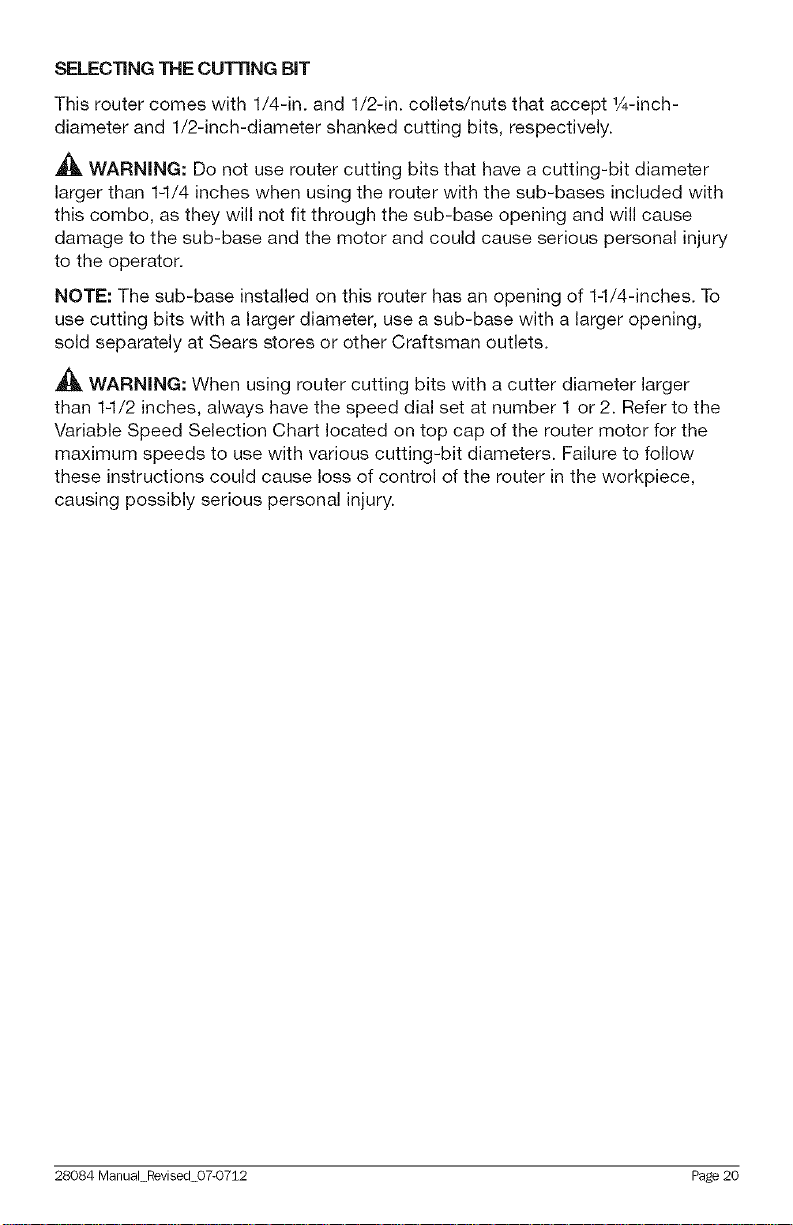
LiVE=TOOL iNDiCATOR LIGHT (Figs. 6 and 6a}
Your router has a Live-Tool Fig. 6
Indicator light located on the
router-motor top cap adjacent
to where the power cord
enters the router motor. This
green light is always on when
router motor is plugged into a
power source.
The D-Handle base has an
Live Tool Indicator
additional light Ioacting on the
back of the main handle.
Fig. 6a
28084 ManuaLF_vised 07-0752 Page 19
Live Tool Indicator
SELECTING THE CUTTING BiT
This router comes with 1/4-in. and 1/2-in. collets/nuts that accept 1A-inch-
diameter and 1/2-inch-diameter shanked cutting bits, respectively.
,_ WARNING: Do not use router cutting bits that have a cutting-bit diameter
larger than 1-I/4 inches when using the router with the sub-bases included with
this combo, as they will not fit through the sub-base opening and will cause
damage to the sub-base and the motor and could cause serious personal injury
to the operator.
NOTE: The sub-base installed on this router has an opening of 14/4-inches. To
use cutting bits with a larger diameter, use a sub-base with a larger opening,
sold separately at Sears stores or other Craftsman outlets.
WARNING: When using router cutting bits with a cutter diameter larger
than 1-1/2 inches, always have the speed dial set at number 1 or 2. Refer to the
Variable Speed Selection Chart located on top cap of the router motor for the
maximum speeds to use with various cutting-bit diameters. Failure to follow
these instructions could cause loss of control of the router in the workpiece,
causing possibly serious personal injury.
28084 ManuaLRevised 07-0712 Page 20
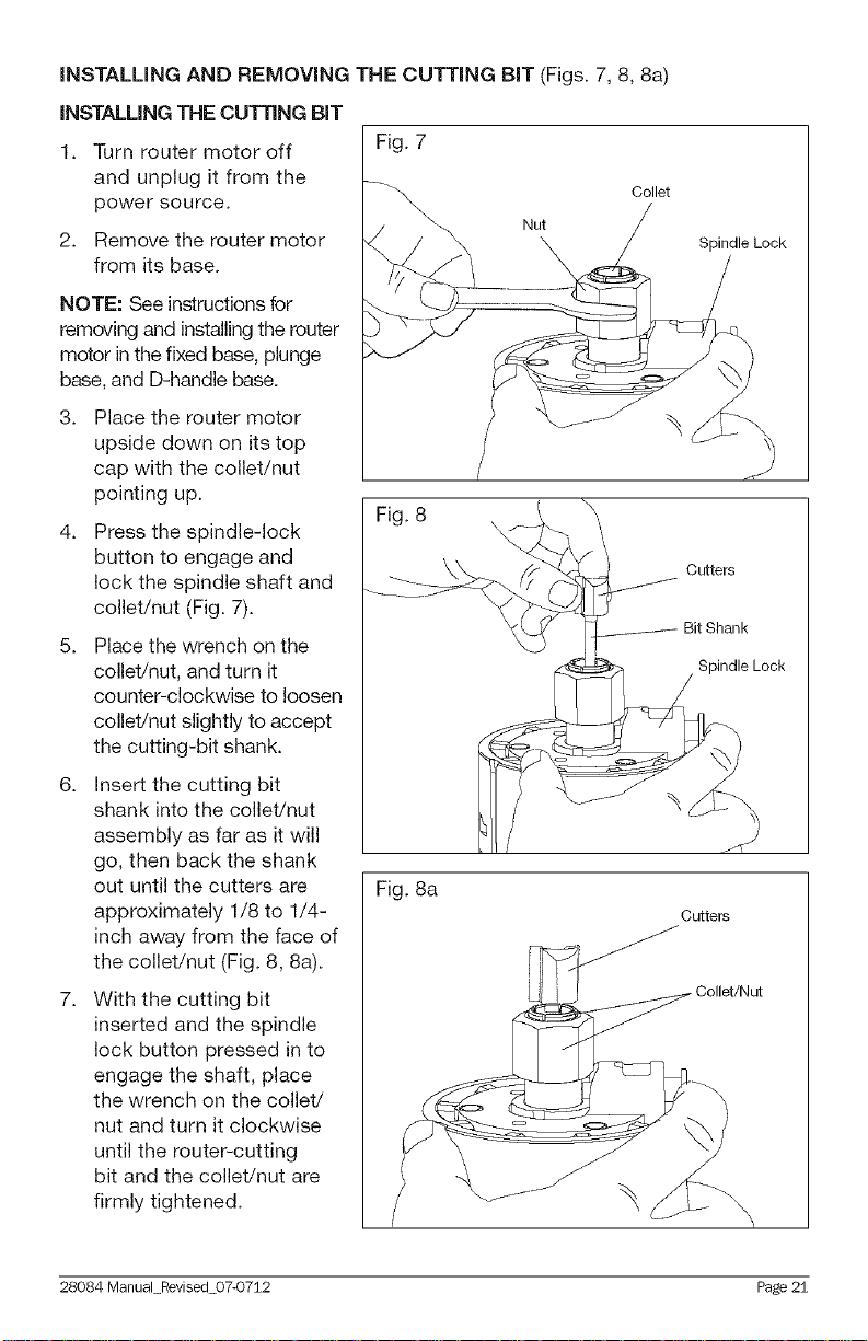
iNSTALLiNG AND REMOVING THE CUTTING BiT (Figs. 7, 8, 8a)
iNSTALLiNG THE CUTTING BiT
1. Turn router motor off
and unplug it from the
power source.
2. Remove the router motor
from its base.
NOTE: See instructions for
removing and installing the router
motor in the fixed base, plunge
base, and D-handle base.
3. Place the router motor
upside down on its top
cap with the collet/nut
pointing up.
4. Press the spindle-lock
button to engage and
lock the spindle shaft and
collet/nut (Fig. 7).
5. Place the wrench on the
collet/nut, and turn it
counter-clockwise to loosen
collet/nut slightly to accept
the cutting-bit shank.
Fig. 7
Collet
Nut
\
Fig. 8 /
Spindle Lock
Cutters
Bit Shank
Spindle Lock
6. Insert the cutting bit
shank into the collet/nut
assembly as far as it will
go, then back the shank
out until the cutters are
approximately 1/8 to 1/4-
inch away from the face of
the collet/nut (Fig. 8, 8a).
7. With the cutting bit
inserted and the spindle
lock button pressed in to
engage the shaft, place
the wrench on the collet/
nut and turn it clockwise
until the router-cutting
bit and the collet/nut are
firmly tightened.
28084 Manual Revised 07-0712 Page 21
Fig. 8a
Cutters
_ Collet/Nut
 Loading...