

Page 1
Owner's Manual
10 in.
TABLE SAW
Model No.
315.228110
Save this manual for
future reference.
^ CAUTION: Read and follow all
Safety Rules and Operating
Instructions before first use of this
product.
Customer Help Line: 1-800-932-3188
Sears. Roebuck and Co., Hoffman Estates, IL 60179 USA
Visit the Craftsman web page:
972000-713
1-00
www.sears.com/craftsman
Safety
Features
Assembly
Operation
• Maintenance
• Parts List
( $ )
Page 2
WARRANTY
FULL ONE YEAR WARRANTY ON CRAFTSMAN TABLE SAW
If this CRAFTSMAN Table Saw fails due to a defect in material or workmanship within one year from the date of
purchase, Sears will repair it, free of charge.
Contact a Sears Service Center for repair.
If this product is used for commercial or rental purposes, this warranty applies only for 90 days from the date of
purchase.
This warranty gives you specific legal rights, and you may also have other rights which vary from state to state.
Sears, Roebuck and Co., Dept. 817WA, Hoffman Estates, IL 60179
INTRODUCTION
Your saw has many features for making cutting operations more pleasant and enjoyable. Safety, performance
and dependability have been given top priority in the design of this saw making it easy to maintain and operate.
CAUTION: Carefully read through this entire owner’s manual before using your new saw. Pay close
attention to the Rules For Safe Operation, and all Safety Alert Symbols, including Danger, Warning and
Caution. If you use your saw properly and only for what it is intended, you will enjoy years of safe, reliable
service. ’
Look for this symbol to point out important safety precautions. It means attention!!! Your safety is involved.
WARNING:
The operation of any power tool can result in foreign objects being thrown into your eyes,
which can result in severe eye damage. Before beginning power tool operation, always
wear safety goggles or safety glasses with side shields and a full face shield when needed.
We recommend a Wide Vision Safety Mask for use over eyeglasses or standard safety
glasses with side shields, available at Sears Retail Stores.
TABLE OF CONTENTS
Warranty and Introduction....................................................................................................................................
Table Of Contents.............................................................................................................................................. 2-3
Rules For Safe Operation................................................................................................................................. 4.0
Electrical................................................................................................................................................................ y
Glossary and Product Specifications..................................................................................................................
Unpacking and Accessories............................................................................................................................. g
Loose Parts List............................................................................................................................................10^11
Tools Needed...................................................................................................................................................... .|2
Features.......................................................................................................................................................... 13-15
Assembly....................................................................................................................................16-20
A. Assembly Of Leg Stand, Storage Brackets, and Mounting To Saw
Assembling Leg Stand........................................................................................................................................................ .|0
Assembling Storage Brackets................................................................................................................... , '........................17
Mounting The Leg Stand On The Table Saw Base...................................................17
B. Assembly Of Rails, Tables, and Fences........................................................................................................................18-19
To Install Front and Back Rail......................................................................................................................................... 18
To Install Miter Table and Fence.......................................................................................................................................... 18
To Install Accessory Table and Rip Fence.........................................................................................................................19
...........................................................................
16-17
...
...
CRRFTSMHN* TABLE SAW 315.228110
Page 3

TABLE OF CONTENTS (CONT.)
C. Blade Check and Blade Guard Assembly...................................................................................................................19-20
To Check Saw Blade Installation ..........................................................................................................................................19
To Install Blade Guard............................................................................................................................................................20
Operation............................................................................................................................................................................ 21-33
A. General Information..............................................................................................................................................................21
Grounding..............................................................................................................................................................................21
Types Of Cuts.....................................................................................................................................................................21-22
Cutting Tips............................................................................................................................................................................22
B. Settings and Adjustments................................................................................................................................................23-28
To Remove The Blade...........................................................................................................................................................23
To Check Replace Or Adjust The Riving Knife and Blade Guard Assembly...................................................................24
1. Remove The Throat Plate.........................................................................................................................................24
To Reduce The Risk Of Kickback........................................................................................................................................25
To Avoid Kickback.................................................................................................................................................................25
To Make A Push Stick...........................................................................................................................................................26
Featherboard..........................................................................................................................................................................26
How To Make A Featherboard.............................................................................................................................................26
How To Mount A Featherboard............................................................................................................................................26
To Adjust Blade Depth...........................................................................................................................................................27
To Adjust Blade Angle...........................................................................................................................................................27
To Set The Scale To The Blade...........................................................................................................................................27
To Lock Miter Table...............................................................................................................................................................28
C. Making Cuts......................................................................................................................................................................28-33
To Make A Straight Cross Cut........................................................................................................................................28-29
To Make A Miter Cut..............................................................................................................................................................29
To Make A Straight Rip Cut..................................................................................................................................................29
To Make A Bevel Cross Cut...................................................................................................................................................30
To Make A Bevel Rip Cut................................................................................................................................................30-31
To Make A Compound Miter Cut.......................................................................................................................................... 31
To Make A Large Panel Cut
To Make Non-Through Cuts..................................................................................................................................................32
To Make Dado Cuts................................................................................................................................................................33
Maintenance...........................................................................................................................................................................34-36
A. General Maintenance.............................................................................................................................................................34
B. Specific Table Saw Maintenance...................................................................................................................................34-36
To Set Blade At 0 Or 45 Degrees..........................................................................................................................................34
To Check The Alignment Of The Rip Fence To The Blade...............................................................................................35
To Adjust The Bevel Locking Lever.......................................................................................................................................35
To Align The Miter Locking Clamps...................................................................................................................................... 36
To Adjust The Front and Rear Rail Clamps........................................................................................................................36
To Adjust The Accessory Table.............................................................................................................................................36
Sliding Miter Table Assembly...............................................................................................................................................37-41
Checking Sliding Miter Table Assembly.....................................................................................................................................38
To Check Miter Base Parallelism..........................................................................................................................................38
To Check Miter Fence Alignment..........................................................................................................................................39
Making Adjustments To Sliding Miter Table Assembly.....................................................................................................39-41
To Adjust The Miter Base.......................................................................................................................................................39
To Adjust The Miter Fence.....................................................................................................................................................40
To Adjust Quick Stop.............................................................................................................................................................41
Lubrication................................................................................................................................................................................... 42
Locker Bracket Assembly.............................................................................................................................................................42
Tilt / Elevating Mechanism...........................................................................................................................................................42
Troubleshooting.................................................................................................................................................................... 44-45
Exploded View and Repair Parts List...................................................................................................................................46-53
Parts Ordering / Service...............................................................................................................................................back page
......................
.■........................................................................................................................31
CRHFTSMRN' TABLE SAW 315.22S110
Page 4

RULES FOR SAFE OPERATION
The purpose of safety symbols is to attract your attention to possible dangers. The safety symbols, and the
explanations with them, deserve your careful attention and understanding. The safety warnings do'not by
themselves eliminate any danger. The instructions or warnings they give are not substitutes for proper accident
prevention measures.
SYMBOL
A
A
A
A
Note:
MEANING
SAFETY ALERT SYMBOL
Indicates danger, warning, or caution. May be used in conjunction with other symbols or
pictographs.
DANGER: Failure to obey a safety warning will result in serious injury to yourself or to others.
Always follow the safety precautions to reduce the risk of fire, electric shock and personal injury.
WARNING: Failure to obey a safety warning can result in serious injury to yourself or to others.
Always follow the safety precautions to reduce the risk of fire, electric shock and personal injury.
CAUTION: Failure to obey a safety warning may result in property damage or personal injury to
yourself or to others. Always follow the safety precautions to reduce the risk of fire, electric shock
and personal injury.
Advises you of information or instructions vital to the operation or maintenance of the equipment.
IMPORTANT
Servicing requires extreme care and knowledge of the
system and should be performed only by a qualified
service technician. For service we suggest you return
the tool to your nearest Sears store or repair center.
Always use original factory replacement parts when
servicing.
WARNING: Do not attempt to operate this tool
until you have read thoroughly and understand
completely all instructions, safety rules, etc.
contained in this manual. Failure to comply can
result in accidents involving fire, electrical shock,
or serious personal injury. Save the owner’s
manual and review frequently for continuing safe
operation, and instructing others who may use
this tool.
READ ALL INSTRUCTIONS
■ KNOW YOUR POWER TOOL. Read the owner's
manual carefully. Learn the saw’s applications
and limitations as well as the specific potential
hazards related to this tool.
■ DO NOT USE IN DANGEROUS ENVIRON
MENT. Do not use power tools near gasoline or
other flammable liquids, in damp or wet loca
tions, or expose them to rain. Keep the work
area well lit.
■ MAKE WORKSHOP CHILD-PROOF with
padlocks and master switches or by removing
starter keys.
■ KEEP CHILDREN AND VISITORS AWAY. All
visitors should wear safety glasses and be kept a
safe distance from work area. Do not let visitors
contact tool or extension cord white operating.
■ KEEP THE WORK AREA CLEAN. Cluttered
work areas and work benches invite accidents.
DO NOT
saw while it is in operation.
leave tools or pieces of wood on the
MAINTAIN TOOLS WITH CARE. Keep tools
sharp and clean for better and safer perfor
mance. Follow instructions for lubricating and
changing accessories,
USE THE RIGHT TOOL FOR THE JOB. Do not
force the tool or attachment to do a job it was not
designed for. Use it only the way it was intended.
DRESS PROPERLY. Do not wear loose clothing,
gloves, neckties, rings, bracelets, or other
jewelry. They can get caught and draw you into
moving parts. Rubber gloves and nonslip foot
wear are recommended. Also wear protective
hair covering to contain long hair.
ALWAYS WEAR SAFETY GLASSES WITH
SIDE SHIELDS. Everyday eyeglasses have only
impact-resistant lenses; they are NOT safety
glasses.
NEVER STAND ON TOOL. Serious injury could
occur if the tool is tipped or if the blade is unin
tentionally contacted.
CRRFTSMRN' TABLE SAW 315.228110
Page 5

RULES FOR SAFE OPERATION (Continued)
■ DO NOT OVERREACH. Keep proper footing and
balance at all times.
■ SECURE WORK. Use clamps or a vise to hold
work when practical. It’s safer than using your
hand and frees both hands to operate tool.
■ USE THE PROPER EXTENSION CORD. Make
sure your extension cord is in good condition.
Use only a cord heavy enough to carry the
current your product will draw. An undersized
cord will cause a drop in line voltage resulting in
loss of power and overheating. A wire gage size
(A.W.G.) of at least 14 is recommended for an
extension cord 25 feet or less in length. If in
doubt, use the next heavier gage. The smaller
the gage number, the heavier the cord.
■ AVOID ACCIDENTAL STARTING. Be sure
switch is off when plugging in.
■ REMOVE WRENCHES AND ADJUSTING
KEYS. Get in the habit of checking - before
turning on tool - that hex keys and adjusting
wrenches are removed from tool.
■ CHECK DAMAGED PARTS. Before using the
tool again, check any damaged parts, including
guards, for proper operation and performance.
Check alignment of moving parts, binding of
moving parts, breakage of parts, saw stability,
mounting and any other conditions that may
affect its operation. A damaged part must be
properly repaired or replaced by a qualified
service technician at a Sears store or repair
center to avoid risk of personal injury.
■ USE ONLY CORRECT BLADES. Use the right
blade size, style and cutting speed for the
material and the type of cut. Blade teeth should
point down toward the front of the table.
■ USE RECOMMENDED ACCESSORIES. Using
improper accessories may risk injury.
■ USE ONLY SEARS REPLACEMENT PARTS.
All repairs, whether electrical or mechanical,
should be made by a qualified service technician
at a Sears store or repair center.
■ KEEP GUARDS IN PLACE and in good working
order. This includes the blade guard, riving knife,
and anti-kickback pawls.
■ CHECK DIRECTION OF FEED. Feed work into
a blade or cutter against the direction of rotation
of the blade or cutter only.
■ DISCONNECT ALL TOOLS. When not in use,
before servicing, or when changing attachments,
blades, bits, cutters, etc., all tools should be
disconnected from power supply.
■ DO NOT FORCE THE TOOL. It will do the job
better and more safely at the rate for which it
was designed.
■ NEVER LEAVE TOOL RUNNING UNAT
TENDED. TURN THE POWER OFF. Do not
leave tool until it comes to a complete stop.
■ BEFORE DISCONNECTING THE MOTOR;
unplug the saw from power supply.
^ WARNING: When servicing, use only identical
Craftsman replacement parts. Use of any other
parts may create a hazard or cause product
damage.
■ NEVER USE THIS TOOL IN AN EXPLOSIVE
ATMOSPHERE. Normal sparking of the motor
could ignite fumes.
■ MAKE SURE THE WORK AREA HAS AMPLE
LIGHTING to see the work and that no obstruc
tions will interfere with safe operation BEFORE
performing any work using this tool.
■ DO NOT USE TOOL IF SWITCH DOES NOT
TURN IT ON AND OFF. Have defective switches
replaced by a qualified service technician at a
Sears store or repair center.
■ GUARD AGAINST ELECTRICAL SHOCK by
preventing body contact with grounded surfaces
such as pipes, radiators, ranges, refrigerator
enclosures.
■ GROUND ALL TOOLS. See Electrical page.
■ WEAR A DUST MASK to keep from inhaling fine
particles.
■ PROTECT YOUR HEARING. Wear hearing
protection during extended periods of operation.
■ DO NOT OPERATE THIS TOOL WHILE UN
DER THE INFLUENCE OF DRUGS, ALCOHOL,
OR ANY MEDICATION.
■ STAY ALERT AND EXERCISE CONTROL.
Watch what you are doing and use common
sense. Do not operate tool when you are tired.
Do not rush.
■ AVOID AWKWARD OPERATIONS AND HAND
POSITIONS where a sudden slip could cause
your hand to move into the blade. ALWAYS
make sure you have good balance.
■ ALWAYS SUPPORT LARGE WORK PIECES
while cutting to minimize risk of blade pinching
and kickback. Saw may slip, walk or slide while
cutting large or heavy boards.
CRRFTIMAN' TABLE SAW 315.228110
Page 6

RULES FOR SAFE OPERATION (Continued)
■ GUARD AGAINST KICKBACK. Kickback can
occur when the blade stalls, driving the work
piece back toward the operator. It can pull your
hand into the blade, resulting in serious personal
injury. Stay out of the blade path and turn switch
off immediately if blade binds or stalls.
■ USE A SUPPORT FOR THE SIDES AND BACK
•OF THE SAW TABLE when sawing wide or long
workpieces. Use a sturdy “outrigger” support if a
table extension is more than 24 inches long and
is attached to the saw, to prevent tipping.
■ CUT ONLY WOOD, PLASTIC OR WOOD-LIKE
MATERIALS. Do not cut metal.
■ NEVER cut more than one piece at a time. DO
NOT STACK more than one workpiece on the
saw table at a time.
■ DO NOT REMOVE THE SAW'S BLADE
GUARDS. Never operate the saw with any guard
or cover removed. Make sure all guards are
operating properly before each use.
■ NEVER PERFORM ANY OPERATION FREE
HAND. Always place the workpiece to be cut on
the saw table and position it firmly against the
fence as a backstop.
■ USE THE RIP FENCE. Always use a fence or
straight edge guide when ripping.
■ BEFORE MAKING A CUT, be sure all adjust
ments are secure.
■ BE SURE THE BLADE PATH IS FREE OF
NAILS. Inspect for and remove all nails from
lumber before cutting.
m
BE SURE THE BLADE CLEARS THE
WORKPIECE. Never start the saw with the blade
touching the workpiece.
■ KEEP HANDS AWAY FROM CUTTING AREA.
Do not reach underneath work or in blade cutting
path with your hands and fingers for any reason.
Always turn the power off.
■ USE A PUSH BLOCK OR PUSH STICK for
workpieces so small that your fingers go under
the blade guard. NEVER TOUCH BLADE or
other moving parts during use, for any reason.
^ WARNING: Blade coasts after being turned off.
ALLOW THE MOTOR TO COME UP TO FULL
SPEED before starting a cut to avoid blade
binding or stalling.
ALWAYS PUSH THE WORKPIECE; never pull it
toward the saw.
DO NOT FEED THE MATERIAL TOO QUICKLY.
Do not force the workpiece against the blade.
ALWAYS TURN OFF SAW before disconnecting
it, to avoid accidental starting when reconnecting
to power supply. NEVER leave the table saw
unattended while connected to a power source.
BEFORE CHANGING THE SETUP, REMOVING
COVERS, GUARDS, OR BLADE; unplug the
saw from power supply.
KEEP TOOL DRY, CLEAN, AND FREE FROM
OIL AND GREASE. Always use a clean cloth
when cleaning. Never use brake fluids, gasoline,
petroleum-based products, or any solvents to
clean tool.
KEEP BLADES CLEAN, SHARP AND WITH
SUFFICIENT SET. Sharp blades minimize
stalling and kickback.
USE ONLY OUTDOOR EXTENSION CORDS.
Use only extension cords with the marking
“Acceptable for use with outdoor appliances;
store cords indoors while not in use.” Use
extension cords with an electrical rating not less
than the saw’s rating. Always disconnect the
extension cord from the outlet before disconnect
ing the product from the extension cord.
INSPECT TOOL CORDS AND EXTENSION
CORDS PERIODICALLY and, if damaged, have
repaired by a qualified service technician at a
Sears store or repair center. Stay constantly
aware of cord location and keep it well away
from the moving blade.
DO NOT ABUSE CORD. Never yank cord to
disconnect it from receptacle. Keep cord from
heat, oil, and sharp edges.
SAVE THESE INSTRUCTIONS. Refer to them
frequently and use to instruct other users. If you
loan someone this tool, loan them these instruc
tions also.
SAVE THESE INSTRUCTIONS
CRDFnHRN' TABLE SAW 315.228110
Page 7
ELECTRICAL
EXTENSION CORDS
Use only 3-wire extension cords that have 3-prong
grounding plugs and 3-pole receptacles that accept
the tool's plug. When using a power tool at a consid
erable distance from the power source, use an
extension cord heavy enough to carry the current that
the tool will draw. An undersized extension cord will
cause a drop in line voltage, resulting in a loss of
power and causing the motor to overheat. Use the
chart provided below to determine the minimum wire
size required in an extension cord. Only round jack
eted cords listed by Underwriter's Laboratories (UL)
should be used.
Length of Extension Cord Wire Size (A.W.G.)
Up to 25 feet 14
26-100 feet 12
When working with the tool outdoors, use an exten
sion cord that is designed for outside use. This is
indicated by the letters
Before using an extension cord, inspect it for loose or
exposed wires and cut or worn insulation.
WA on the cord's jacket.
CAUTION: Keep the cord away from the cutting
area and position the cord so that it will not be
caught on lumber, tools, or other objects during
cutting operations.
ELECTRICAL CONNECTION
Your Sears Craftsman Table Saw is powered by a
precision built electric motor. It should be connected
to a power supply that is 120 volts, 60 Hz, AC only
(normal household current). Do not operate this tool
on direct current (DC). A substantial voltage drop will
cause a loss of power and the motor will overheat. If
the saw does not operate when plugged into an
outlet, double check the power supply.
SPEED AND WIRING
The no-load speed of your table saw is approximately
4,800 rpm. This speed is not constant and decreases
under a load or with lower voltage. For voltage, the
wiring in a shop is as important as the motor's horse
power rating. A line intended only for lights cannot
properly carry a power tool motor. Wire that is heavy
enough for a short distance will be too light for a
greater distance. A line that can support one power
tool may not be able to support two or three tools.
GROUNDING INSTRUCTIONS
In the event of a malfunction or breakdown, grounding
provides a path of least resistance for electric current
to reduce the risk of electric shock. This tool is
equipped with an eiectric cord having an equipment
grounding conductor and a grounding plug. The plug
must be plugged into a matching outlet that is properly
installed and grounded in accordance with all local
codes and ordinances.
Do not modify the plug provided. If it will not fit the
outlet, have the proper outlet installed by a qualified
electrician. Improper connection of the equipment
grounding conductor can result in a risk of electric
shock. The conductor with insulation having an outer
surface that is green with or without yellow stripes is
the equipment-grounding conductor. If repair or
replacement of the electric cord or plug is necessary,
do not connect the equipment-grounding conductor to
a live terminal.
Check with a qualified electrician or service personnel
if the grounding instructions are not completely
understood, or if in doubt as to whether the tool is
properly grounded.
Repair or replace a damaged or worn cord immedi
ately.
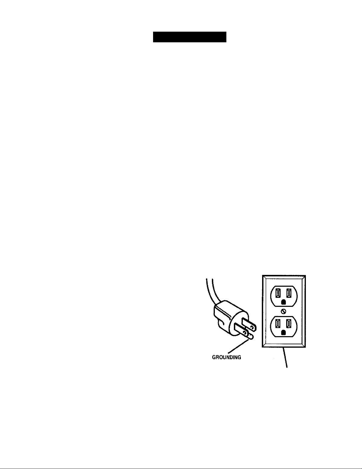
This tool is intended for use on a circuit that has an
outlet like the one shown in Figure 1. It also has a
grounding pin like the one shown.
WARNING: Electrical shock can kilt.
PIN
COVER OF GROUNDED
OUTLET BOX
Figure 1
CRRFTSHRN' TABLE SAW 315.228110
Page 8

GLOSSARY OF TERiVIS FOR WOODWORKING
Anti-Kickback Pawls
Toothed safety devices behind the blade designed to
stop a workpiece from being kicked back at the
operator during a ripping operation.
Arbor
The shaft on which a blade or cutting tool is mounted.
Bevel Cut
A cutting operation made with the blade at any angle
other than 90' to the saw table.
Compound Cut
A cut with both a miter angle and a bevel angle.
Crosscut
A cutting operation made across the grain or the width
of the workpiece.
Dado
A non-through cut that gives a square notch or trough;
requires a special blade.
Featherboard
A device to help guide workpieces during rip cuts.
Freehand (for table saw)
Dangerous practice of making a cut without using rip
or miter fences. See Safety Rules.
Gum
A sticky, sap-based residue from wood products.
Heel
Alignment of the blade.
Kerf
The materia! removed by the blade in a through cut or
the slot produced by the blade in a non-through cut.
Kickback
A hazard that can occur when blade binds or stalls,
throwing workpiece back toward operator.
Leading End
The end of the workpiece pushed into the cutting tool
first.
Miter Cut
A cutting operation made with the miter gage using
any angle other than 0° on the miter gage.
Molding
A non-through cut that gives a varied shape to the
workpiece and requires a special blade.
Push Stick
A device used to feed the workpiece through the saw to
help keep the operator's hands well away from the blade.
Push Block
A device used for non-through cut type operations to
help keep the operator's hands away from the blade.
Rabbet
A notch in the edge of a workpiece.
Resaw
A cutting operation to reduce the thickness of the
workpiece in order to make thinner pieces.
Resin
A sticky, sap-based substance.
Rip Cut
A cut made with the grain of the workpiece.
Saw Blade Path
The area directly in line with the blade — over, under,
behind, or in front of it. Also, the workpiece area
which will be or has been cut by the blade.
Set
The distance that the tip of the saw blade tooth is bent
(or set} outward from the face of the blade.
Throw-Back
Saw throwing back a workpiece; similar to kickback.
Through Sawing
Any cutting operation where the blade extends
completely through the workpiece.
Trailing End
The workpiece end last cut by the blade in a rip cut.
Workpiece
The item on which the cutting operation is being done.
The surfaces of a workpiece are commonly referred to
as faces, ends, and edges.
Worktable
The surface on which the workpiece rests while
performing a cutting operation.
PRODUCT SPECIFICATIONS
Blade Arbor
Blade Diameter
Blade Tilt
Net Weight Without Leg Stand
Net Weight With Leg Stand
CRRFTXMRN* TABLE SAW 315.226110
5/8 in. Rating
10 in.
O’ - 45’
75 lbs.
97 lbs.
Input
No Load Speed
Cutting Capacity with
Cutting Capacity with
120 V, 60 H z-AC only
Miter at O’/Bevel O’:
Miter at OVBevel 45'
15 Amperes
4,800 RPM
3-9/16 in.
2-1/2 in.
Page 9

UNPACKING
Your new table saw has been designed to give you
many years of high quality performance. To insure
this goal< proper care and treatment is important.
Careful treatment begins with removing all parts from
the carton and checking them against the list of loose
parts.
Your table saw is shipped complete in one carton and
includes a teg stand, two table extensions, a rip fence,
a miter fence with adjusting clamp, a blade guard, rails
and hardware.
■ Separate the saw and all parts from the packing
materials and check each against the packing list,
especially the small parts that can be hidden in the
packing material.
Note: Do not discard the packing materials until you
have carefully inspected the saw, identified all
parts, and satisfactorily operated your new saw.
If you are missing a part, check the packaging before
contacting Sears.
If any parts are missing, do not attempt to assemble
your table saw, plug in the power cord, or turn the switch
on until the missing parts are obtained and are installed
correctly. Complete parts lists are located at the end of
this manual. Use these lists to identify the part number
of any missing part. Contact your Sears Service Center
or Retail store and get the missing part(s) before
assembling and trying to use your saw.
WARNING: Never use gasoline, naptha, or
other highly volatile solvents. Do not ever let
brake fluids, gasoline, petroleum-based
products, or penetrating oils contact plastic parts.
Such chemicals can weaken or destroy plastic.
A WARNING: To prevent accidental starting that
could cause possible serious personal injury,
assemble all parts to your saw before connecting
it to power supply. Saw should never be
connected to power supply when you are
assembling parts, making adjustments, installing
or removing blades, or when not in use.
WARNING: If any parts are missing, do not
operate this tool until the missing parts are
replaced. Failure to do so could result in possible
serious personal injury.
ACCESSORIES
The following recommended accessories are currently available at Sears Retail Stores.
Item No. 9-22210 Router Mounting Kit
Item No. 9-22211 Miter Slot Table
Item No. 9-22212 Zero Clearance Throat Plate
Item No. 9-22213 Dado Throat Plate
Item No. 9-22214 Micro-Position Rip-Fence Accessory
Item No. 9-22215 Quick Fold Table
Item No. 9-22216 Wide Table Kit DO NOT USE 7 in. WOBBLE DADOES
Item No. 9-22217 Long Miter/Rip Fence
Item No. 9-22218 Air Floatation Table ^ complete assortment of blades for your saw are
Item No, 9-22219 Wide Table Leg Set available at your nearest Sears Retail Store.
Item No. 9-22220 Miter Clamp Kit
WARNING: The use of attachments or accessories not listed might be hazardous.
^ WARNING: To avoid risk of injury, use
recommended dado and zero clearance throat
plate when employing a dado accessory.
CRHFTIMIIN* TABLE SAW 315.228110
Page 10
LOOSE PARTS LIST
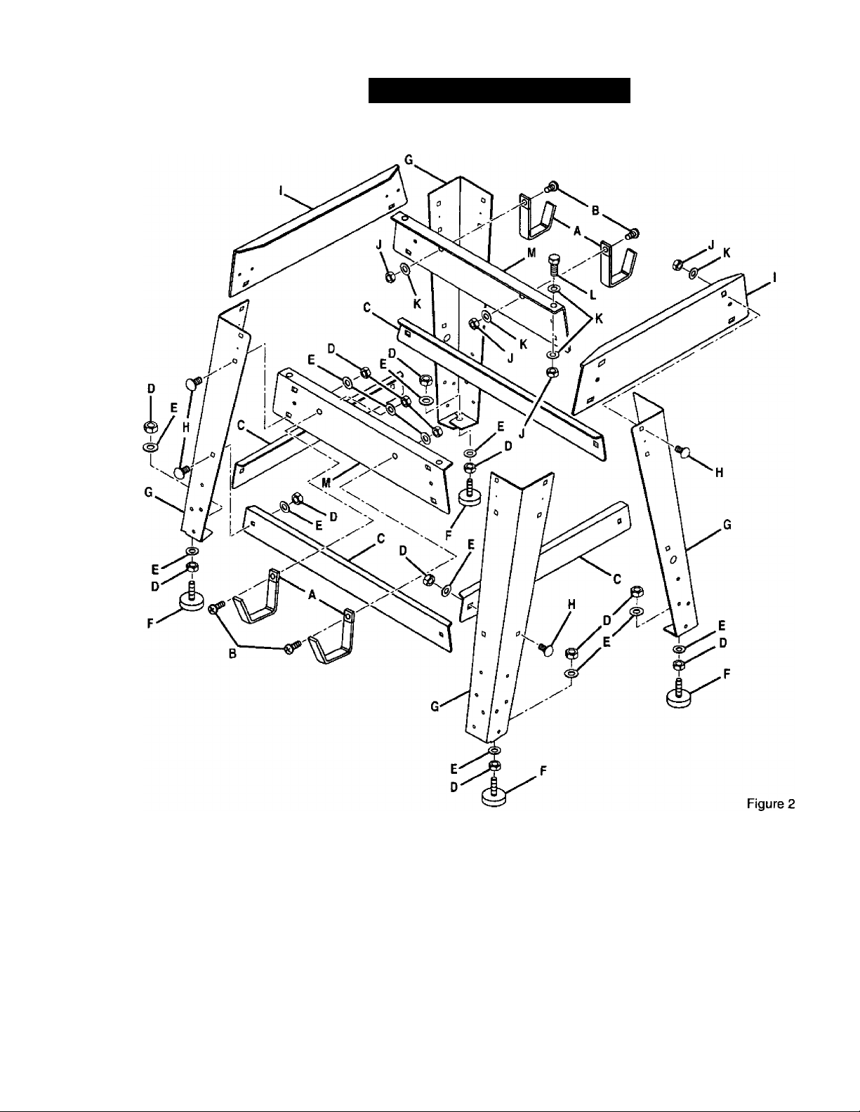
The following items are included with your Table Saw.
A. Storage Bracket.......................................................................4 h. Carriage Bolt (5/16-18 x 3/4 in.)
B. Screw (1/4-20 X 1/2 in. Pan Hd.)...........................................4 I. UpperBrace.........................................................................2
C. Lower Brace.............................................................................4 j. Hex Nut (1/4-20)..................................................................8
D. Hex Nut (5/16-18).................................................................32 K. Washer (1/4 in.).................................................................12
E. Washer (5/16 in.)...................................................................32 L. Bolt (1/4-20 x 3/4 in. Hex Hd.)
F. Leveling Foot...........................................................................4 M. Upper Side Brace...............................................................2
G. Leg.........................................................................................4
CRAFTSHRN' TABLE SAW 31S.228110
10
..................................
............................................
24
4
Page 11
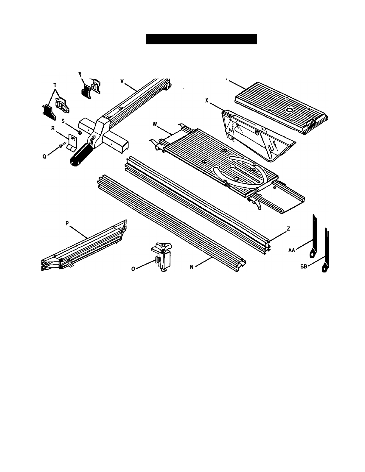
LOOSE PARTS LIST
The following items are included with your Table Saw.
U
N. Front Rail..........................................................................1
O. Miter Fence Holder With Adjusting Clamp
P. Miter Fence With Miter Indicator
Q. Screw................................................................................1
R. Rip Scale Indicator..........................................................1
S. Hex Nut............................................................................1
T. End Plug (Front Rail)
U. End Plug (Rear Rail).......................................................2
V. Rip Fence ........................................................................1
W. Sliding Miter Table
......................................................
...........................................................
.................................
.................
X. Blade Guard With Riving Knife
1
1
2
1
11
And Anti-Kickback Pawls
Y. Accessory Table..............................................................1
Z. Rear Rail
AA. Large wrench
BB. Small wrench......................................................................i
CC. 3/32 in. Hex Key (Not Shown)
DD. 1/8 in. Hex Key (Not Shown)...........................................1
EE. 5/32 in. Hex Key (Not Shown).........................................1
FF. 3/16 in. Hex Key (Not Shown)
.........................................................................
.................................................................
..............................................
........................................
.........................................
CRAFTSMUN' table saw 31S.22B110
Figure 3
1
1
1
1
1
Page 12
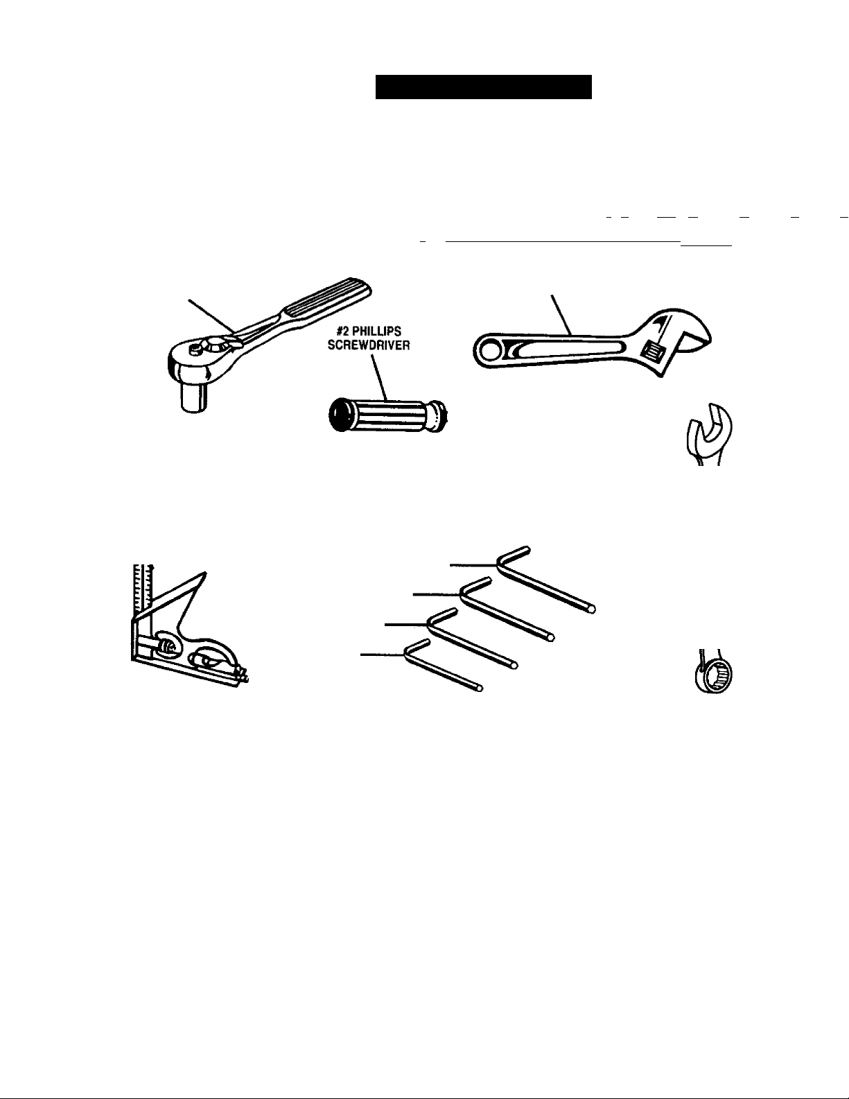
TOOLS NEEDED
The following tools are needed for assembly and alignment. Note: The four hex keys listed below have been
provided with your saw. The remaining tools are typical shop tools and are not included with your saw.
3^ in. NUT DRIVER
SOCKET WRENCH
WITH 7/16 in. SOCKET
m
COMBINATION
— SQUARE
\
FRAMING SQUARE
ttv| 1111 n H > 11| 11 ■ 11 r«'|' 1111 f »1 H 1111 H r 11| n i| 11 n 11111,
11 till I 111 ilililitil.il 1.1.1.i.l.l.l.t.l.i, 1.1 J.t.l.i -
ADJUSTABLE WRENCH
r«'li|iiT/mn|i|iiriii
- -
FLAT BLADE
SCREWDRIVER
€ S i
3/16 in. HEX KEY
3/4 in. —
WRENCH
5/32 in. HEX KEY
1/8 in. HEX KEY
3/32 in. HEX KEY
Figure 4
CRRFTXMRN' TABLE SAW 315.228110
12
Page 13

FEATURES
Your saw is designed to perform as a versatile,
accurate, precision cutting tool that is easy to operate.
It is equipped with the following features for safety,
ease of use, and high-quality performance;
a carbide tipped combination blade
a bevel indicator to set the exact angle of the blade,
with locking lever
an adjustable and reversible sliding miter table
an adjustable miter fence with miter indicator
an adjustable accessory table
an adjustable rip fence with scale indicator
an adjustable riving knife (splitter) and blade guard
with anti-kickback pawls
front and rear guide rails with an easy-to-read scale
on front rail
a dust exhaust (2-1/2 in. hole) that can be adapted
to a standard shop vacuum if desired
blade adjusting handle to set depth of cut
switch with lockable cover plate to help prevent
unauthorized use
• a leg stand
These features provide ease of cutting with all types of
wood.
A WARNING: Before attempting to use your saw,
familiarize yourself with all operating features
and safety requirements.
OPERATING COMPONENTS
The upper portion of the blade projects up through the
table, surrounded by an insert called the throat plate.
To cut wood at a bevel, the blade must be tilted, using
the blade adjustment handle, scale, and bevel indica
tor found on the front of the cabinet. Inside the
cabinet, adjustable positive stops control the degree
of movement.
The sliding miter table assembly is used for all cross
cutting operations. The miter fence is easily adjusted
to cut wood at an angle by loosening the adjusting
clamp, setting the fence to the miter scale, and
retightening the clamp. The sliding miter table, which
rests on a base mounted on the rails, can be reposi
tioned along the rails for wide work. It can be reversed
for ripping so the projecting base is in the back.
Your saw includes a rip fence and an accessory table.
The accessory table can be moved from the right side
of the saw to the left side as needed. The rip fence is
used to position work that wili be cut lengthwise. A
scale on the front rail shows the distance between the
rip fence and the blade.
A CAUTION: The saw blade "coasts” after the
saw is turned off.
SPEED AND WIRING
The no-load speed of your table saw is approximately
4,800 rpm. The speed will not remain constant but will
be less under a load. The wiring in a shop is as
important as the motor's horsepower rating. A line
intended for lights only
will not properly carry a
power tool motor. Wire that is heavy enough for a
short distance will be too light for a greater distance. A
line that can support one power tool may not be able
to support two or three tools.
A_ WARNING: To prevent possible electrical
hazards, have a qualified electrician check the
line if you are not certain that it is properly wired.
WARNING: Observe all normal safety
precautions related to avoiding electrical shock.
SAFETY DEVICES
Safety devices on your saw include the blade guard,
the anti-kickback pawls, and the riving knife (also
known as a splitter or spreader). The blade guard is a
clear strong plastic shield designed to prevent acci
dental contact with the blade. It also deflects any
flying debris from within.
WARNING: Although many of the illustrations in
this manual are shown with the blade guard
removed for clarity, do not operate the saw
without the blade guard unless specifically
instructed to do so.
The riving knife is a metal device directly behind and
above the blade. It is used to help keep the cut wood
from binding together and causing possible kickback. It
is very important to use the riving knife tor all throughsawing operations. The anti-kickback pawls are
toothed plates mounted on the riving knife. Their teeth
point away from the work in case the work should be
pulled back, toward the operator. Then the teeth dig
into the wood to help prevent or reduce the possibility
of kickback.
Your saw features a receptacle on the right side of the
cabinet that permits use of accessories. Use only
accessories that are listed for use with this tool. When
using a listed accessory, unplug the saw motor cord
and use the receptacle and the saws main power
switch to operate the accessory.
13
CRAFTSMAN' TABLE SAW 315.228110
Page 14
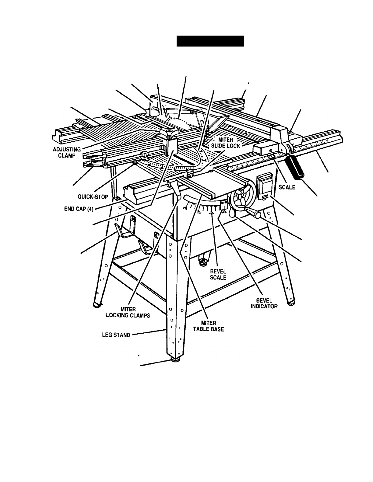
KNOW YOUR TABLE SAW
FEATURES
BLADE GUARD
ANTI-KICKBACK
^ pawls
SLIDING
MITER TABLE THROAT PLATE
MITER
FENCE
MITER
FENCE HOLDER
STORAGE
8RACKET(S)
RIVING KNIFE
SAW BLADE
MITER SCALE
REAR RAIL
RIP FENCE
ACCESSORY TABLE
FRONT RAIL
LOCKING HANDLE
SWITCH WITH
LOCKABLE COVER
BLADE
ADJUSTING HANDLE
BEVEL
LOCKING LEVER
LEVELING FOOT
CRHFTSMRK' TABLE SAW 315.228110
Figure 5
14
Page 15
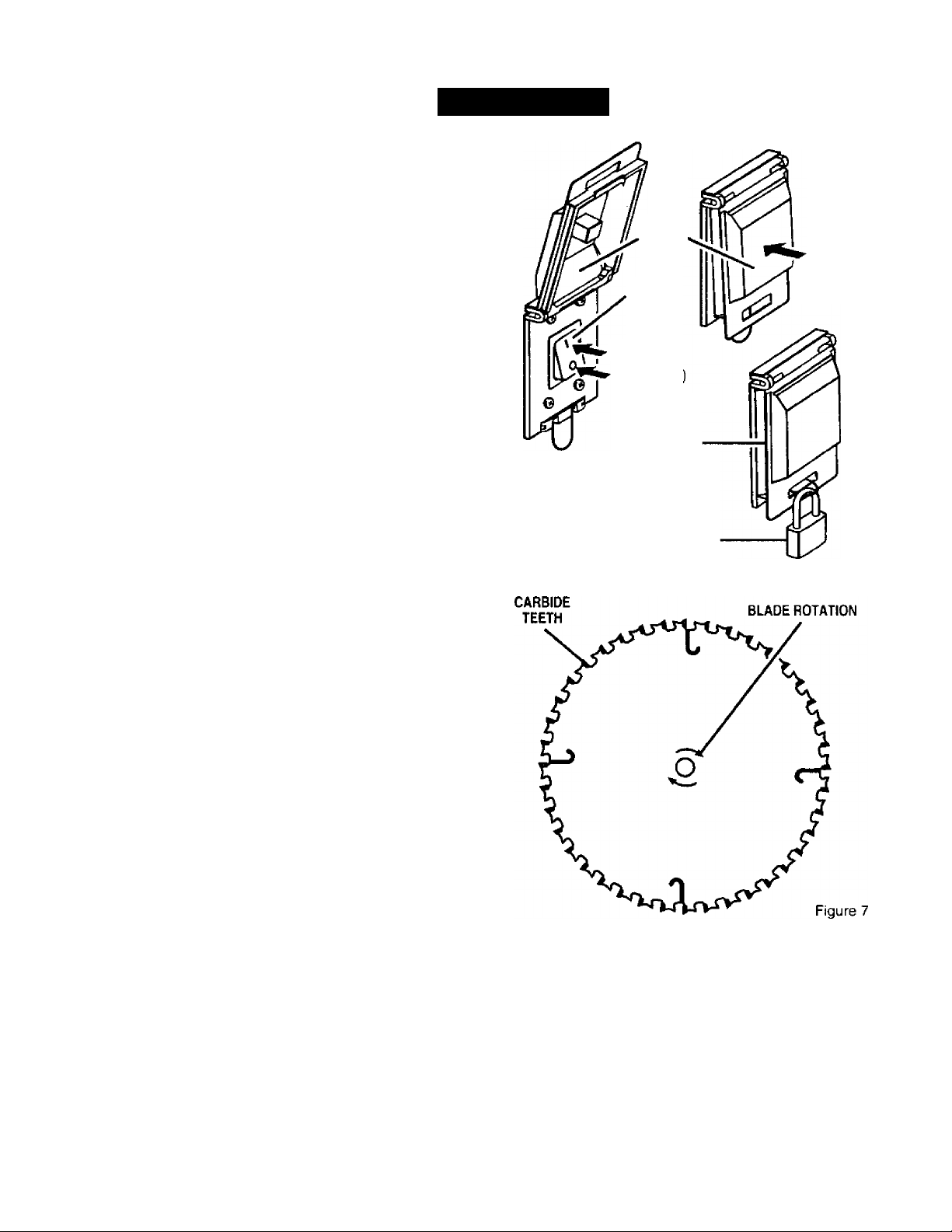
POWER SWITCH
See Figure 6.
Your saw is equipped with a switch that utilizes a
lockable switch cover to prevent unauthorized use.
With the saw turned Off, a padlock can be used to
secure the switch cover over the switch. This prevents
anyone from starting your saw without removing the
padlock, lifting the switch cover, and pressing the
switch button.
TO TURN YOUR SAW ON:
■ Lift switch cover.
■ Press switch button.
■ Lower switch cover.
TO TURN YOUR SAW OFF:
■ (A) Press or push outside of switch cover, or
(B) Lift switch cover and press switch button.
TO LOCK YOUR SAW SWITCH:
■ Raise switch cover.
■ Align metal loop through slot in switch cover while
lowering switch cover.
■ Place shackle of padlock (not provided) through
the metal loop and close padlock.
FEATURES
SWITCH
COVER
SWITCH
BUTTON
TO START
TO STOP(B
TO LOCK IN
OFF POSITION
PADLOCK
(NOT PROVIDED)
TO
'STOP (A)
Figure 6
WARNING: Always make sure your workpiece
is not in contact with the blade before operating
the switch to start the tool. Failure to heed this
warning may cause the workpiece to be kicked
back toward the operator and result in serious
personal injury.
WARNING: To reduce the risk of accidental
starting, Always make sure the switch is in the
Off position before plugging tool into the power
source.
BLADES
See Figure 7.
For maximum performance, it is recommended that
you use the Craftsman 40 tooth, 10 inch carbide
tipped combination blade provided with your saw. It is
a high-quality carbide tipped combination blade
suitable for ripping and crosscut operations. Other
recommended blades are listed in the accessory
section of this manual.
Check with your nearest Sears Retail Store for other
high quality blades as they become available.
CAUTION: Be sure to use only blades that are
rated tor at least 5,500 rpm and recommended
for use on this saw. Check with your nearest
Sears retail store.
15
CRflFTSHRN' TABLE SAW 315.226110
Page 16
ASSEMBLY
Assembly is best done in the ares where the saw will be used. When you remove the table saw base, loose
parts, and hardware from the packing materials, check all items with the loose parts list and drawing. If you are
unsure about the description of any part, refer to the drawing. If any parts are missing, delay assembling until
you have obtained the missing part(s}.
A. ASSEMBLY OF LEG STAND, STORAGE
BRACKETS, AND MOUNTING TO SAW
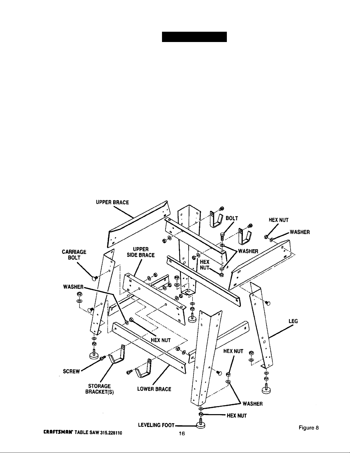
ASSEMBLING LEG STAND
See Figures 8 and 9.
■ Take the following hardware from the leg stand
hardware bag:
24 carriage bolts (5/16-18 x 3/4 in.)
4 leveling feet
32 flat washers (5/16 in.)
32 hex nuts (5/16-18)
Note: Remaining hardware from this bag is used for
mounting leg stand on the table saw base and
mounting storage brackets to upper brace.
■ Take 4 legs and 8 braces from loose parts.
■ Place an upper side brace inside two of the tegs.
with the legs wide end up. (Upper side braces have
two large holes in each end.) Make sure the two
posts on the leg align with the small holes on the
brace.
Align the two large holes on the brace and the
legs. Insert the carriage bolts. Add fiat washers
and hex nuts and hand tighten. Repeat for the
other upper brace. These are the front and back
sets.
For the side sets, install a upper brace on two legs.
Add hardware and finger tighten. Repeat for the
other upper brace.
Use the same steps to install the lower braces.
Tighten all hex nuts with a 12 mm wrench.
Place a hex nut and flat washer on each leveling
foot. Install the leveling feet from the bottom of
Page 17
ASSEMBLY
each leg with the bolts pointing up. Cap with the
remaining flat washers and hex nuts but do not
tighten,
■ Move the leg set to desired location. Adjust the
leveling feet with a 12 mm wrench, then tighten the
top hex nut.
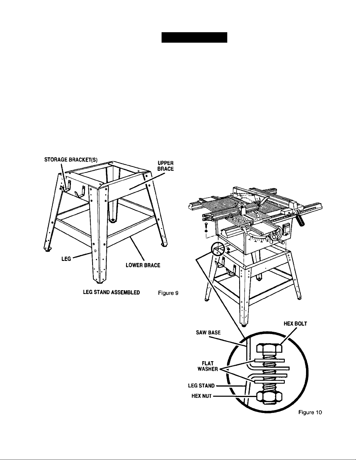
ASSEMBLING STORAGE BRACKETS
See Figure 8.
■ Take storage brackets from loose parts.
■ Take the following hardware from the leg stand
hardware bag:
4 screws (1/4-20 x 1/2 in. Pan Hd.)
4 hex nuts (1/4-20}
4 washers (1/4 in.)
■ Place the saw table upside down on a smooth
surface, such as cardboard, on the floor.
WARNING: Do not lift the saw without help.
The saw base weighs approximately 75 lbs. Hold
it close to your body. Keep your knees bent and
lift with your legs, not your back. Ignoring these
precautions can result in back injury.
■ Place the leg stand on the table saw base. Align
the holes in the table with the holes in the end
braces.
■ Place a flat washer on a bolt and insert through
hole. Add a flat washer and a hex nut. Hand
tighten. See Figure 10.
■ Repeat for three remaining holes. Tighten all
hardware with a 12 mm wrench. You may find it
helpful to use one wrench to hold the head of the
bolt and one to tighten the hex nut.
■ Secure storage brackets to upper braces of leg
stand as shown in figures 8 and 9.
Note: If you mount the saw base on a bench instead
of the legs, go to the Assembly of Rails, Tables,
Fences procedure. The bench surface must
have an opening for sawdust to fall through, as
large as the opening in the bottom of the saw
base. A height of 36 in. from the top of the saw
table to the floor is recommended.
MOUNTING THE LEG STAND ON THE TABLE
SAW BASE
See Figure 10.
■ Take the following from a small hardware bag;
4 hex bolts (1/4-20 X 3/4 in.)
4 hex nuts (1/4-20)
8 flat washers (1/4-20 in.)
Note: This hardware was in the bag with hardware for
assembling the leg stand and leveling feet.
17
CIlflFTlHIlN* TABLE SAW 315.228110
Page 18

ASSEMBLY
WARNING: Do not connect to power supply
until assembly is complete. Failure to comply
could result in accidental starting and possible
serious injury.
B. ASSEMBLY OF RAILS, TABLES, AND
FENCES
TO INSTALL FRONT AND BACK RAILS
■ Position end caps on both rails and secure in place
by tapping with a block of wood or a rubber mallet,
■ Loosen the front rail clamps one-half (1/2) turn
from the tightened position. Loosen the square rail
holder nut one-fourth (1/4) turn to allow the front
rail to slide over it. See Figures 11 and 12.
■ Mount the front rail with the scale facing the
outside toward the operator.
■ Check to make sure the rail clamps will securely
clamp the rail before sliding the entire assembly
into position. If not, repeat steps 2 and 3 above.
■ Slide the rail into position over both clamps and
secure.
■ Mount the rear rail, following the same clamping
procedure as shown for the front rail. Orient the
rear rail as shown in figure 12.
TO INSTALL MITER TABLE AND FENCE
■ Install the sliding miter table assembly over the
front and rear rails. See Figure 13. Check that it
slides easily on the rails. Push both front miter
locking clamps down evenly on each side to
secure. Repeat for both rear miter locking clamps.
Note: Do not force miter locking clamps fully
down. Tighten only to flat “seated" position.
■ To install the miter fence holder to the miter fence,
loosen the attachment bolt by turning the adjusting
clamp (the knob on top) counterclockwise. Make
sure the adjusting clamp is loose enough so the
bolt has enough clearance to slide in the table slot.
Slide the tabs into the grooves in the miter fence.
See Figure 14.
■ Mount the miter fence to the miter table by install
ing the locator pin (below the miter fence) into hole
“A” or “B". (Hole “A" is closest to the blade). At the
same time, place the attachment bolt in the slot.
Secure the adjusting clamp, but do not tighten.
Note: Hole “A” should be used for short pieces of
wood and hole “B" should be used for long pieces
of wood.
■ Adjust the miter indicator to the scale.
■ Retighten the adjusting clamp.
FRONT
RAIL CLAMP
LOCKING
LEVER
FRONT RAIL
BLADE
ADJUSTING HANDLE
END CAP
REAR RAIL
Figure 11
CRAFTSMAN' TABLE SAW 315.228110
Figure 13
18
Page 19

ASSEMBLY
TO INSTALL ACCESSORY TABLE AND RIP
FENCE
^ Place the accessory table on the front and rear rails,
fitting the lip into the rear rail. Position the slot on the
underside of the accessory table onto the front rail
and tighten the lever securely. See Figure 15.
■ Screw the locking handle into the rip fence mounting
hole. See Figure 16.
■ Remove the scale indicator assembly from the plas
tic bag and install on either side of the fence. The
pan head screw (#8-32 x 1/2 in.) goes on the outside
of the front block. The scale indicator and hex nut
(#8-32) go immediately behind the front lip of the front
block.
■ To install the rip fence, place the rear tip on the rear
rail and pull slightly toward the front of the unit. Lower
front end onto the guide surfaces on top of the front
rail. Check for a smooth gliding action. Swing the
locking handle down to automatically align and se
cure the fence. When securely locked, the locking
handle should point downward.
WARNING: Do not connect to power supply
until assembly is complete. Failure to comply
could result in accidental starting and possible
serious injury.
MITER FENCE
MITER
INDICATOR
HOLE“B
ADJUSTING CLAMP
MITER FENCE
HOLDER
TABLE SLOT
ATTACHMENT
BOLT
Figure 14
ACCESSORY
TABLE
REAR RAIL
C. BLADE CHECK AND BLADE GUARD
ASSEMBLY
TO CHECK SAW BLADE INSTALLATION
■ To check the saw blade, first remove the three
screws holding the throat plate in place. Remove
the throat plate. See Figure 17.
M Make sure the bevel locking lever is securely pushed
to the left. Raise the blade arbor to its full height by
turning the blade adjusting handle clockwise.
■ Using the smaller hex wrench, insert the flat open
end into the flats on the arbor shaft as shown in
figure 18. Insert the larger hex wrench over the hex
nut, and, holding both wrenches firmly, pull the
larger wrench forward to the front of the machine to
loosen and push to tighten. Make sure the blade
nut is securely tightened. Do not overtighten.
Note: Arbor shaft has left hand threads.
■ Check all clearances for free blade rotation.
■ See To Set the Scale to the Blade in the
Operation Section. In cutting operations, the scale
will be set to the side of the blade where the cut
will be measured and made.
TO
LOCK LEVER
FIT LIP OF TABLE
INTO REAR RAIL
Figure 15
RIP FENCE
19
tRRFTSMIlN’ TABLE SAW 315.228110
Page 20

ASSEMBLY
TO INSTALL BLADE GUARD
■ To install the blade guard, first remove the three
screws holding the throat plate in place. Remove
the throat plate. See Figure 17.
■ Make sure that the locking lever is securely pushed
to the left. Raise the blade arbor to its full height by
turning the blade adjusting handle clockwise.
■ Move the locking lever to the right for Angle mode.
Slowly turn the blade adjustment handle to put the
blade at 30 degrees. The handle will "pop out"
slightly as it engages the clutch.
■ Holding the blade adjusting handle with one hand,
use the other hand to push the locking lever firmly
to the left to lock the angle.
■ Using the small hex wrench, install the blade guard
by loosening the two attachment hex nuts enough
to slide the riving knife down between the shims.
Do not remove the hex nuts. See Figure 19.
Partially retighten the two attachment nuts. Check
the blade and riving knife alignment.
■ Correctly align the blade and riving knife as shown,
repeating step 5 as needed. Tighten attachment
nuts securely. If riving knife is not positioned
correctly, with blade up, it could contact saw table
when blade is lowered and restrict blade elevation.
■ Blade alignment with the riving knife can be
adjusted for different blade widths. Refer to
Settings and Adjustments in the Operations
Section.
■ Check the blade guard assembly for clearances
and free movement. Reinstall the throat plate into
the opening, lower the blade and secure the three
attachment screws. Tighten the screws securely.
SMALL HEX
WRENCH
LARGE
HEX WRENCH
NOTE; PLACE BLADE BETWEEN
INNER AND OUTER BLADE WASHER
LARGE
HEX WRENCH
OUTER
BLADE WASHER
ARBOR NUT TIGHTEN
THROAT PLATE
Figure 17
ARBOR
INNER
BLADE WASHER
Figure 18
CRRFTSHDN* TABLE SAW 315.228110
MOUNTING
PLATE
Figure 19
20
Page 21

A. GENERAL INFORMATION GROUNDING
Your saw's three-prong plug must be plugged into a
matching outlet that is properly installed and grounded
in accordance with all local codes and ordinances.
Improper connection of the equipment can result in
electric shock. Check with an electrician or service
personnel If you are unsure about proper grounding.
Do not modify the plug; if it will not fit the outlet, have
the correct outlet installed by a qualified electrician.
To temporarily use the saw with a two-prong outlet,
use an adapter, provided the outlet is properly
grounded. Make sure the extending green wire is
connected to the outlet-plate retaining screw. The
temporary adapter should be used only until a prop
erly grounded outlet can be installed by a qualified
electrician, and only if ordinances permit such use.
WARNING: If an extension cord is used, make
sure it has a three-prong plug and is large
enough to prevent excessive voltage loss.
OPERATION
PIN
©
(S>
©
I
COVER OF GROUNDED
OUTLET BOX
Figure 20
Д WARNING: The saw's motor cord must only be
plugged into the receptacle provided on the saw
which is controlled by the saw's master switch.
Never plug the motor cord directly into an
extension cord as this will prevent the ability to
switch the saw off.
TYPES OF CUTS
There are six basic types of cuts; the straight cross
cut, the miter cut, the rip cut, the bevel cross cut, the
bevel rip cut, and the bevel miter cut {compound miter
cut). All other cuts are of these basic six. Operating
procedures for making each kind of cut are given later
in this section.
WARNING: Always make sure the blade guard
and anti-kickback pawls are in place and working
properly when making these cuts to avoid
possible injury.
Cross cuts are straight, 90 degree cuts made across
the grain of the workpiece. The wood is fed into the
cut at a 90 degree angle to the blade and the blade is
vertical. See Figure 22.
Miter cuts are made with the wood at any angle other
than 90 degrees. See Figure 23. (The wood is angled
to the blade.) Miter cuts may tend to “creep" away
from the miter fence during cutting. This can be
controlled by holding the workpiece securely against
the miter fence. The miter clamp kit has been de
signed and tested for this purpose.
21
CRRFTSHRN* TABLE SAW 315.228110
Page 22

Rip cuts are made with the grain of the wood. See
Figure 24. To help control kickback while making a rip
cut, keep the anti-kickback pawls properly maintained
and adjusted, make sure one side of the wood rides
firmly against the fence, and always use a push stick
with small or narrow pieces of wood.
Note: Push sticks should also be used to finish a cut
when ripping long narrow pieces of wood, to prevent
your hands from getting close to the blade. See
Figure 34.
Bevel cross cuts are made with an angled blade,
cutting wood across the grain.
Bevel rip cuts are made with an angled blade, cutting
wood with the grain. See Figure 25.
Note: The fence must always be on the left side of the
blade when making bevel cuts. See Figure 45.
Compound or bevel miter cuts are made with an
angled blade on wood that is angled to the blade. Be
thoroughly familiar with making straight cross cuts,
bevel cross cuts, and miter cuts before trying a
compound miter cut. See Figure 26.
CUTTING TIPS
Dado and rabbet cuts are non-through cuts which can
be either rip cuts or cross cuts. Carefully read and
understand all sections of this owner’s manual before
attempting any operation.
OPERATION
WARNING: All blades and dado sets must be
rated for at least 5,500 RPM to prevent possible
injury.
■ The kerf (the cut made by the blade in the wood)
will be wider than the blade to avoid overheating or
binding. Make allowance for the kerf when
measuring wood.
■ Make sure the kerf is made on the waste side of
the measuring line.
■ Cut the wood with the finish side up.
■ Knock out any loose knots with a hammer before
making the cut.
■ Always provide proper support for the wood as it
comes out of the saw.
■ See the Accessories Section in this manual for a
list of recommended blades.
CltnFTSMIlN' TABLE SAW 31S.22S110
22
Page 23

OPERATION
В. SETTINGS AND ADJUSTMENTS
THROAT PLATE
TO REMOVE THE BLADE
Use the two wrenches supplied with the saw for this
procedure.
Д WARNING: Unplug your saw and make sure
the blade guard assembly is installed and
working properly to avoid serious personal injury.
■ Raise the blade guard. See figure 27, overview of
saw.
Ш
Remove the three screws from the throat plate and
lift the throat plate out of the slot.
■ Push the bevel locking lever to the left for elevation
mode.
■ Raise the blade to its full height by turning the
blade adjusting handle clockwise.
■ Place the open end of the small hex wrench into
the slot beside the blade. The wrench will fit over
two fiats on the arbor (blade shaft}. See
Ш
Fit the large hex wrench onto the arbor nut. Turn
clockwise and remove the nut. taking care not to
drag your knuckles across the blade.
Figure 28.
Note: The arbor nut has left-hand threads.
■ Remove the outer blade washer from the arbor and
then remove the blade. Make sure that inner blade
washer and both spacers are tight against arbor
shoulder.
■ Replace with a new blade. Make sure the blade
teeth are pointing forward, toward incoming work.
■ Put the outer blade washer and arbor nut back on,
aligning with the flats on the arbor. Tighten the nut
with a counterclockwise turn.
Note: Use care not to cross thread arbor nut. Do
not overtighten.
■ Rotate the blade by hand to make sure it is turning
freely.
■ Check the riving knife and adjust if needed (See
next procedure).
■ Insert the throat plate, lower the blade, then secure
the throat plate with the three throat plate screws.
Tighten the screws firmly.
■ Push bevel locking lever to the left to allow blade
elevation and lowering.
TO ANGLE BLADE,
PUSH BEVEL LOCKING
BLADE GUARD
TO LOWER BLADE, PUSH BEVEL
LOCKING LEVER LIFT AND
LOCKING LEVER LEFT AND TO LOCK BLADE ANGLE,
ROTATE BLADE ADJUSTING PUSH BEVEL LOCKING
HANDLE CLOCKWISE LEVER LEFT f:¡g^Jre 29
23
CRRFTSHRN' TABLE SAW 315.228110
Page 24

TO CHECK, REPLACE OR ADJUST THE RIVING
KNIFE AND BLADE GUARD ASSEMBLY
The riving knife is mounted between several shims
that can be relocated as needed to center the knife
behind the blade. It is held in place by two bolts and
hex nuts at its base. The bolts are set in slots that
permit front-to-back adjustment.
WARNING: Unplug the saw before working on
it. If the saw is not unplugged, accidental start-up
may occur, resulting in possible serious injury.
OPERATION
REMOVE THE THROAT PLATE.
■ With blade guard up, make sure the riving knife is
placed at feast 1/8 inch from the outer points of the
blade. See Figure 31. Then make sure it is
centered within the width of the blade. See Figure
32. If either placement is wrong, adjust with the
following steps.
■ Raise the saw blade by pushing the bevel locking
lever to the left and rotating the blade adjustment
handle clockwise.
■ Put the saw in Angie mode by moving the bevei
locking lever to the right. Slowly turn the blade
adjusting handle until the bevel indicator is at a 30
degree angle. Lock the angle by holding the blade
adjusting handle with one hand and returning the
bevel locking lever to the left with the other.
■ With the box end of the small hex wrench, loosen
the two nuts at the base of the riving knife. Do not
remove nuts. Remove the riving knife/guard
assembly. .
■ Rearrange the riving knife between the shims to
achieve the correct centering.
WARNING: Properly align riving knife.
Improperly aligned riving knife may cause blade
to bind which will increase risk of kickback.
RIVING KNIFE
BLADE
RIVING KNIFE
THROAT PLATE
Figure 30
BLADE
Figure 31
■ Adjust the bolts front-to-back as needed to place
the riving knife approximately 1/8 inch from the
blade’s outer points. Tighten with the smalt hex
wrench to secure the riving knife and blade guard
assembly.
■ Bring the blade back to the desired angle and
height. Insert the throat plate, tower the blade, and
secure the throat piate with the three throat plate
screws. Tighten the screws firmly.
CRRFTSMRN* TABLE SAW 31S.228110
LOOSEN NUTS,
RIVING KNtFEAND
GUARO ASSEMBLY
TO CENTER RIVING KNIFE,
REARRANGE SHIMS Figure 32
24
Page 25

OPERATION
TO REDUCE RISK OF KICKBACK
Kickback can occur when the blade stalls or binds,
kicking the workpiece back toward you with great
force and speed. If your hands are near the saw
blade, they may be jerked loose and thrown into the
blade. Obviously, kickback can cause serious injury,
and it is well worth using precautions to avoid the
risks.
Kickback can be caused by any action that pinches
the biade in the wood, such as the foilowing:
• making a cut with incorrect blade depth
• sawing into knots or nails in the workpiece
• twisting the wood while making a cut
• making a cut with a dull, gummed-up, or im
properly set blade
• failing to support work
• forcing a cut
• cutting warped or wet lumber
• misusing the saw
• not following correct operating procedures
• failing to use the anti-kickback pawls
• using the wrong blade for the type of cut
TO AVOID KICKBACK
Use these guidelines to avoid kickback:
■ Always use the correct blade depth setting. The
top point of the blade teeth should dear the workpiece,
1/8 inch to 1/4 inch.
■ Inspect the work for knots or nails before beginning
a cut. Knock out any loose knots with a hammer.
Never saw into a loose knot or nail.
■ Make straight cuts. Always use the rip fence when
rip cutting. This helps prevent twisting the wood in
the cut.
■ Always use clean, sharp, and properly-set blades.
Never make cuts with dull blades.
■ To avoid pinching the blade, support the work
properly before beginning a cut.
■ When making a cut, use steady, even pressure.
Never force cuts.
■ Do not cut wet or warped lumber.
■ Always hold your workpiece firmly with both hands
or use push blocks, push sticks, and featherboards
to keep your body in a balanced position to be able
to resist kickback should it occur. Use
featherboards and push sticks to control non
through cuts on small workpieces.
ANTI-KICKBACK
PAWLS IN PLACE
NO KNOTS, NAILS OR WARPS IN WOOD,
WOOD FED AND SUPPORTED CORRECTLY
CORRECT
BLADE DEPTH
Figure 33
Figure 34
25
CIIAFTSMIIN' TABLE SAW 315.228110
Page 26

OPERATION
WARNING: Never stand directly in line with the
blade or allow hands to come closer than 3
inches to the blade. Do not reach over or across
the blade. Failure to comply can result in serious
personal injury.
■ Use the right type of blade for the cut being made.
TO MAKE A PUSH STICK
A push stick is a device used to safely push a
workpiece through the blade instead of using your
hands. Push sticks in various sizes and shapes can
be made from scrap wood. The stick must always be
narrower than the workpiece. If it is too wide, it may
jam on the rip fence or blade. When ripping narrow
stock, always use a push stick so your hand does not
come close to the saw blade.
Note: Push blocks and featherboards should always
be used when making non-through cuts.
A simple push stick design is shown in figure 34.
Remember that the stick must always be narrower
than the workpiece to avoid risk of injury.
FEATHERBOARD
A featherboard is a device used to help control the
workpiece by guiding it securely against the table or
fence. Featherboards are especially useful when
ripping small workpieces and for completing non
through cuts. Featherboards are made from a solid
piece of straight grain wood, free from splits or knots,
HOW TO MAKE A FEATHERBOARD
The featherboard is an excellent project for your
saw. Select a solid piece of lumber approximately 3/4 in.
thick, 3-5/8 in. wide and 18 inches long. Mark the
center of the width on one end of the stock. Miter
one-half of the width to 30° and miter the other half
of the same end to 45°. See page 29 for information
on miter cuts. Mark the board from the point at 6 in.,
8 in., 10 in. and 12 in. Drill a 3/8 in. hole at the 8 in.,
10 in., and 12 in. marks as indicated in figure 35.
Prepare the saw for ripping as discussed on page
29. Set the rip fence to allow approximately a 1/4 in.
"finger" to be cut in the stock. Feed the stock only to
the mark previously made at 6 inches. Turn the saw
Off and allow the blade to completely stop rotating
before removing the stock. Reset the rip fence and
cut spaced rips into the workpiece to allow
approximately 1/4 in, fingers and 1/8 in. spaces
between the fingers. See Figure 35.
HOW TO MOUNT A FEATHERBOARD
Remove the adjusting clamp knob, bolt and washer
from the Miter Fence Holder. Place the bolt through
one of the holes in the featherboard. Positioning the
featherboard will depend on the placement of the bolt
and the position of the sliding miter table on the rails.
Place the washer on the bolt and attach the adjusting
clamp knob, loosely. Position the featherboard with
the hex head of the bolt in the miter table slot but do
not tighten. Completely lower the saw blade. Position
the rip fence to the desired adjustment for the cut to
be performed and lock. Place the workpiece against
the fence and over the saw blade area. Adjust the
featherboard to apply resistance to the workpiece just
forward of the blade. Securely tighten the adjusting
clamp knob to secure the featherboard in place.
Attach a C-clamp to further secure the featherboard to
the edge of the Sliding Miter Table.
WARNING: Do not locate the featherboard to
the rear of the workpiece. Kickback can result
from the featherboard pinching the workpiece
and binding the blade in the saw kerf if
positioned improperly. Failure to heed this
warning can result in serious personal injury.
CRHFTSHflN* TABLE SAW 315.228110
3/8 INCH DIAMETER
26
Page 27

TO ADJUST THE BLADE DEPTH
The blade depth should be set so that the outer points
of the blade are higher than the workpiece by approxi
mately 1/8 in. to 1/4 in. but the lowest points (gullets)
are below the top surface. See
Figure 36.
WARNING: Unplug the saw and make sure the
blade guard assembly is installed and working
properly to avoid serious personal injury.
■ Push the bevel locking lever to the left for elevation
mode.
■ Raise the blade by turning the blade adjusting
handle clockwise or lower it by turning the handle
counterclockwise.
TO ADJUST THE BLADE ANGLE
See Figure 37.
WARNING: Unplug the saw and make sure the
blade guard assembly is installed and working
properly to avoid serious personal injury.
OPERATION
■ Push the bevel locking lever to the right for angle
mode.
■ Angle the blade by turning the blade adjusting
handle until the bevel indicator shows the correct
angle.
■ Return the bevel locking lever securely to the left to
lock the angle, white holding the blade adjusting
handle in place.
TO SET THE SCALE TO THE BLADE
The scale is usable from 0*24 in, to the right side of
the blade and 0-21 in. on the left side of the blade.
The operator can select any desired dimension within
those ranges. Use the following steps to set the scale
to the blade and scale indicator. Begin with the blade
at a zero angle (straight up). See Figure 38.
■ Loosen the rip fence by raising the locking handle.
■ Using a framing square, set the rip fence 2 in. from
the blade tip edge.
■ Loosen both front and rear rails by lifting the front
and rear rail clamps. See Figure 37.
■ Adjust the front rail until the 2 in, mark is placed at
the scale indicator. Align the rear rail to the front
rail.
■ Tighten the rails and check the dimension and the
rip fence in both directions.
Figure 37
27
CRRFTSMRN' TABLE SAW 315.228110
Page 28

OPERATION
TO LOCK MITER TABLE
See Figure 39.
The miter table slides to let the operator slide the
workpiece across the saw. A miter slide lock is
mounted on the front of the miter table to lock it in
place. The miter slide lock is placed in a slot on the
base to align the miter table with the front edge of the
saw table. The sliding miter table should be locked for
any cut in which the operator prefers a fixed table.
■ To lock the miter table with the base projecting to
the front, place miter slide lock in the back slot on
the base.
9 To lock the miter table with the base projecting to
the back, place miter slide lock in the front slot on
the base.
C. MAKING CUTS
The blade provided with your saw is a high-quality
carbide tipped combination blade suitable for ripping
and crosscut operations. Check with your Sears Retail
Store for other recommended blades.
WARNING: All blades must be rated for at least
5,500 RPM to prevent possible injury.
MITER
SLIDE LOCK
MITER FENCE
QUICK STOP
SLOT FOR LOCKING
MITER TABLE
Figure 39
ADJUSTING CLAMP
TO MAKE A STRAIGHT CROSS CUT
See Figure 40.
It is recommended you make test cuts on scrap wood.
iV WARNING: Never use rip fence as cutoff gauge
when crosscutting.
WARNING: Make sure the blade guard
assembly is installed and working properly to
avoid serious personal injury.
■ Remove the rip fence by lifting the locking handle.
■ Set the blade to the correct depth for the
workpiece.
■ Set the miter fence to 90 degrees with the quick
stop or the miter scale.
■ Make sure the miter fence won't touch the blade
while feeding the wood. Make a trial pass of the
miter table. The miter fence should not contact the
blade. Loosen the adjusting clamp to move the
fence if needed.
■ Place a support (the same height as saw table)
behind the saw for the cut work. See Quick Fold
Table in Accessories on page 9.
■ Make sure the wood is clear of the blade before
turning on the saw.
■ To turn saw On, lift switch cover and'press switch
button. Then tower switch cover.
MITER
TABLE BASE
SWITCH
COVER
SWITCH
BUnON
TO START
TO STOP(B)
TO LOCK IN
OFF POSITION
PADLOCK
(NOT PROVIDED)
Figure 40
TO
STOP(A)
Figure 41
CRRFTSMRN' TABLE SAW 315.228110
28
Page 29

OPERATION
■ To turn saw Off, (A) press or push outside of
switch cover, or (B) lift switch cover and press
switch button. See Figure 41.
Note: To prevent unauthorized use, lock your saw
in the Off position with a padlock as shown in
figure 41,
■ Let the blade build up to full speed before moving
the miter table to feed the workpiece into the blade.
■ Hold the work firmly against the miter fence with
both hands and push the miter table to feed the
work into the blade.
TO MAKE A MITER CUT
See Figure 42.
It is recommended you make test cuts on scrap wood.
^ WARNING: Make sure the blade guard
assembly is installed and working property to
avoid serious personal injury.
■ Remove the rip fence by lifting the locking handle.
■ Loosen the adjusting clamp to set the desired
angle of the miter fence. Place the miter indicator
on the miter fence to the desired angle on the miter
table. Retighten the clamp.
■ Place a support (the same height as saw table)
behind the saw for the cut work. See Quick Fold
Table in Accessories on page 9.
■ Make sure the miter fence will not contact the
blade while feeding the wood. Make a trial pass of
the miter table. The miter fence should not contact
the blade. Loosen the adjusting clamp to move it
away from the blade if needed.
■ Make sure the wood is clear of the blade before
turning on the saw.
■ Let the blade build up to full speed before moving
the miter table to feed the workpiece into the blade.
■ Hold the work firmly against the miter fence with
both hands, keeping well clear of the blade, and
push the miter table to feed the work into the
blade.
TO MAKE A STRAIGHT RIP CUT
See Figure 43.
It is recommended you make a test cut on scrap
wood.
MITER FENCE
Don't leave one side of saw unsupported.
Position the rip fence the desired distance from the
blade for the cut and securely lock the handle.
Adjust the scale to zero at the cutting edge of the
blade.
Place a support (the same height as saw table)
behind the saw for the cut work. See Quick Fold
Table in Accessories on page 9.
Use a push block or push stick to move the wood
through the cut past the blade. Never push a
BLADE
GUARD ASSEMBLY
small piece of wood into the blade with your
hand, always use a push stick. The use of push
blocks, push sticks, and featherboards are
necessary when making non-through cuts.
Stand to the side of the wood as it contacts the
blade to reduce the chance of injury should
kickback occur. Never stand directly in the line
of cut.
Make sure the wood is clear of the blade before
turning on the saw.
Let the blade build up to full speed before feeding
the workpiece into the blade.
^ WARNING: Make sure the blade guard
assembly is installed and working properly to
avoid serious personal injury.
■ Remove the miter fence. Position accessory table
and si idi ng miter table to provide the support necessary
for the cut being performed. Securely lock the rip
fence with the locking handle.
29
CRRFTSMnr TABLE SAW 315.228110
Page 30

OPERATION
TO MAKE A BEVEL CROSS CUT
See Figure 44.
It is recommended that you place the piece to be
saved on the left side of the blade and that you make
a test cut on scrap wood.
^ WARNING: Make sure the blade guard
assembly is installed and working properly to
avoid serious personal injury.
■ Remove the rip fence by lifting the locking handle.
M Move the bevel locking lever to the right for Angle
mode. Turn the blade adjustment handle until the
bevel indicator is at the desired angle. Push the
bevel locking lever securely to the left to lock the
angle.
■ Set the blade to the correct depth for the
workpiece.
■ Loosen the adjusting clamp on the miter fence. Set
the miter fence to 90 degrees with either the quick
stop or the miter scale.
■ Make sure the miter fence will not contact the
blade as the wood feeds into the blade. Make a
trial pass of the miter table. The end of the miter
fence should not contact the blade. Loosen the
adjusting clamp to move it away from the blade if
needed.
■ Place a support {the same height as saw table)
behind the saw for the cut work.
■ Make sure the wood is clear of the blade before
turning on the saw.
■ Let the blade build up to full speed before moving
the miter table to feed the workpiece into the blade.
■ Hold the work with both hands and push the miter
table to feed the work into the blade.
TO MAKE A BEVEL RIP CUT
See Figure 45.
It is recommended you make test cuts on scrap wood.
WARNING: The rip fence must be on the left
side of the blade to avoid trapping the wood and
causing kickback.
^1^ WARNING: Make sure the blade guard
assembly is installed and working properly to
avoid serious personal injury.
Before making this cut, use scrap wood to make an
insert 5 in. wide, 22 in. long, and 3/4 in. thick. You
may want to make others that are more than 5 in.
wide.
MITER FENCE
STOP ^ ADJUSTING CLAMP
WOODEN INSERT RIP FENCE
Remove miter fence, sliding miter table, and
accessory table.
Replace accessory table on the left side of blade.
Do not lock.
Place the wooden insert between the accessory
table and the saw table to support the workpiece.
See Figure 45. Secure the wooden insert with
screws as noted. Adjust the accessory table firmly
against the wooden insert and lock securely.
Note: The wooden insert should be attached with
wood screws from the bottom, through the two
holes provided in the casting. Securely trap the
wooden insert between the accessory table and
the saw table.
Place sliding miter table on the right side of blade
and lock securely.
Attach the rip fence over the front and rear rails on
the left side and lock securely. Reset the scale to
the blade if needed.
CRRFTSMRN* TABLE SAW 315.228110
30
Page 31

OPERATION
■ Move the bevel locking lever to the right for Angle
mode. Turn the blade adjustment handle until the
bevel indicator is at the desired angle. Push the
bevel locking lever securely to the left to lock the
angle,
■ Position the rip fence the desired distance from the
blade for the cut and lock securely.
■ Place a support {the same height as saw table)
behind the saw for the cut work. See Quick Fold
Table in Accessories on page 9.
■ Use a push stick to move small pieces of wood
past the blade. Never push a small piece of
wood into the blade with your hand.
■ Stand to the side of the wood as it contacts the
blade to reduce the chance of injury should
kickback occur. Never stand directly in the line
of cut.
■ Make sure the wood is clear of the blade before
turning on the saw,
■ Let the blade build up to full speed before feeding
the workpiece into the blade,
TO MAKE A COMPOUND MITER CUT
This cut is made with both the miter fence and the
blade angled. Set the miter fence and the blade angle
with the procedures given earlier.
The miter fence must be on the left side of the blade.
It is highly recommended that you test the cut with a
piece of scrap wood. Become thoroughly familiar with
bevel cross cuts and miter cuts before attempting to
perform a compound miter cut.
TO MAKE A LARGE PANEL CUT
See Figure 46.
Make sure the saw is properly secured to a work
surface so it will not tip over under the weight of a
large panel.
WARNING: Make sure the blade guard
assembly is installed and working properly to
avoid serious personal injury.
■ Raise the locking handle on the rip fence to allow
the rails to move freely,
■ Lift off the sliding miter table assembly by raising
the miter locking clamps to release the grippers,
■ Remove the accessory table by swinging out the
lever and lifting the table up and out.
SLIDING MITER
TABLE ASSEMBLY
Rotate the front rail clamps (under the front rail) to
the left and slide the front rail to the side where the
panel will rest. Lock the rail clamps after
positioning the front rail.
Rotate the rear rail clamps {under the rear rail) to
the left and position the rear rail to support the
panel. Align the rear rail with the front rail. Lock the
rail clamps after positioning the rear rail.
Place the accessory table onto the rails far enough
from the blade to help support the panel and lock
securely.
Place the sliding miter table assembly onto the
rails and lock securely. The miter table can be
rotated 180 degrees so the projecting base is at
the back of the work surface so you won't run into
it as you feed the panel into the blade. {Tables can
be placed on either side of blade.)
Position the rip fence the desired distance from the
blade for the cut and securely lock the handleplace a support behind the saw for the cut work.
See Wide Table Kit and Quick Fold Table in
Accessories on page 9.
Make sure the panel is clear of the blade before
turning on the saw.
I Let the blade build up to full speed before feeding
the workpiece into the blade.
ACCESSORY
TABLE
31
CRAFTSHRK* TABLE SAW 315.228110
Page 32

OPERATION
TO MAKE NON-THROUGH CUTS
Non-through cuts can be made with the grain (ripping)
or across the grain (crosscut). The use of a non
through cut is essential to cutting grooves, rabbets,
and dadoes. This is the only type cut that is made
without the blade guard installed. Make sure the blade
guard assembly is reinstalled upon completion of this
type of cut. Read the appropriate section which
describes the type of cut in addition to this section on
non-through or dado cuts. For example, if your non
through cut is a straight cross cut, read and under
stand the section on straight cross cuts before pro
ceeding.
WARNING: Unplug the saw to avoid possible
injury,
■ Remove the three screws holding the throat plate
in place. Remove the throat plate.
■ Raise the saw blade by pushing the bevel locking
lever to the left and rotating the blade adjusting
handle clockwise.
■ Put the saw in Angle mode by pushing the bevel
locking lever to the right. Turn the blade adjusting
handle until the blade indicator shows a 30 degree
angle. Push the bevel locking lever securely to the
left to lock the angle.
■ With the box end of the small hex wrench, loosen
the two hex nuts at the base of the riving knife.
Do not remove hex nuts. Remove the riving
knife/guard assembly. Retighten the two hex nuts
on the base. Insert the throat plate.
■ Bring the blade back to 90 degrees.
■ Lower the blade to the correct height by turning the
blade adjusting handle counterclockwise. Secure
throat plate with the three screws.
FEATHERBOARD
’CLAMP
PUSH BLOCK
BEVEL LOCKING LEVER
Figure 47
^ WARNING: Never feed wood with your hands
when making any non-through cut such as
rabbets or dadoes.
When the cut is complete, unplug saw and raise
the blade.
Remove the three screws holding the throat plate
in place. Remove the throat plate.
Push the bevel locking lever to the right. Rotate the
blade adjusting handle until the bevel indicator
shows a 30 degree angle. Push the bevel locking
lever securely to the left while holding the blade
adjusting handle to lock the angle. Reinstall the
blade guard assembly.
Retighten the nuts at the base of the riving knife.
Check riving knife alignment to the blade and
adjust shims if necessary. See Page 20.
Move the bevel locking lever to the right and rotate
the blade back to 90 degrees. Push the lever to the
left to lock the angle.
Insert the throat plate, lower the blade and secure
with the three screws. Tighten them firmly.
WARNING: Carefully check all setups and
rotate the blade one full revolution to assure
proper clearance before connecting saw to
power source.
■ Always use push blocks, push sticks, and
featherboards when making non-through cuts to
avoid the risk of serious injury. See Figure 47.
»flFTSMftir TABLE SAW 315.226110
32
Page 33

OPERATION
TO MAKE DADO CUTS
A dado is a non-through cut and typically refers to a
channel cut, both with the grain and across the grain.
An optional dado throat plate is available for your saw.
Refer to the accessory section of this manual and
check with your nearest Sears Retail Store for
information on dado throat plates and blades for your
table saw.
■ Unplug your saw.
WARNING: Unplug the saw to avoid possible
injury.
■ Remove the riving knife and guard assembly. See
Figure 19, on page 20.
■ Retighten the two hex nuts on base assembly.
■ Remove the blade. '
■ Remove the appropriate spacers on the blade arbor
to get the correct width for the dado blade.
■ Mount the dado blade, using the instructions with
the dado set.
■ Make sure the arbor nut is fully engaged and the
arbor extends at least one full thread past a
securely tightened arbor nut.
■ When mounting dado blades, make sure both the
inner blade washer and outer blade washer are
used.
■ Replace the throat plate with optional Dado Throat
Plate.
WARNING: Always put all spacers in proper
location when changing back to saw blade.
Failure to do so may result in possible injury and
damage to the tool.
■ Always use push blocks, push sticks, or
featherboards when making dado cuts to avoid the
risk of serious injury.
WARNING: All blades must be rated for at least
5,500 RPM to prevent possible injury or damage
to the tool.
33
CRHFTSMRN' TABLE SAW 315.228110
Page 34

MAINTENANCE
A. GENERAL MAINTENANCE
WARNING: Always begin by disconnecting the
power supply.
■ Periodically check all clamps, nuts, bolts, screws,
and belts for tightness and condition. Make sure
the throat plate is in good condition and in position.
■ Check the blade guard assembly.
■ To maintain the table surfaces, fence, and rails,
periodically apply paste wax to them and buff to
provide smooth functioning. To prevent work from
slipping during cutting operation, Do not wax the
working face of the miter fence.
■ Protect the blade by cleaning out sawdust from
underneath the table and in the blade teeth. Use a
resin solvent on the blade teeth.
■ Clean plastic parts only with a soft damp cloth.
Do not use any aerosol or petroleum solvents.
B. SPECIFIC TABLE SAW MAINTENANCE
WARNING: Always begin by disconnecting the
power supply.
BEVEL
INDICATOR locking LEVER
45° BOLT
BEVEL
SCREWS LOCK NUT
0° BOLT
BLADE
ADJUSTING
HANDLE
TO SET BLADE AT 0 OR 45 DEGREES
The angle settings of your saw have been set at the
factory and, unless damaged in shipping, should not
require setting during assembly. After extensive use, it
may need to be checked.
Push the bevel locking lever to the right. See
Figure 48. Turn the blade adjusting handle to angle
the blade. Use a combination square to check
squareness between the blade and saw table.
■ If the blade is not perfectly vertical (0 degrees),
loosen the lock nut on the 0 degree bolt inside the
cabinet, position the blade, adjust the bolt, then
retighten lock nut. See Figure 48, insert. If the
bevel indicator is not at zero, adjust it with the two
screws above the slot, beside the blade adjusting
handle.
■ Turn the blade adjusting handle until the bottom of
the blade has moved completely to the left side of
the slot. Lock the angle by pushing the bevel
locking lever to the left.
■ If the blade is not an exact 45 degrees, loosen the
lock nut on the 45 degree bolt inside the cabinet,
position the blade, adjust the bolt, then retighten
lock nut. See Figure 48, insert.
■ Make a test cut.
Figure 48
CRRFTSMRN* TABLE SAW 315.22B110
34
Page 35

MAINTENANCE
TO CHECK THE ALIGNMENT OF THE RIP
FENCE TO THE BLADE
See Figure 49.
^ WARNING: Unplug the saw to prevent
accidental starting.
■ Raise the locking handle to permit the rip fence to
be moved.
■ Place a framing square beside the blade and move
the rip fence up to the square. Take the dimension
on the rip scale.
■ Move the fence back and turn the framing square
180 degrees to check the other side.
■ If the two dimensions are not the same, loosen the
two screws on the fence and align it.
See Figure 49.
■ Retighten the two screws.
■ Make two or three test cuts on scrap wood. If the
cuts are not true, repeat the process.
WARNING: Before plugging the saw back in to
make test cuts, make sure the switch is in the
Off position and the blade guard is in place.
Failure to do so may result in serious injury.
BLADE
HEAD SCREW
SET SCREW
TO ADJUST THE BEVEL LOCKING LEVER
The bevel locking lever may work loose and require
adjusting. To adjust it, use the following steps.
■ Push the lever full left to the locked position.
■ Remove the screw on the blade adjusting handle.
You will need the 3/16 in. hex key for this
procedure.
■ Remove the blade adjusting handle and cam. Pull
out the cam.
■ Remove the set screw on the bevel locking lever.
■ Remove the bevel locking lever from hex nut.
■ Relocate bevel locking lever on the hex nut.
■ Replace set screw and tighten securely.
■ Replace the cam so that the lobe is against the tab
as shown in Figure 50. Make sure the cam is
seated in the lever.
■ Reassemble the handle to the shaft and cam.
Check whether the lever is now in the desired
position. Tighten screw securely.
CAM
COMPRESSION BEVEL
HANDWHEEL SPR'NG LOCKING LEVER
ADAPTER Figure 50
35
CRRFTSHIIN' TABLE SAW 315.228110
Page 36

MAINTENANCE
TO ALIGN THE MITER LOCKING CLAMPS
See Figure 51.
WARNING: Unplug the saw to prevent
accidental starting.
The miter locking clamps are preset at the factory but
may require adjusting after extended use or if damage
occurs in shipping. Adjust them with the following
steps:
■ Loosen the set screw behind each locking clamp.
■ Loosen the screw on top of each locking clamp.
■ Lift the locking clamp to the Up position.
■ Push the clamp fora/ard tight against the front rail
to bring the clamp into alignment.
■ When the clamps are correctly positioned,
retighten the screws and the set screws.
■ Push both front and rear miter locking clamps
down to secure the sliding miter table.
TO ADJUST THE FRONT AND REAR RAIL
CLAMPS
See Figure 52.
The rail clamps are located below the rails and ensure
tight attachment of the rail. Following extended use,
the rail holder nut inside the rails may need adjusting.
■ Remove the miter table and accessory table.
■ Remove the front and rear rails by loosening the
rail clamps and sliding the rails off.
■ Rotate each rail clamp to the left until it hits or
comes in contact with the bottom of the saw table.
■ Tighten rail holder nut until it is snug.
■ Loosen rail holder nut one-fourth (1/4) turn.
■ Replace the rails and check the rail clamps.
TO ADJUST THE ACCESSORY TABLE
See Figure 53.
After extended use, the accessory table may work
loose causing the accessory table to be loose on the
rails. Follow the steps below, when adjustments are
required:
■ Remove the hex nut on the lever using a 3/8 in. nut
driver.
■ Remove the backup plate and spring plate. Rotate
the spring plate 180° and reinstall on the handle
shaft.
■ Reassemble all parts and tighten hex nut securely.
Note: The spring plate offers two ends for use
before requiring replacement.
WASHER
Figure 52
CAP SCREW
LEVER
^ WASHER
RETAINING
RING
CRRFTIHDN* TABLE SAW 315.228110
36
BACKUP
PLATE
SPRING PLATE
HEX NUT
Figure 53
Page 37

SLIDING MITER TABLE ASSEMBLY
Checks and Adjustments
The sliding miter table assembly has been preset at the factory to be parallel to the blade. However,
misalignment during shipping or requirements for very precise and accurate cuts may require
realignment. The square relationship between the blade and the miter fence as it travels the entire
distance from the front to the rear of the miter table base during a cut is very important for making
precise and accurate cuts.
To avoid unnecessary setups and adjustments, we suggest that you check these setups carefully with a
framing square and make practice cuts in scrap wood before making finish cuts in good workpieces.
Note: Follow the general rule of measuring twice and cutting once.
Do not loosen any screws for the following adjustments until you have made checks and are sure
adjustments are needed. Once screws have been loosened, these settings must be reset.
Two basic checks should be made to determine if adjustments are necessary:
■ The miter base must be parallel to the blade as the table slides from the front to the rear of the miter
table assembly.
■ The miter fence must be square to the blade when set at exactly zero (0°) on the miter table scale.
This is necessary in order to be able to use the scale on the miter table. The miter table has
adjustment screws for squaring miter fence to blade and maintaining 0° scale settings when miter
base adjustments are required.
Note: These checks and adjustments are being explained in step by step procedures, however, you
should be aware that they depend upon each other.
37
CRRFTSMHN' TABLE SAW 315.226t1Q
Page 38

SLIDING MITER TABLE ASSEMBLY
Checks and Adjustments
CHECKING SLIDING MITER TABLE
ASSEMBLY
WARNING: For illustration purposes, the blade
guard and anti-kickback pawls have been
removed. Do not operate your saw without the
blade guard unless specifically instructed to do
so for non-through cuts.
TO CHECK MITER BASE PARALLELISM
WARNING: Begin by unplugging your saw.
Failure to unplug saw could result in accidental
starting causing possible serious injury.
■ Set saw up as if you were preparing to make a cut.
Tighten rail clamps, miter locking clamps, adjusting
clamp, etc.
M Slide miter table (A) to the front of miter base (B)
as far as it will go. Place a reference mark (C) near
the end of the miter table as shown in figure 54.
Note: Front of miter base is on infeed side of saw.
■ Place a reference mark on one of the blade teeth
(D) and rotate the blade (E) so that the reference
mark on the blade is at the front of the throat plate
(F).
■ Place a framing square (G) against the biade and
align with reference mark on miter table. Measure
the distance between the blade and the edge of
miter table.
Note: Place framing square between carbide teeth
and measure from blade. This step wilt insure
framing square is square against blade from the
front to back of blade.
■ Remove framing square and slide miter table to the
rear of miter base as far as it will go.
See Figure 55.
■ Rotate the blade so the reference mark on the
blade is at the rear of the throat plate. Measuring
from the same mark on the blade at the rear will
eliminate the effect of blade wobble.
■ Place framing square against the blade and align
with the same reference mark on the miter table.
Measure the distance between the blade and the
edge of the miter table at the rear.
■ Compare whether the front and rear
measurements are the same. If they are the same,
proceed with checking the miter fence alignment. If
not, this indicates the miter base needs aligning.
Miter base must then be adjusted before checking
miter fence alignment. See "To Adjust The Miter
Base" section that follows.
Figure 55
CRDFTSMflN* TABLE SAW 315.226110
38
Page 39

SLIDING MITER TABLE ASSEMBLY
Checks and Adjustments
TO CHECK MITER FENCE ALIGNMENT
The miter fence must be perpendicular to the blade
when set at zero degrees.
■ Set the miter fence (H) at 0° as shown in figure 56.
Miter indicator (I) should be set precisely on O'’ and
secured in place with adjusting clamp (J).
Note: The quick-stop is not necessary for this
checking procedure. However, you may want to
check and adjust it to 0° at this time. See "Quick
Stop" section that follows.
■ Place a framing square (G) firmly against the miter
fence (H), with the other side against the blade (E).
See Figure 56.
■ Check whether the miter fence and blade are
square with each other. With the framing square
against the miter fence there should be no gap
from the front to the rear of the blade.
■ If a gap exists, the miter fence may be out of
square.
■ Rotate the blade and recheck. If there is a
consistent gap between the front and rear of the
blade, the miter table needs aligning. Follow the
adjustment procedures that follow.
MAKING ADJUSTMENTS TO SLIDING
MITER TABLE ASSEMBLY
TO ADJUST THE MITER BASE
Remember: Check all settings before loosening
screws for the following procedures. Once screws
have been loosened, these settings must be reset.
Eight screws are visible on the miter base (B).
■ Four screws (K) are on the holder plates and
secure these plates to the rails. It is not necessary
to loosen or adjust these screws for this adjust
ment procedure.
■ Another pair of screws (L) is in the base, at the
rear. Loosen these two screws (L) and the rear
miter locking clamps (M). See Figure 57.
■ The last pair of screws is located on the infeed side
of the base. Loosen the left screw (N) only.
■ The right screw (O) will be used as a pivot point.
Note: The front two miter locking clamps (P) and
rail clamps should remain locked.
■ Following steps 2 thru 8 in "To Check Miter Base
Parallelism", adjust the miter base so that it is
parallel to the blade.
■ Retighten the left front screw (N).
■ Clamp the rear miter locking clamps (M).
■ Retighten the two rear screws (L).
39
CRRFTSMRN' TABLE SAW 315.228110
Page 40

SLIDING MITER TABLE ASSEMBLY
Checks and Adjustments
TO ADJUST THE MITER FENCE
■ Set the miter fence {H) at 0° as shown in figure 56.
Miter indicator (!) should be set precisely on 0° and
secured in place with adjusting clamp (J).
■ There are four slides located under the sliding
miter table. These slides let the miter table move
on the base. Three slides are mounted on
eccentric screws that can be adjusted by loosening
the hex nuts on top of the miter table.
See Figure 58.
■ Loosen the rear hex nuts {Q) on top of sliding
miter table for this adjustment procedure.
Note: The front screws (R) are only needed to
remove excessive play in the slides due to wear
from extended use. They are not needed for this
procedure. The right front hex nut is a non
eccentric pivot and should never be loosened.
■ Adjust the right rear eccentric screw from the lower
side of the miter table so that maximum play exists
between the slide and miter base.
■ Push left rear of miter table snugly against miter
base as shown by the arrow (S) in figure 59 and
secure.
■ Place a framing square firmly against the miter
fence, with the other side against the blade.
■ Adjust left rear screw from underneath miter table
until miter fence and blade are square with each
other.
■ Tighten hex nut securely.
■ Adjust right rear screw from underneath miter table
to remove excessive play.
■ Tighten hex nut securely.
■ Recheck your setups carefully. Also make sure all
screws, hex nuts, etc. have been tightened
securely.
■ If sliding miter table assembly is still not square
with the blade, repeat the above procedures as
needed.
■ Make sure that slides remain square to miter base
edge to prevent “cocking” which will result in
excessive play in miter table.
HEX NUT
ECCENTRIC
SCREW
SLIDE
MITER TABLE
LIP OF BASE
Figure 58
Figure 59
CItflFTSMnN’ TABLE SAW 315.228110
40
Page 41

SLIDING MITER TABLE ASSEMBLY
Checks and Adjustments
TO ADJUST QUICK-STOP
The quick-stop is preset at the factory to stop the
miter fence at exactly zero degrees. However, when
sliding miter table adjustments are made, these
adjustments may cause the quick stop to need
adjusting. Check quick-stop with miter scale set at
zero degrees. If adjustments are needed, proceed
with the following steps:
■ Loosen the eccentric screw holding the quick-stop.
■ Place the quick-stop against the miter fence with
miter scale set at zero degrees. See Figure 60.
■ Adjust eccentric screw until it holds quick-stop
securely against miter fence.
■ Retighten hex nut, securing eccentric screw and
quick-stop.
■ Check your work. If the quick-stop is not at zero
degrees, repeat steps 1-4.
MITER INDICATOR
ECCENTRIC SCREW Figure 60
41
CRAFTSHAN' TABLE SAW 315.228110
Page 42

LUBRICATION
This saw has been lubricated at the factory prior to
shipment. Following extended use, you should inspect
and lubricate the following areas to assure smooth
operation.
LOCKER BRACKET ASSEMBLY
See Figure 61.
■ Add dry lube between both bevel gears, the
backup washers and the locker bracket.
■ Add dry tube between threaded hole in motor
casting and threaded elevating shaft.
Recommended Lubricants;
Dry Silicone or Teflon Lubricant
TILT / ELEVATING MECHANISM
See Figure 62.
■ Add dry lube between the handle shaft and the
bore of the clamping bolt.
■ Add dry lube between the face of the clamping bolt
and the face of the handle shaft,
■ Add dry lube on the inner surfaces of the bevel
locking lever which contacts the cam.
CRHFTSHIIN' TABLE SAW 315.228110
42
Page 43

43
CRRFTSMRN' TABLE SAW 315.228110
Page 44

t
___________________________________
TROUBLESHOOTING
Problem
Excess vibration.
Rip fence does not move smoothly.
Rip fence does not lock at rear.
Cause
Blade is out of balance.
Blade is damaged.
Saw is not mounted securely.
Work surface is uneven.
Blade is warped
Rip fence not mounted correctly.
Rails are dirty or sticky.
Clamp screw is out of adjustment.
Clamp screw is out of adjustment.
Solution
Replace blade.
Replace blade.
Tighten all hardware.
Reposition on flat surface.
Adjust legs of optional stand.
Check Saw Blade Installation on
page 19. Replace blade if neces
sary.
Remount the rip fence.
Clean and wax rails.
Adjust damp screw counterclockwise.
Adjust clamp screw clockwise.
Cutting binds or burns work.
Wood edges away from rip fence
when ripping.
Sliding miter table assembly does
not move smoothly.
Blade is dull.
Blade is heeling.
Work is fed too fast.
Rip fence is misaligned.
Riving knife is misaligned.
Wood is warped.
Rip fence is misaligned.
Blade not properly sharpened or set.
Miter base or slides improperly
adjusted.
Replace or sharpen blade.
Align miter base.
Slow the feed rate.
Align the rip fence.
Adjust the riving knife with shims
provided.
Replace the wood. Always cut with
convex side to table surface.
Check and adjust the rip fence.
Re-sharpen or set blade.
See page 37 for Adjustments To
Sliding Miter Table Assembly
CRRFTSMRN’ TABLE SAW 315.228110
44
Page 45

TROUBLESHOOTING
Problem Cause
Saw does not make accurate 90 or
45 degree cuts.
Blade adjusting handle is hard to
turn.
Saw does not start.
Positive stops inside cabinet need
adjusting (Bevel Cuts).
Miter gage is misaligned
(Miter Cuts).
Gears or Screw Post inside cabinet
are clogged with sawdust.
Motor cord or wall cord is not
plugged in.
Circuit fuse is blown.
Circuit breaker is tripped.
Cord or switch is damaged.
Solution
Adjust positive stops.
Adjust the miter gage.
Clean the gears or screw post.
Plug in motor cord or wall cord.
Replace circuit fuse.
Reset circuit breaker.
Have the cord or switch replaced at
your Sears Service Center/Department.
Blade makes poor cuts.
Blade does not lower when turning
blade adjusting handle.
Motor labors in rip cut.
Blade is dull or dirty.
Blade is wrong type for cut being
made.
Blade is mounted backwards.
Back side of riving knife has come
in contact with saw table.
Locking lever is not at full left ,
position.
Blade not proper for rip cut.
Clean, sharpen or replace blade.
Replace with correct type.
Remount blade.
Realign and adjust the riving knife.
Move locking lever to left.
Change blade; rip blade typically
has fewer teeth.
45
CRAFTSHflN* TABLE SAW 315.228t10
Page 46

CRAFTSMAN 10 in, TABLE SAW - MODEL NO. 315.228110
FIGURE A: 10 in. TABLE SAW
FOR MITER TABLE ASSEMBLY,
REFER TO FIGURE B
FOR MOTOR ASSEMBLY,
OB
I
m
>
01
REFER TO NOTE "A", PAGE 48
FOR BLADE GUARD ASSEMBLY,
REFER TO FIGURE D
FOR RIP FENCE ASSEMBLY,
REFER TO FIGURE C
FOR LEG STAND ASSEMBLY,
REFER TO FIGURE F
Page 47

CRAFTSMAN 10 in. TABLE SAW - MODEL NO. 315.228110
PARTS LIST - FIGURE A
The model number will be found on a plate attached to the side panel of the cabinet. Always mention the model
number in all correspondence regarding your TABLE SAW or when ordering repair parts.
Key Part
Number Description Quan. No. Number
No.
1 969214-008 Motor Assembly
2 663283-001
969600-001 Shim
3
4 969226-001
5 969101-005
662884-005 Front Cabinet Panel
6
7 969103-005 Rear Cabinet Panel
969104-007
8
969105-005 Left Cabinet Panel
9
969529-002 Locker Bracket
10
11 661694-003
12 969548-002 Dust Cover...................................
969176-905 Miter Table Assembly
13
14 969113-001 Clamp Plate
15 623924-002 Needle Roller
16 662481-001 Clamp
969193-001 Shim
17
"STD541031
18
969117-001 Front Rail
19
969924-001 Rear Rail
20
969251-002 Rail Holder Nut (#5/16)...............
21
22 663144-001
969122-002
23
24 969123-002 Shaft
969124-002 Gear Shaft....................................... 1
25
969125-002 Handle Shaft................................
26
27 969126-001 Gear Rack....................................
28 969127-001
969128-001 Clutch
29
30 969129-002
998292-002 •Screw
31
32 “STD541175 •Hex Nut (#3/4-16)
33 661796-001
34
969130-001
977227-002
35
981817-001 Handwheel Adapter
36
39 969222-001
969221-001 Spring..........................................
40
41 706382-359 Washer........................................
42 706382-360
Off/On Switch Assembly
.............................................
•Hex Nut (#5/8-18)
Saw Table....................................
Right Cabinet Panel....................
Clamper Bracket..........................
(1/4 in. X 3/4 in.)
...........................................
.............................................
•Hex Nut (#5/16-18)
Rail Locking Clamp
Bevel Gear...................................
.............................................
Tilting Gear
..........................................
Cam
.............................................
(#8-32 X 1-3/16 in. Fil. Hd.) .
Washer........................................ ... 1
Locking Lever
Handwheel Assembly
(Includes Key No. 115)..............
Spring
..........................................
Washer........................................ ...3
..........................
............
........................
....................
....................
......................
............................
.................
.................................
..........................
......................
.....................................
......................................
.....................
.................................
.......................
.............................
...................
.. 1
.. 1
.2
.. 1
.. 1
.. 1
.. 1
.. 1
.. 1
.. 1
.. 1
.. 1
... 1
...2
...2
... 1
...5
...2
... 1
... 1
...4
...4
...2
...1
... 1
... 1
...1
... 1
... 1
...1
... 1
... 1
... 1
... 1
... 1
... 1
... 1
Key Part
Description Quan.
706382-346 Washer.......................................... .4
43
44
••STO523110
••STD523107 * Hex Bolt
45
46 662493-002
••STD511007 •Screw
47
48 ••STD600803
••607406-005
49
50 ••STD502503
51 941401-018
52 941401-831
53 981505-001
54 981506-001 Scale Label
55 969137-001
56 969138-001
57 989001-001
58 969140-001
59 ••STD375005
60 ••STD541408
61 969142-001
63 981504-001
64 ••STD522510
65 ••STD522520
66 ••STD541025
968705-004 •Screw
67
68 969230-001
69 969229-001
70 968702-011
71 664087-001
••STD501003
73
75 "STD601005
969605-004 Throat Plate
76
969220-002 *Cap Screw
78
969212-001
80
•Hex Bolt
(#5/16-18 X 1 in.)
(#5/16-18x3/4 in.)
•Screw
(#10-24x5/8 in. PanHd.)
(#10-24x5/8 in. Pan Hd.)
•Screw
(#8-32 X 3/8 in. Pan Hd.)
'Nylon Hex Nut (#3/8-16)................. 1
'Set Screw
(#1/4-20x3/8 in.)............................. 1
Roll Pin..........................................
Roll Pin
.........................................
Name Plate..................................... 1
Outlet (15 Amp Single Pole)..
Cord...............................................
Cable Clamp
Bevel Indicator
Wire Nut
•Lock Nut (#8-32 Hex)
Cone Disc Spring
Data Plate....................................
•Bolt (#1/4-20x1 in. Hex)
•Bolt (#1/4-20 X 2 in. Hex)
•Hex Nut (#1/4-20)
(#10-24 X 5/16 in. Pan Hd.) ..
Plug Socket Box (A)
Plug Socket Box (B)
•Screw
(#8-16x3/4 in. PanHd.)
Locker Support............................
'Set Screw (#10-24 x 3/8 in.)
•Screw
(#10-24 X 1/2 in. Pan Hd.).... 15
(#1/4-20x3/4 in.)..........................
Guide Holder
.......................................
.........................
.........................
...................................
...............................
............................
........................
........................
.................................
...............................
..............
.............
............
..................
.............
...........
...................
...................
...............
. 2
.. 4
.. 8
..3
16
.. 1
..2
.. 1
.. 1
.. 1
..1
.. 1
..1
..3
.. 1
.. 1
.2
.. 1
..4
..2
.. 1
.. 1
..4
...2
...4
... 1
... 1
... 1
47
CRflFTSMRN' TABLE SAW 315.228110
Page 48

Key
Part
No.
Number
81
662329-001
82
662062-001
83
662062-002
84
969205-001
85 * STD510807
86
969599-001
89 *’
STD511010
90
662406-001
91
662407-001
92
662408-001
93
662409-001
94
969143-001
95
969165-001
96
969172-003
CRAFTSMAN 10 in. TABLE SAW - MODEL NO. 3
PARTS LIST - FIGURE A - Confd
Description Quan.
V Belt................................................2
1/4 in. Spacer
1/2 in. Spacer
Blade Washer..................................2
* Screw
(#8-32 X 3/4 in. Pan Hd.)
Shim
............................................
‘Screw
(#10-24 X 1 in. Pan Hd)
End Cap F1 (front left)
End Cap F2 (front right)
End Cap R1 (right rear)
End Cap R2 (left rear)
Rip Fence Assembly
Blade Guard Assembly
“‘Accessory Table Assembly
..................................
..................................
...............
2
.................
..................
.................
.................
....................
......................
..................
..............
1
1
3
4
1
1
1
1
1
1
1
101
111
Key
No.
97
100
102
103
104
105
107
108
110
112
113
114
115
15.228110 -------------------------------
Part
Number
661797-002
969173-007
969174-004
969175-002
969216-001
“STD581037
“STD541025
706382-343 Washer
661853-001
661574-001
661992-002
622183-052 ‘Screw
662080-001
664105-001
“STD512510
Description Quan.
Warning Label
Accessory Table
Handle Shaft.........................
Handle
Spring Plate
Retaining Ring.............................
‘Hex Nut (#1/4-20)
Spacer....................................
Hang Tag
Back-Up Plate
(#10-24 X 3/4 in. Flat Hd.) ....
Bolt Holder
Switch Cover Label.....................
'Cap Screw (#1/4-20 x 1 in.) .
............................
......................
......................................
.................................
........................
...............................
.....................................
.............................
...................................
.. 1
.. 1
.. 1
.. 1
.. 1
.. 1
.. 1
.. 1
.. 1
.. 1
.. 1
-.3
.. 1
.. 1
..1
‘Standard Hardware Item -
“Available From Division 98 —
- May Be Purchased Locally
Source 980.00
‘"Item 96 Includes Parts 42, 78,100 through 105, and 111
NOTE:
“A” — The assembly shown represents an important part of the double insulated system. To avoid the
possibility of alteration or damage to the system, service should be performed by your nearest Sears Repair
Center. Contact your nearest Sears Retail Store for Service Center information.
WARNING: Improper repair of a double insulated product can result in damages to the double insulation system
possibly causing electrical shock or electrocution. Any repairs requiring disassembly of your table saw requires safety
testing to be performed by your nearest Sears Repair Center. Contact your nearest Sears Retail Store for Service
Center information.
CRRFTSMRN* TABLE SAW 31S.228110
48
. ^
Page 49

CRAFTSMAN 10 in. TABLE SAW - MODEL NO. 315.228110
FIGURE B: SLIDING MITER TABLE ASSEMBLY
Key Part
No. Number
1
969177-004
2
969188-001
3
661811-001 Pivot
4
969190-001
5
969191-001 Miter Indicator
6
969192-001
7
**STD523132 ‘Bolt
8 661797-002
9 “STD551031
10
969194-001
11
968702-009
12
969227-001
13
969225-001 Stopper Plate
14
969228-003 Miter Base
15 969598-002
16
969916-006 Holder Plate
17 968705-041
*
Standard Hardware Item — May Be Purchased Locally **Available From Division 98 — Source 980.00 ^
Description Quan.
Miter Table Top.............................
Miter Fence
Saw Gage...................................... .2 21
Fence Holder
(5/16-18 X 3-1/4 in. Hex Hd.). . 1
Warning Label...............................
Washer
Adjusting Clamp............................
‘Screw (8-16 X 5/8 in. Pan Hd.) 2 29 *
Spring Plate...................................
Guide Bar
‘Screw
(10-24X 15/32 in. Pan Hd.) ...
...................................
...............................................
...............................
................................
..........................................
...............................
.....................................
......................................
..................................
. 1
. 1
. 1
. 1
. 1
. 1 26
, 1 27 *
. 1 28
. 1
, 1
. 1
.2 32
.4
.8
Key
Part
No. Number
18 607617-003 *0-Ring...............................................4
19 621721-010 Washer
20 969502-001
969500-001 Quick Stop......................................
22 969501-002
23
621721-001
24
703477-006 ‘Hex Nut W/Elastic Stop (8-32) 1
25 661844-001
703477-059
‘STD551210 Lock Washer.................................
661845-001 Slide (B)
‘STD501002 'Set Screw
30
969915-002 Miter Locking Clamp
31 *‘STD572512
661706-001
33
662306-001
34 *
•STD601005 ‘Screw
49
Description Quan.
...........................................
Eccentric Screw (10-24)
Eccentric Screw (8-32)
Washer
...........................................
Slide (A) ..........................................4
'Hex Nut W/Elastic Stop (10-24)4
.......................................
(10-24 X 1/4 in. Hex Socket)...
Roll Pin
..........................................
Guide Plate
Non-Eccentric Screw (10-24)
(10-24 X 1/2 in. Pan Hd.)............. . 1
CRAFTSMAN' TABLE SAW 315.228110
..................................
...............
.................
....................
. 1
.3
. 1
. 1
. 1
12
.4
.4
. 4
.4
.2
. 1
Page 50

5 в
CRAFTSMAN 10 in. TABLE SAW - MODEL NO. 315.228110
FIGURE C; RIP FENCE ASSEMBLY
Key Part
No. Number
1
969144-001
2
968704-006 'Screw
3
969155-001
4
9414dl-309 Roll Pin....................................
5 ’‘ST0511010
6
969254-001 Clamper - В
7
969154-002
8
969114-001
9
969253-001
10 "STD571207
11
969156-001 Rod
12
610878-003
*
Standard Hardware Item — May Be Purchased Locally
CRHFT^MRN* TABLE SAW 315.228110
Description
Rip Fence
(10-14X 1/2 in. Pan Hd.)....
Fence Roller
'Screw
(10-24 X 1 in. Pan Hd.)
Roller Holder
Needle Roller..........................
Compression Spring
Roll Pin
'Screw (1/4-20 x 5/8 in.
Button Hd.)
...............................
...........................
.........
............................
..........................
..............
....................................
..........................................
.............................
Quan.
.... 1 14
...2 16
.... 1 17
.... 1
.... 1
.... 1
1
.... 1
.... 1 24
.... 1
.... 1
....2
50
Key Part
No. Number
"STD541008
15
969153-001 Scale Indicator.............................1
969240-001
"STD600805
18
''STD510805
19 969912-004
20
969146-003 Eccentric Roller
21 623019-004
22 969148-001
23 969252-001 Clamper - A
969147-002 Pm
25
■'STD600803
27
969150-001 Plate
28
969145-008
Description Quan.
'Hex Nut (8-32)
Slide..............................................2
'Screw (8-32 x 1/2 in. Pan Hd.) 2
'Screw (8-32 x 1/2 in. Pan Hd.) 1
Locking Handle Grip
Rubber Plug
Locking Handle Bolt
................................................
'Screw (8-32 x 3/8 in. Pan Hd.) 2
.............................................
Front Block...................................1
..............................
...................
...........................
.................................
....................
..................................
**Avai1able From Division 98 — Source 980.00
1
1
1
1
1
1
1
1
Page 51

CRAFTSMAN 10 in. TABLE SAW - MODEL NO. 315.228110
FIGURE D: BLADE GUARD ASSEMBLY
13
Key
Part
Number
No.
1 968700-004 ‘Screw
2 969169-001
3 662002-001 Spacer Cap...............................
4
969608-001
5
969233-010
6 969170-001 Dowel Pin..................................
7 969610-002 Arm............................................
8 969612-001 Cover (clear).............................
969170-002
9
10 969168-005 Riving Knife Assembly.............
Description
(#6-19 X 5/16 in. Pan Hd.)..
Anti-kickback Fingers...............
Torsion Spring
Push Nut
Dowel Pin..................................
.........................
...................................
Quan.
.......
.......
.......
.......
.......
.......
.......
.......
.......
.......
2
2
2
1
4
1
1
1
1
1
12 980400-001 Label..........................................
13 980324-001 Label..........................................
'Standard Hardware Item — May Be Purchased Locally
.......
.......
1
1
Page 52

CRAFTSMAN 10 in. TABLE SAW - MODEL NO. 315.228110
The model number will be found on a plate attached to the side panel of the cabinet. Always mention the model number in all correspondence
regarding your TABLE SAW or when ordering repair parts.
>
CD
1“
m
Ui
>
cn
ro
FIGURE F
Page 53

CRAFTSMAN 10 in. TABLE SAW - MODEL NO. 315.228110
The model number will be found on a plate attached to the side panel of the cabinet. Always mention the model number in all correspondence
regarding your TABLE SAW or when ordering repair parts.
PARTS LIST FOR FIGURE F
KEY
NO.
PART
NUMBER
DESCRIPTION QUAN.
s
B
•n
A
>
09
1 979999-001
2
3
4
5
6
7
8
9
10
11
12
13
** STD541031
** STD551031
** STD533107
979995-001
979997-001
** STDS 12505
** STD541425
981816-001
979998-001
981818-001
*• STD551025
** STD522507
972000-713
Leveling Foot.....................................................................................................................................................................................^
Hex Nut (5/16-18)...........................................................................................................................................................................32
Washer (5/16 in.).......................................................................................................................................................................... 32
Carriage Bolt (5/16-18 x 3/4 in.)....................................................................................................................................................24
Leg.....................................................................................................................................................................................................4
Upper Brace......................................................................................................................................................................................3
Screw (1/4-20 X 1/2 in. Pan Hd.).....................................................................................................................................................4
Hex Nut (1/4-20)...............................................................................................................................................................................8
Upper Side Brace.............................................................................................................................................................................2
Lower Leg Brace...............................................................................................................................................................................4
Storage Bracket................................................................................................................................................................................4
Washer (1/4 in.)..............................................................................................................................................................................'•2
Bolt (1/4-20 X 3/4 in. Hex Hd.) .......................................................................................................................................................4
Owner’s Manual
Standard Hardware Item — May Be Purchased Locally
Available From Div. 98 — Source 980.00
Page 54

In U.S.A. or Canada
for in-home major brand repair service:
Call 24 hours a day; 7 days a week
1-800-4-MY-HOME" (1-800-469-4663)
Para pedir servicio de reparación a domicilio - 1-800-676-5811
Au Canada pour tout le service ou les pièces - 1-800-469 4663
For the repair or replacement parts you need:
Call 6 a.m. - 11 p.m. CST, 7 days a week
Parts Direct'"
1-800-366-PART (1-800-366-7278)
Para ordenar piezas con entrega a domicilio - 1-800-659-7084
For the location of a Sears Service Center in your area:
Call 24 hours a day, 7 days a week
1-800-488-1222
To purchase or inquire about a Sears Maintenance Agreement:
Call 7 a.m. — 5 p.m. CST, Monday - Saturday
1-800-827-6655
 Loading...